


NOMENCLATURE
- g 0
earth standard acceleration due to gravity
- m 1
spacecraft dry mass
- mp
propellant mass
- m tank
tank mass
- P max
maximum propellant/pressurant pressure
- r tank
tank internal radius $\overline {{\rm{SF}}} $
safety factor
- t wall
tank wall thickness
- Vp
propellant/pressurant volume

- ρ tank
tank material density
- σ yield
material yield strength
- ΔV
Delta-V
1.0 INTRODUCTION
Constellations of small satellites have been recognised as an enabling architecture for a variety of new mission types of commercial, scientific, and military significance (Reference Dyrud, Slagowski, Fentzke, Wiscombe, Gunter, Cahoy, Bust, Rogers, Erlandson, Paxton and Arnold1–Reference London III, Ray, Weeks and Marley3). Due to their lower unit cost of development and manufacture, these systems can be launched in greater numbers than traditional satellites, and in constellations can perform many simultaneous and distributed measurements or observations of interesting dynamic or global phenomena (Reference Sandau, Brieß and D’Errico4,Reference Saylor, Smaagard, Nordby and Barnhart5).
As a result of these benefits, commercial constellations composed of large numbers of small satellites have begun to emerge with the aim of providing services such as Earth observation (e.g. Planet Labs Flock and Spire Lemur-2) and broadband communications (e.g. OneWeb, SpaceX Starlink, and LeoSat) on an unprecedented global scale with potentially significant commercial, economic, environmental, and societal benefits (Reference Bandyopadhyay, Foust, Subramanian, Chung and Hadaegh6–Reference Sweeting8).
However, to achieve the potential benefits of global coverage, multi-point sensing, or short revisit time a large number of payloads must be launched and delivered to the correct orbital configuration. Whilst the issue of launch for small satellites can be somewhat mitigated by the use of cluster or secondary-payload opportunities, deployment into and distribution about the selected orbital planes following insertion is required. For single-plane configurations the necessary in-plane separation can be achieved by either the launch vehicle upper-stage, carrier vehicles (Reference Sorensen, Pilger, Wood, Nunes and Yoneshige9), differential separation spring deployment (Reference Puig-Suari, Zohar and Leveque10), differential drag (Reference Li and Mason11), or individual on-board propulsion systems. However, for constellations with multiple orbital planes the requirement for out-of-plane manoeuvring can be costly. In addition, with typical system constraints on mass, volume, and power and further safety restrictions on propellant type and pressure often imposed by the launch operator (Reference Bertino-Reibstein and Wuerl12), direct transfer of small satellites into their required orbits is impractical.
A number of strategies for the deployment of small satellites into multi-plane constellation configurations have been proposed which can reduce the propulsive requirements, system complexity, or cost. The most established of these strategies is the method of indirect plane separation, used to deploy the FORMOSAT-3/COSMIC constellation(Reference Fong, Shiau, Lin, Kuo, Chu, Yang, Yen, Chen, Kuo, Liou and Chi13). This method utilises the differential rate of nodal precession to separate satellites which have different orbit shapes or sizes, modified using propulsive manoeuvres (Reference King and Beidleman14). The use of differential drag manoeuvres have also since been proposed (Reference Leppinen15). An alternative method utilises the Earth–Moon Lagrangian Point 1 as a staging area for return to different planes in Earth orbit (Reference Chase, Chow, Gralla and Kasdin16,Reference Nadoushan and Novinzadeh17). Finally, host–carrier vehicles can also be used to perform the orbital transfers, benefiting from increased efficiency and reduced system complexity due to the use of a single propulsion system (Reference Ward, Da Silva Curiel, Sweeting, Aglietti and Schaffner18).
Whilst the design of traditional satellite systems is well established (Reference Budianto and Olds19–Reference Ross, Hastings, Warmkessel and Diller21), these frameworks may not necessarily be suitable for the design of small satellite systems which may have different mission priorities, are subject to different constraints and requirements, and generally utilise secondary payload launch opportunities. The corresponding analyses for small satellites within these design frameworks are also less mature.
Efforts to explore constellation deployment for specific mission applications have also begun to emerge in the literature, for example the study by Saunders et al. (Reference Saunders, Bird, Da Silva Curiel, Sweeting and Gomes22) which focuses on design of rapid-revisit constellations. Nag et al. (Reference Nag, Hughes and Lemoigne23) similarly consider an Earth imaging application, however they also included analysis on the constellation deployment in coordination with the configuration and revisit characteristics. The associated Tradespace Analysis Tool for Constellations (TAT-C) (Reference Le Moigne, Dabney, De Weck, Foreman, Grogan, Holland, Hughes and Nag24) proposes to provide further functionality for consideration of other science goals.
Recently, methods for the analysis of small satellite constellation deployment have begun to emerge, demonstrating potential benefits of increased access-to-orbit, reduced spacecraft complexity, and reduced system cost. By using these analyses the issues of a priori selection or incomplete analysis can be addressed, resulting in improved system designs.
However, the design or selection of a deployment strategy for these constellations of small satellites is inherently dependent on other aspects of the system and mission design, primarily the mission orbit and constellation configuration, chosen launch opportunity, and individual vehicle design. The design problem for these systems can therefore be characterised as complex and multidisciplinary, featuring design variables which may be dependent on more than one disciplinary analysis.
As the deployment of these systems can be shown to be highly related to other aspects of the system design, this demands that it should be considered in parallel to the other aspects of the system development during the early design phases. A structured means of investigating the tradeoffs between different design choices and the resulting effect on the output system can also be used to increase the knowledge of the system design team and support the identification of more effective solutions or improved overall system designs. This paper therefore seeks to first provide a method for integrating the analysis of deployment into the design process of constellations of small satellites. Demonstration of this integrated analysis is then presented using an example framework and series of case-studies in which the design-space exploration process is demonstrated, providing valuable insight into the system tradeoffs associated with the deployment selection.
2.0 METHODOLOGY DEVELOPMENT
The proposed methodology, outlined in Fig. 1, aims to provide a means of integrating an analysis method for the deployment of constellations of small satellites into the wider design process for these systems. Exploration of the different system design vectors and solutions is also proposed, enabling investigation of the tradeoffs between the different input variables and output objectives and increasing the knowledge available to the system design team during the early design phases. Finally, exploration of the output tradespace can be used to identify the most promising system architectures or specific solutions to take forward for further analysis or more detailed design. Alternatively, the information gained during this process can be used to iteratively influence or alter the initial mission concept and input system requirements (Reference Crisp25).
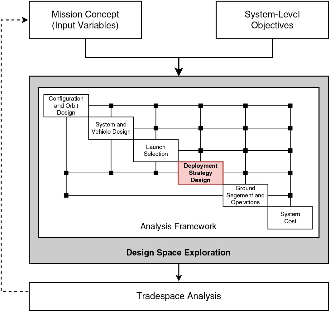
Figure 1. Methodology outline for the design-space exploration of small satellite constellation deployment. The central analysis framework features the integrated analysis method for the deployment of these systems.
In order to perform the integration of a method of deployment strategy analysis, a design framework approach is employed to organise the different contributing analyses to the design process and provide a structure by which information and the interdependent design variables can be exchanged between the different analyses. The scope of these contributing analyses can extend to the full mission life-cycle of the system to be designed, as demonstrated by the representative set of analyses for a small satellite constellation, presented in Fig. 1 in the form of a representative design structure matrix (DSM).
To develop such an analysis framework, a definition of the system and mission concept and the system-level objectives or metrics by which the different solutions can be assessed and compared are initially required. The set of contributing analyses needed to evaluate these output objective functions can then be defined and subsequently organised and simplified using a process of functional decomposition. The aim of this process is to reduce the number of feedback loops and iterative operations between the analyses.
In addition to the example analysis modules given in Fig. 1, mission-specific analyses may be required to evaluate the system objectives of particular interest to the system design team and other stakeholders. For example, for an Earth observation constellation analysis of the revisit time (Reference Ulybyshev26, Reference Razoumny27) of the system during the deployment phase may be of interest to the customer. Similarly, for a communications system the variation in level of service during deployment could be investigated and used as an output metric (Reference De Weck, De Neufville and Chaize28). However, if systems of significantly different type or application are to be considered together a means of system comparison and optimised decision-making process is required. Either simple common output metrics are therefore necessary or the concepts of an overall system utility or value can be considered to enable system selection (Reference Collopy and Hollingsworth29, Reference Vengadasalam, Desai, Hollingsworth and Smith30).
Design-space and tradespace exploration is used in the early design phases of complex engineering systems to enhance understanding of the design problem and support the identification of feasible, effective, or efficient solutions under the conditions of any system requirements and constraints. In addition, the process of design-space exploration can be used to increase the knowledge available to the design team about the interaction or tradeoffs between the input design variables and the output system characteristics. For the problem of small satellite constellation design, the variables comprising the input design-space can be nominally characterised as mixed discrete-continuous, due to the presence of both categorical, binary, and real-numbered variables. The number of variables and their range of possible values may be considerable, resulting in a very large design-space which requires exploration at significant computational cost. Furthermore, in the absence of a priori preference information, the multiple conflicting output objectives cannot be simply combined to form a single evaluation criterion. Finally, due to the nature of the contributing analyses, output objective gradients are not readily available and would have to be calculated using finite-differencing methods, increasing function calls significantly and therefore computational expense.
An a posteriori optimisation method is therefore chosen for this problem, primarily due to their capability to handle multiple objectives without an explicit preference structure and compatibility with the different variables present. A population-based approach was selected for the ability to search a large design-space for a set of Pareto-optimal solutions. Suitable methods of a posteriori optimisation include evolutionary and genetic algorithms, Pareto simulated annealing, and particle swarm optimisation. In this paper a multiobjective genetic algorithm, NSGA-II (Reference Deb, Pratap, Agarwal and Meyarivan31), is used to perform the design-space exploration. Whilst these methods are not certain to find the absolute Pareto-set of solutions or true global optimum, their operation can enable exploration of the significant design-space and supports the identification of promising system architectures and designs for further detailed development.
3.0 EXAMPLE FRAMEWORK DEVELOPMENT
Due to the complexity of the complete design process of a small satellite constellation, demonstration of the methodology is performed using a reduced-order analysis framework, focusing on the deployment of constellations of small satellites. In this implementation, shown in Fig. 2, the contributing analyses are limited to the constellation deployment simulation, preliminary vehicle and propulsion system sizing, and a model for estimating the cost of the system. These analyses were chosen to demonstrate the primary tradeoffs associated with the deployment of a small satellite constellation whilst remaining independent of the mission to be performed by the constellation.

Figure 2. Overview of the problem formulation to demonstrate the developed methodology. The structure of the reduced-order analysis framework is shown, focusing the design-space exploration on the system-level effects of constellation deployment design.
In order to inform the system design analysis, the chosen orbital design and configuration of the constellation are first needed. In addition, the launch or insertion Epoch of the payloads are required to evaluate the atmospheric environment. Finally, a representative mass of the spacecraft payload or system-bus is required as a starting point for the vehicle sizing procedure. For the deployment of constellations of small satellites by the method of indirect plane separation, the key design variables are the insertion orbit properties, propulsion system characteristics, and physical vehicle specification. In addition, if carrier vehicles are to be used in the deployment procedure, the propulsion system and physical properties of these vehicles are design variables used on the condition of a binary operator. The input information, design variables and output objectives for this design problem are summarised in Table 1.
Table 1 List of design variables, input parameters, output objectives and intermediary variables used in analysis framework and design-space exploration
3.1 Constellation deployment
Due to the typical regime of constellations of small satellites in low Earth orbit (LEO) and constrained nature of the propulsion systems used by these spacecraft, an analysis method for deployment which can accommodate the effects of orbital drag is required, increasing the complexity and computational cost of obtaining this information.
An analytical method describing the deployment of a constellation by the method of indirect plane separation is described by McGrath and Macdonald(Reference Mcgrath and Macdonald32). This method enables a rapid first order analysis of the necessary in-plane manoeuvres to achieve a given separation in right ascension of the ascending node (RAAN) and the tradeoff between ΔV and time to complete the deployment procedure. However, due to the analytical nature of the method , decay of the orbit is not considered during the manoeuvre and nodal drift periods. Due to the relationship between rate of drift in RAAN with orbital altitude, the returned solution may therefore be inaccurate for systems in LEO. Furthermore, for spacecraft with low-thrust propulsion systems or requiring large planar separations, this method may significantly underestimate the deployment time and ΔV and therefore the required propellant mass.
A method for analysis of satellite constellation deployment by indirect plane separation was previously presented by the authors in Crisp et al.(Reference Crisp, Smith and Hollingsworth33). This method utilises a semi-analytical orbit propagation technique and incorporates the NRLMSISE-00 atmospheric model and historical or forecast F 10.7 solar flux and A p geomagnetic index, enabling consideration of the decay of the satellites due to atmospheric drag during the manoeuvre and nodal drift periods. Analysis of deployment is performed using a simulation procedure which models the necessary orbit transfers and drift periods to achieve the correct mission configuration. Verification of this simulation method was performed by comparison to the actual deployment of the FORMOSAT-3/COSMIC mission (Reference Crisp25, Reference Crisp, Smith and Hollingsworth33).
The implemented deployment simulation and orbit propagation methods require input of the cross-sectional area, wet-mass, and coefficient of drag of the vehicles to enable calculation of the ballistic coefficient used in the evaluation of drag effects. Propulsion system characteristics and available propellant mass are also required to model the orbit transfer manoeuvres and ensure that the constellation can be successfully deployed. These parameters are provided by the vehicle and propulsion system design module.
3.2 Vehicle and propulsion system design
The selection and design of a propulsion system is a key factor in the design of a satellite constellation which requires deployment following launch. Exploration of the design-space and tradespace can be used to consider propulsion systems of different types, propellant, and sizes. Understanding of the tradeoffs associated with the different available design choices and identification of the most promising architectures can therefore be supported.
However, during the early design phases of a constellation mission different designs of the spacecraft may not have yet been approached or may have only been preliminarily outlined. In the absence of a detailed spacecraft design module the parameters required to perform the analysis of constellation deployment can be set using estimated or representative values from system models or sizing processes.
3.2.1 Propulsion system characterisation
A method of defining the major characteristics of different propulsion systems is required to provide information needed to perform the preliminary sizing of a spacecraft. Using a database of known propulsion systems for small satellites (less than 10 N), trends or relationships which exist between the characteristics of the different system types can be identified (Reference Crisp25, Reference Chiasson and Lozano34). These relationships can be used to predict the major characteristics of propulsion systems which are not contained in the database.
Three inputs are therefore needed to generate a characteristic propulsion system: system type, propellant type, and thrust magnitude. For the design-space exploration a thrust scalar is used rather than an absolute magnitude to allow for the significant variation in thrust capability between different propulsion system types. Values for the specific impulse, feed pressure, power requirement, and thruster mass are given as outputs. Depending on the propulsion system and propellant type, the molar mass, density, specific volume of vapour at saturation, and vapour pressure of the propellant and pressurant are also provided to support tank sizing.
3.2.2 Spacecraft mass
During the early design phases the dry-mass of the spacecraft can be estimated given the mass of the payload by rule-of-thumb or using data from existing and historical mission sets. For example Wertz(Reference Wertz, Wertz and Larson35) suggest a ratio of dry-mass to payload in the empirically determined range of 2:1 and 7:1.
Given a calculated value of the dry-mass of the spacecraft, mass budgets for the subsystem can subsequently be allocated in a top-down fashion. For more detailed analyses an iterative process may be required to perform trades between the different subsystems and update the top-level mass allocation in order to generate an acceptable system design. However, for this study only the fraction of the system allocated to the propulsion system is of interest. A maximum propulsion system dry-mass fraction, including tank mass and representative power system mass, is therefore implemented to ensure sufficient mass for the remaining subsystems.
The propellant mass mp needed to perform the necessary orbital manoeuvres is first calculated from the dry-mass of the spacecraft m 1, specific impulse Isp, and required ΔV (with an associated margin for losses due to finite burn durations) using the modified rocket equation, Equation (1)).
 $$\matrix{ {m_p = [e^{\Delta V/I_{spg0} } - 1]} } $$
The remaining dry mass of the propulsion system is determined by summation of the thruster mass obtained from the propulsion system model, the calculated mass of the propellant /pressurant tanks, and a representative mass of the power system required to operate the propulsion system.
The mass of the propellant and pressurant tanks can be calculated by assuming spherical tanks, nominal material density ρ tank and yield strength σ yield values, and a safety factor  $\overline {{\rm{SF}}} $. Using the volume V p and maximum pressure P max matching the form in equation 3b of the fluid to be contained, the mass of the tank m tank can be obtained by Equation (2).
 $$\matrix{ {m_{{\rm{tank}}} = {4 \over 3}\pi [(r_{{\rm{tank}}} + t_{{\rm{wall}}} )^3 - r_{{\rm{tank}}}^3 ]\rho _{{\rm{tank}}} } } $$
where the tank radius r tank and wall-thickness t wall can be calculated:
 $${{r}_{\text{tank}}}=3\sqrt{\frac{{{V}_{p}}}{\frac{4}{3}\pi }}$$
 $$\matrix{ {t_{{\rm{wall}}} = \overline {{\rm{SF}}} {{P_{\max } r_{{\rm{tank}}} } \over {2\sigma _{{\rm{yield}}} }}} } $$
The wet mass can finally be be determined by adding the calculated mass of propellant and pressurant to the dry mass of the spacecraft. Propulsion system mass margins are implemented to account for any additional components, pipework, control electronics, and uncertainty in the calculated propellant requirement.
Power system mass can be calculated by multiplying the required power of the propulsion system by a representative power density value, for example based on existing solar array or power-storage hardware.
3.2.3 Cross-sectional area
Given the total mass of a satellite the volume and cross-sectional area can be estimated using trends fitted to the available data of historical missions. A relationship was identified by Wertz(Reference Wertz, Wertz and Larson35) for satellites launched between 1978 and 1984 with mass in the range 35 kg to 3625 kg. However, new relationships are required for modern small satellites, particularly in the smaller nanosatellite and picosatellite classes. A new fitted relationship, based on satellites launched between 1990 and 2015, has therefore been identified for these small satellites (<1000 kg), utilising the guidance of Oltrogge and Leveque(Reference Oltrogge and Leveque36) and is indicated in Fig. 3, showing clear divergence with the Space Mission Analysis and Design trend for spacecraft of smaller mass.
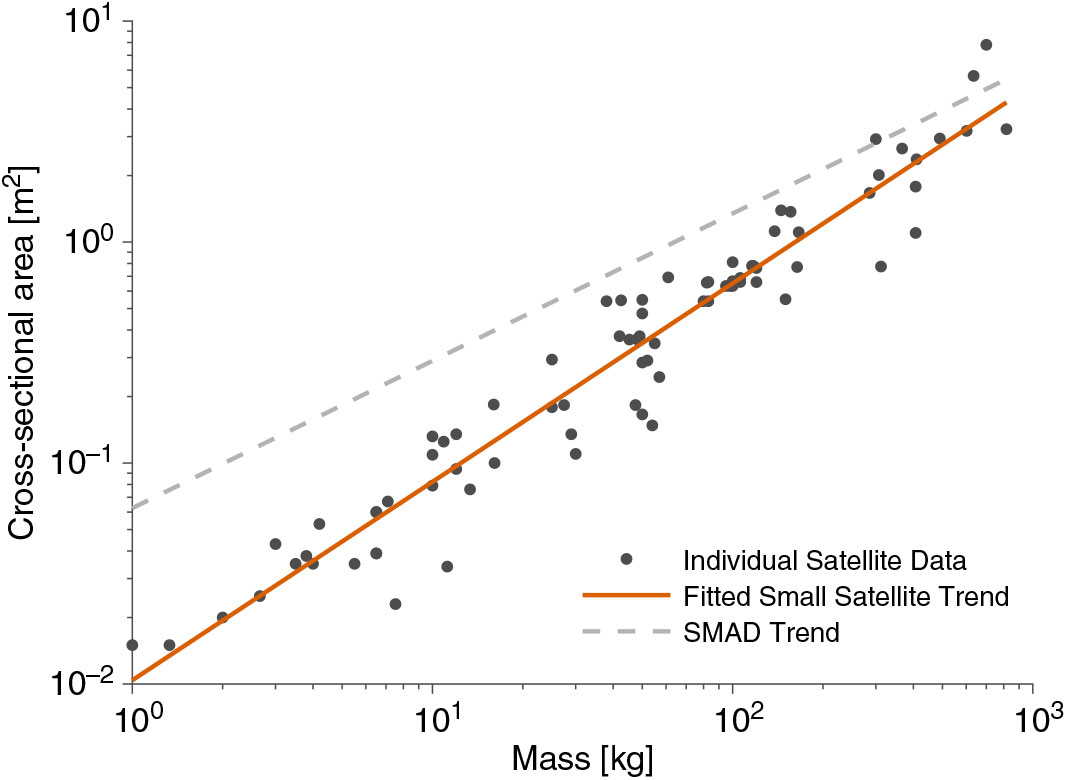
Figure 3. Relationship between mass and cross-sectional area of small satellites.
3.3 Cost modelling
Knowledge of the cost or potential benefit of different design architectures identified during the design-space exploration process can be used by the system design team to understand the tradeoffs between system cost and deployment strategy design and enable business-based decisions.
Parametric cost models based on cost-estimating relationships (CERs) derived from historical information of satellite missions are frequently used to provide a relative measure of the cost of different system designs. Alternatively, value-centric/driven design or economic benefit analyses based on business modelling methodologies can be used to evaluate the different designs and aid selection. For example, value-based analyses have been performed for fractionated space systems including the F6 project (Reference Mccormick, Barrett and Burnside-Clapp37, Reference Eichenberg-Bicknell, Wisniewski, Choi and Westley38), whilst Golkar and Lluch I Cruz(Reference Golkar and Lluch I Cruz39) present an economic assessment of a commercial communications business utilising federated satellite systems. However, the development of such a method applicable to different mission applications is beyond the scope of this study and simple parametric cost models will be used to demonstrate this capability.
A number of different parametric cost models for space systems are publicly available. However, many of these models are based on traditional large satellites and are therefore not appropriate for small satellite cost estimation. The Small Satellite Cost Model (SSCM) of The Aerospace Corporation (Reference Lao, Mosher and Neff40) is therefore implemented in this study. For larger carrier vehicle spacecraft, where the cost-estimating relationships of the SSCM are no-longer valid, the USAF Unmanned Space Vehicle Cost Model (USCM) is used (Reference Wertz, Wertz and Larson35).
In the absence of complete system design information, three appropriate CERs are identified. In Equations (4a) and (4b), derived from the SSCM, the system costs Yi are proportional to the spacecraft dry-mass X 1 and dry propulsion system mass X 2 respectively. In Equation (4c), from the USCM, the system cost Y 3 is related to spacecraft dry-mass X 1.
 $$\matrix{{Y_1 \alpha X_1^{0.661} } & {{\rm{for}}X_{\rm{1}} \le 400{\rm{kg}}} } $$
 $$\matrix{{Y_2 \alpha 1.0096^{X_2 } } & {{\rm{for}}X_2 \le 35{\rm{kg}}} } $$
 $$\matrix{{Y_3 \alpha {{43} \over {1000}}X_1 } & {{\rm{for}}X_{\rm{1}} \ge 400{\rm{kg}}} } $$
In order to provide compatibility between Equations (4a) and (4c), a correction is applied which creates a continuous interface at the crossover point of 400 kg spacecraft dry-mass. Similarly, the propulsion system mass dependent CER Y 2 is scaled to the magnitude of Y 1 to enable averaging of the different CERs to provide a single cost metric. This resulting cost estimate is therefore unitless and can only be considered a relative measure for comparison of different designs as proportional relationships are considered and correction factors have been applied.
3.4 Design-space exploration
In order to explore the design space, a single or set of objective functions is required which direct the optimisation or exploration process. However, for the problem of satellite constellation deployment the output objectives cannot be easily combined without a priori customer/stakeholder preference information and mission-specific analyses. A meaningful overall objective criteria, for example value or utility, cannot therefore be formulated without this additional information. However, a multiobjective approach can be used to facilitate the exploration and understanding of the design-space through identification of system-level tradeoffs and Pareto-efficient solutions rather than seeking a single optimum solution.
The NSGA-II algorithm (nondominated sorting genetic algorithm II (Reference Deb, Pratap, Agarwal and Meyarivan31)) was selected and implemented using the MATLAB gamultiobj routine. The NSGA-II algorithm was chosen for its elite-preserving characteristic which protects the most successful individual solutions between each generation. Its implementation in MATLAB is also compatible with parallel processing and can therefore increase the computational efficiency and reduce the time required to effectively explore the design space.
The input parameters required for the example framework are given in Table 1. Additional input parameters required to perform a given analysis or case-study are also provided. Selection, recombination, and random variation of the best performing individuals in successive populations is also implemented through tournament selection, adaptive mutation, and two-point crossover functions. The selection of population size and number of executed generations (or stopping-criteria) is also a balance between the computational expense, solution convergence, and solution diversity. A more complete description of the NSGA-II implementation is given by Crisp(Reference Crisp25).
The output objectives of the analysis framework for constellation deployment are given in Table 1. The total system mass is defined as the sum of the mass of all vehicles associated with a single design point at the time of orbital insertion, and therefore includes the propellant mass. The time to deploy of the constellation is defined as the duration from orbital insertion to completion of the intended constellation configuration. The total system cost is defined using the CERs defined in Section 3.3 and is the sum of the per-unit build cost of the vehicles associated with a given design point.
4.0 MISSION CASE-STUDIES
Using the described analysis framework, a series of three constellations of small satellites are investigated to demonstrate the value of considering the deployment of these systems during the design process and the benefits which can be realised with increased understanding of the tradeoffs and relationships in the system design-space. The first two examples presented are based on satellite constellations which have already been established in orbit, enabling comparison to true system performance. A proposed system of nanosatellites for Earth observation, with similarity to the Planet Labs Flock constellation, is examined in the third case-study.
4.1 Case study I: FORMOSAT-3/COSMIC
The FORMOSAT-3/COSMIC mission is a GPS-RO constellation of six microsatellites arranged in a modified Walker Delta configuration of six equispaced orbital planes about 180° in RAAN (Reference Fong, Shiau, Lin, Kuo, Chu, Yang, Yen, Chen, Kuo, Liou and Chi13). The satellites are also phased with respect to each other in their orbits to maximise the downlink of mission data. The constellation was launched in April 2006 and deployed over a period 20 months using the method of indirect plane separation. To perform this deployment, each satellite was equipped with an individual blowdown monopropellant Hydrazine propulsion system with gaseous Helium pressurant.
A point-design of the FORMOSAT-3/COSMIC mission can be used to compare the designs identified during the design-space exploration process to the true mission. The actual point-design can be defined using available data from post-mission analysis presented by Fong et al.(Reference Fong, Shiau, Lin, Kuo, Chu, Yang, Yen, Chen, Kuo, Liou and Chi13). However, due to a number of operational issues and hardware failures which affected the deployment phase during the actual mission this point-design may not fairly represent the system design. A simulated point-design can therefore be defined which assumes nominal mission performance and does not account for the significant propellant margin of 45% which was implemented on the mission. In both cases, due to lack of available project cost information, the comparative cost metric is generated using the previously defined CERs.
4.1.1 Problem definition
The input parameters and design variable bounds for the FORMOSAT-3/COSMIC mission are provided in Tables 2 and 3. The input parameters were selected to most closely resemble the true deployment of the constellation, whilst the deployment deadline parameter was chosen to limit the maximum length of each analysis whilst ensuring that deployment strategies which are longer than the true mission can be considered.
Table 2 FORMOSAT-3/COSMIC design-space exploration input parameters (Reference Fong, Shiau, Lin, Kuo, Chu, Yang, Yen, Chen, Kuo, Liou and Chi13)
Table 3 Design variable bounds for design-space exploration of FORMOSAT-3/COSMIC mission
4.1.2 Tradespace analysis
The most promising of the overall set of designs can be selected by considering the Pareto-optimality or dominance of each solution. In a multiobjective space, a solution can be considered nondominated if its value in any one objective cannot be improved on by another known solution without reducing the value in one or more of the other objective criteria. The set of nondominated designs and solutions for the FORMOSAT-3/COSMIC mission design-space exploration are shown in Fig. 4.
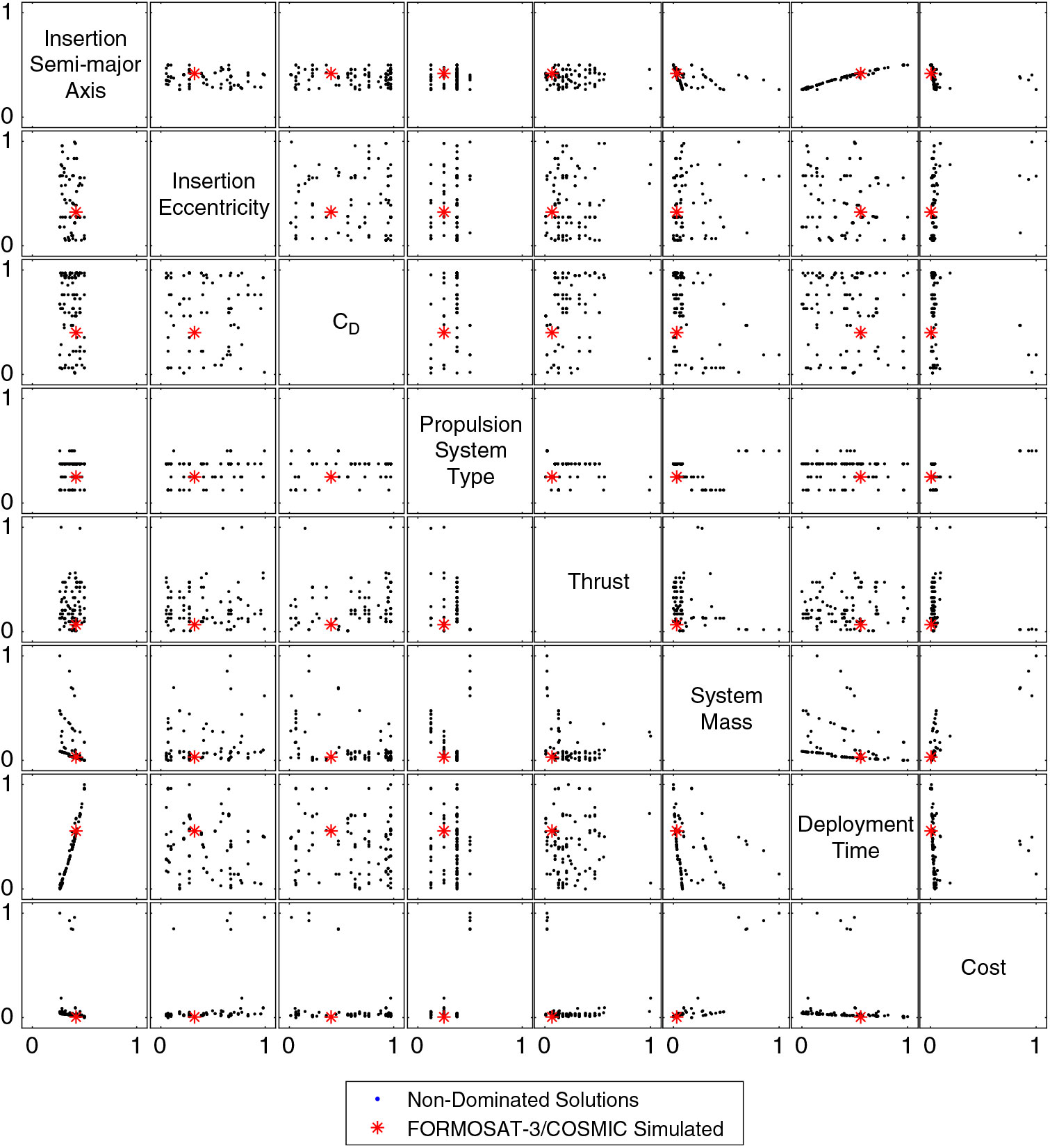
Figure 4. Scatter-plot matrix of input and output variables of nondominated solution set for FORMOSAT-3/COSMIC mission analysis.
This scatter plot matrix demonstrates the spread of solutions in the design-space, and the relationship between some of the design variables and output objective parameters. For example, a clear band of feasibility is shown for the insertion semi-major axis (0.25 to 0.5 in the normalised range, corresponding to 6775 km to 6950 km ). The upper limit of feasibility is established by the requirement to perform the deployment within a prescribed time period, imposing a minimum bound on the rate at which plane separation must occur. The presence of atmospheric drag imposes the lower limit on feasibility, as orbital decay and deorbit may occur before the deployment can be performed. Different propulsion system types are shown as strata corresponding to, in ascending order, cold-gas thruster (CGT), monopropellant, bipropellant, resistojet, arcjet, ion, and high- and low-power hall-effect. The spread of designs for different propulsion system type variable indicates that few feasible solutions exist for the more energetic propulsion systems.
The output space of nondominated designs catagorised by propulsion system type are also shown in Fig. 5 with comparison to the mission point-designs. These results indicate that the fastest deployment of the constellation can be achieved using either CGT, monopropellant, or bipropellant propulsion systems. This is attributable to their relatively high thrust capability which enables a greater orbit separation, reducing the necessary nodal drift-time. Conversely, the designs with lowest total system mass are achieved using arcjet and low-power Hall-effect thruster systems which can achieve greater specific impulse. However, for minimum relative cost, the lower specific impulse systems are dominant due to the dependence of the CERs on spacecraft dry-mass and dry propulsion system mass.
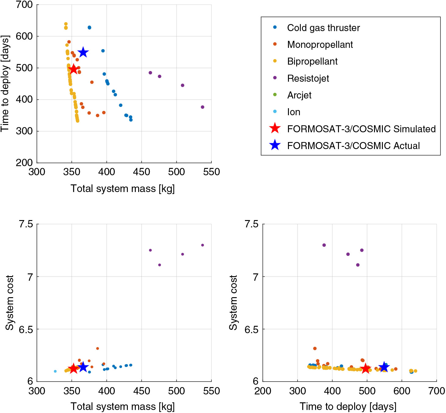
Figure 5. Output space of nondominated solution set obtained for FORMOSAT-3/COSMIC mission analysis. Plots are normalised with respect to their upper and lower bounds for input variables and with respect to their total range for output objectives.
In this solution set it is shown that bipropellant systems are generally dominant over monopropellant systems which are poorly represented in the nondominated space, primarily due to their reduced specific impulse. However, despite an increased performance capability, bipropellant systems can have a significant complexity penalty and are subject to greater safety considerations due to handling and storage of hypergolic propellants or powerful oxidising agents, factors which are not accounted for by the implemented analysis framework. This demonstrates a necessity for either an all-encompassing analysis framework or the expression of preferences by the system design team in order to identify and select the most appropriate design.
In the actual FORMOSAT-3/COSMIC mission design, Hydrazine monopropellant propulsion systems were used. Compared to the solutions identified by the design-space exploration process the actual result is clearly dominated, attributable to the increased deployment time due to issues with the mission operations and additional propellant mass carried by the actual FORMOSAT-3/COSMIC spacecraft. The simulated result expectedly falls in line with the monopropellant systems due to the use of the analysis framework to generate the output parameters. However, the design is not nondominated or Pareto efficient, suggesting that at least one of the output objectives could have been improved by considering a different propulsion system or propellant choice.
Most significantly, the design-space exploration process indicates that the deployment time of the constellation could have been significantly reduced (by up to 50%) for only a small increase in total system mass (less than 1 kg per satellite), reducing the time to full scientific operations and increasing the overall scientific return of the mission.
4.2 Case study II: The ORBCOMM constellation
The first generation ORBCOMM system is a LEO satellite constellation launched between 1995 and 1999 with the aim to provide global wireless data transfer and messaging services. The core component of the system is a 32-satellite Walker Delta constellation of 4 equispaced planes.
The ORBCOMM constellation was established using one launch to each specified orbital plane. To complete the deployment of the constellation only insertion correction and phasing of the satellites within each orbital plane was therefore required, performed using an individual Nitrogen CGT propulsion system on each satellite.
The launch of the core Walker Delta configuration of the constellation was completed over a period 721 days. The mass of each of the satellites launched was 45 kg (Reference Patel, Schroll and Lewin41), resulting in a total mass of 1440 kg. However, a complete point-design vector for the true ORBCOMM constellation launch cannot be determined as cost of the satellites is not reported in the literature. However, the system deployment and total mass can be compared to the results of the design-space exploration nonetheless.
4.2.1 Problem definition
The input parameters and design variable bounds for the ORBCOMM constellation are provided in Tables 4 and 5. Due to the requirement of multiple satellites in each orbital plane, carrier vehicles are considered in this analysis and thus the additional design variable of separation spring velocity is necessary. The insertion date was chosen to coincide with the first launch of the actual ORBCOMM satellites. Representative space weather conditions, obtained from historical archives, can therefore be used during the deployment analysis.
Table 4 ORBCOMM design-space exploration input parameters
Table 5 Design variable bounds for design-space exploration of ORBCOMM mission
4.2.2 Tradespace analysis
The total solution set is shown in Fig. 6, featuring both designs which use only individual satellites and strategies which utilise carrier vehicles. In this output space, a mass penalty is indicated for designs which utilise carrier vehicle against self-deploying satellites, with the exception of individual satellites with the lowest specific impulse CGT propulsion systems. However, due to their greater thrust capability, designs utilising carrier vehicles are shown to be capable of achieving the shortest deployment time of all identified solutions. With respect to the relative cost metric, the designs featuring carrier vehicles are observed to be more costly than individual satellite deployment architectures. However, due to the simplicity of the CERs, the implemented cost model may not wholly capture the benefits of carrier vehicle designs, for example, reductions in design and manufacturing complexity or constraints.
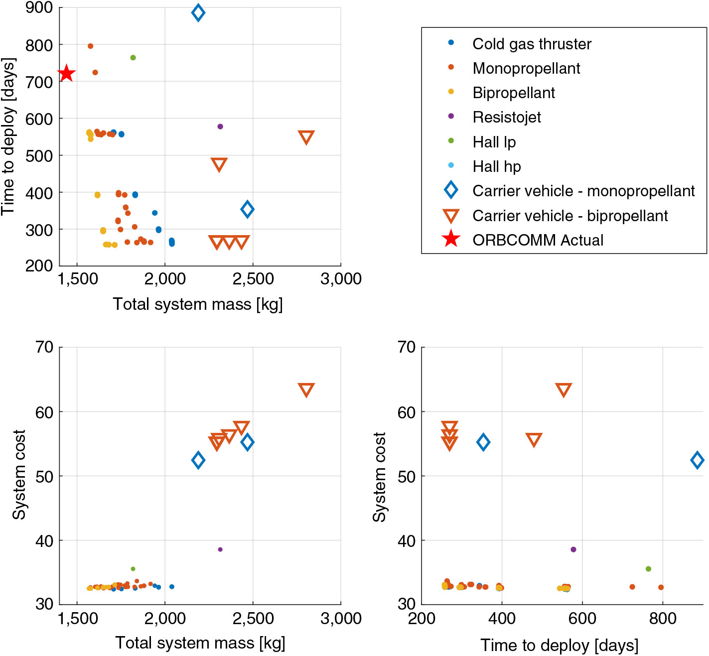
Figure 6. Output space of total solution set obtained for ORBCOMM mission analysis. The ORBCOMM Actual point-design is not featured in cost plots due to incompatibility of cost information.
As the deployment of the actual ORBCOMM constellation was performed using multiple launch vehicles, each delivering the satellites to their mission orbital plane, no solutions identified by the design-space exploration process are able to achieve a lower total system mass. However, many solutions demonstrate a shorter time to deploy than the actual ORBCOMM mission. Constellation deployment times as short as 257 days are identified, which would have allowed commercial operations to commence sooner.
Furthermore, the cost of deployment by the method of indirect plane separation, requiring a single launch, may be significantly different compared to the cost of the actual ORBCOMM system. Using the nominal cost of the Pegasus-XL HAPS launch vehicle reported by Isakowitz et al.(Reference Isakowitz, Hopkins and Hopkins42), the total cost of the 4-plane deployment would have been $100M. However, launch of the complete system on a single vehicle, assuming a total system mass of less than 2000 kg, could be achieved for about $45M using a Delta-II launch vehicle (Reference Isakowitz, Hopkins and Hopkins42). This represents a saving of 55% on launch costs alone, corresponding to approximately 17% of the reported total system cost of $330M (Reference Barnhart, Vladimirova and Sweeting43, Reference Hardy44). However, this comparison does not take into account other economic or operational aspects of the launch strategy decision making process, for example, rate of satellite manufacture, phased constellation set-up, or risk analysis.
4.3 Case study III: Earth Observation nanosatellite system
In this third case study, an Earth Observation (EO) constellation of nanosatellites is considered. A proposal made by Andrews(Reference Andrews45) consists of 80 nanosatellites in a low-ball configuration, a Walker Delta pattern with 8 planes at 55° inclination, and a further two high-ball planes in a sun-synchronous orbit of 10 satellites each. The proposed satellites are of 6U CubeSat form factor, for which an initial mass of 6 kg is defined, reserved for the payload and satellite bus before the addition of a propulsion system.
This style of constellation has similarities to the Planet (formerly Planet Labs) Flock constellation which consists of satellites in both SSO and multiple inclined LEO, providing a reported daily revisit capability (Reference Boshuizen, Mason, Klupar and Spanhake46). However, this constellation has been built-up over a period of several years, beginning in 2014, making use of multiple secondary payload launch opportunities and deployment from the ISS to achieve the current planar configuration.
In this example, the simultaneous launch of the low-ball planes using a secondary-payload opportunity and subsequent deployment to the mission configuration is considered. Carrier vehicles deployment strategies are also considered, allowing the satellites for each plane of the constellation to utilise a common propulsion system to perform the required inclination and nodal-drift manoeuvres.
4.3.1 Problem definition
The input parameters and design variable bounds for this nanosatellite constellation are provided in Table 6 and 7. An on-orbit lifetime of the proposed spacecraft of 36months is specified by Andrews(Reference Andrews45). A deployment period of 2 years was therefore selected such that any identified designs would result in at least a complete year of full mission capability following the completion of deployment before the design lifetime of the satellites is exceeded.
Table 6 EO nanosatellite constellation design-space exploration input parameters
Table 7 Design variable bounds for design-space exploration of EO nanosatellite constellation
This analysis explores deployment following a secondary payload launch opportunity based on a scheduled launch of a SpaceX Commercial Resupply Services mission to the ISS in May 2019. A change of inclination, distribution of the constellation planes, and in-plane phasing manoeuvres are therefore required to complete the deployment of the constellation.
4.3.2 Tradespace analysis
The nondominated solution set for each propulsion system type is shown in Fig. 7, demonstrating a significant range of different deployment architectures and propulsion system choices which result in feasible solutions. For this constellation of nanosatellites, the mass and cost of carrier vehicle use is shown to be more competitive with individual satellite architectures. Many of the carrier vehicle solutions are of similar or smaller total system mass to the individual satellite designs and and could therefore be delivered to orbit using the same launch opportunities. This is attributable to the required inclination change manoeuvre and and the benefits in propulsion system scaling that a carrier vehicle can potentially provide.
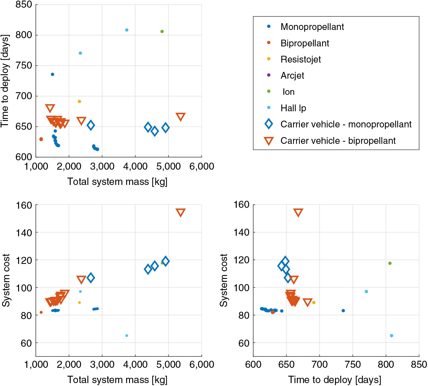
Figure 7. Output space of nondominated solution set obtained for EO nanosatellite mission analysis.
However, in the output space the designs of shortest deployment time remain individual satellites, principally with monopropellant propulsion systems. This is due to the performance range of the propulsion system in the available database (<10 N), which restricts the thrust-to-mass ratio of the carrier vehicles and therefore their deployment capability.
Interrogation of the system mass of the output solutions, shown in Fig. 8, demonstrates that the individual satellites suffer from a significant increase in mass, principally attributed to the requirement of a propulsion system. Subsatellites associated with a carrier vehicle are able to generally remain within their design form factor (6U CubeSat, <12 kg), whilst the carrier vehicles, particularly those with bipropellant systems, are also able to maintain a reasonable propulsion system mass fraction.
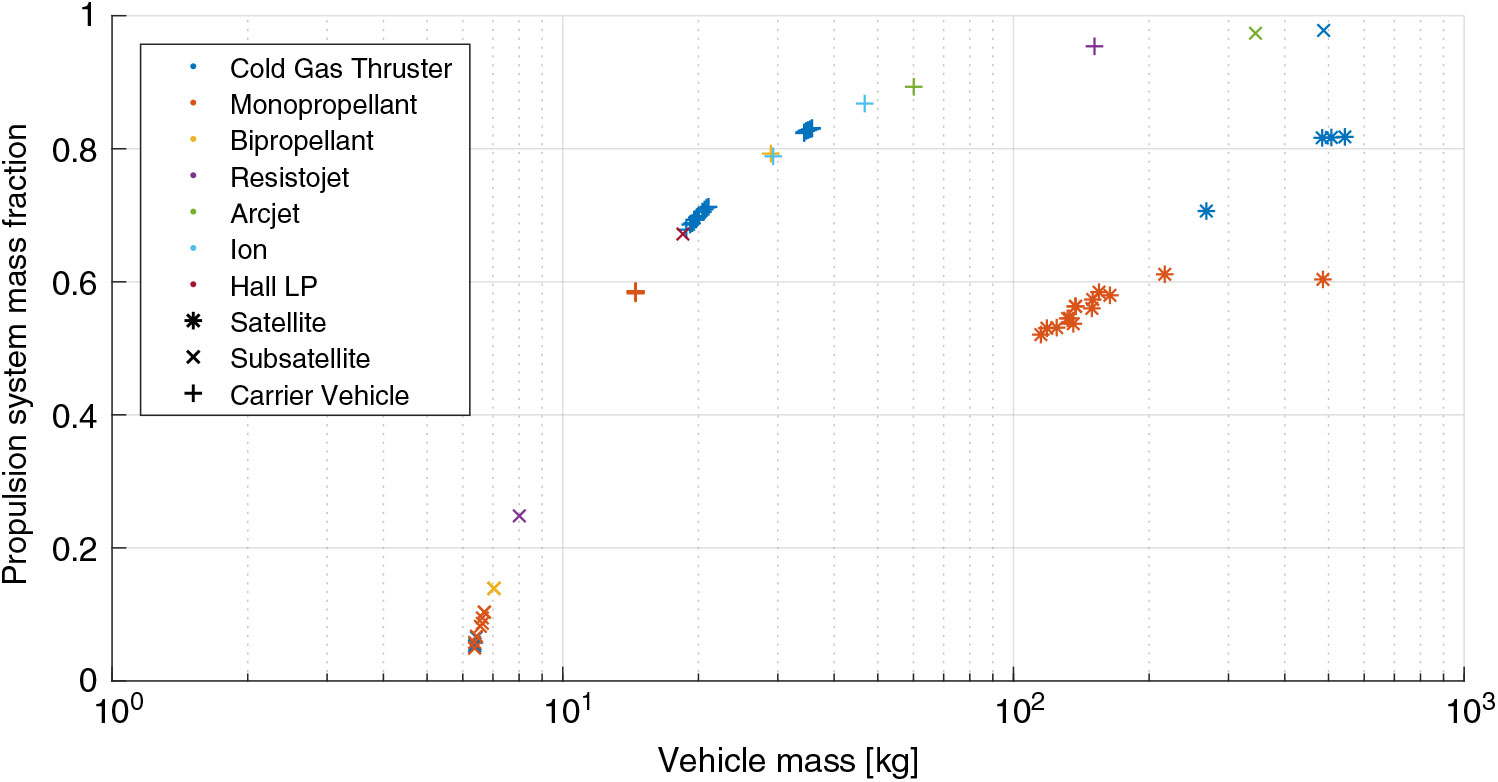
Figure 8. Vehicle mass and associated propulsion system mass fraction for EO nanosatellite mission analysis. (Marker type indicates vehicle type and colour represents propulsion system type.)
5.0 CONCLUSIONS
The methodology presented in this paper enables the consideration of the deployment of constellations of small satellites during the wider design process through the use of an integrated analysis framework approach. By utilising design-space exploration, the different strategies for deployment can be investigated and their effect on the output system design better understood. Furthermore, by examination of the output tradespace resulting from an optimisation process, the best performing system architectures can be identified and selected for further detailed design and development. The information provided by the design-space exploration process enables more informed decision making and further supports the development of improved overall system and mission designs which may result in reduced system cost or improvements in capability or revenue generation.
In the presented case-studies, examined using a reduced-order analysis framework, improvements to existing constellations were identified resulting in either reduced overall system mass or a shorter deployment time. For the FORMOSAT-3/COSMIC mission it was shown that deployment period could have been reduced by 50% whilst incurring only a small penalty in mass. Significant cost-savings on the order of $55M were also identified for the ORBCOMM constellation through launch by a single vehicle and deployment using the method of indirect plane separation. The time to deploy this constellation and therefore time to full operational status could also be significantly reduced using this deployment method, with potential benefits to revenue generation.
The deployment of a large Earth Observation nanosatellite constellation was also considered, utilising a secondary payload launch strategy. The design-space exploration indicates that a range of different deployment strategies and propulsion system types result in feasible and interesting solutions which could be taken forward for further development and analysis. However, these results are subject to the available propulsion system models, currently based on a database of existing systems and heuristically fitted trends, and cost-models which can be reasonably applied during the early design phases.
Further development of this work will seek to apply this methodology with extended and mission-specific analysis frameworks to explore the greater design-space for future space systems. In particular, implementation of analyses for the constellation configuration and orbit design, launch opportunity selection, and ground-segment or mission operations would support a more complete consideration for the total life-cycle design of satellite constellations. Likewise, analysis of a greater range of constellation deployment strategies, including direct-transfers and differential drag separation schemes, would increase the available design-space for exploration. In cooperation with these extended and additional analysis modules, further development of the spacecraft preliminary design module and system cost model are also required to support a deeper understanding of the system tradespace and to improve the credibility of the output system metrics and performance for industrial and commercial application.
ACKNOWLEDGEMENTS
The authors would like to thank Dr Peter C E Roberts and Dr Malcolm Macdonald for their valuable help and suggestions in improving this work. This work was supported by the Doctoral Training Partnership (DTP) between the University of Manchester and the UK Engineering and Physical Sciences Research Council (EPSRC) [EP/J50032X/1].


 Open access