


Impact Statement
Among a variety of unsteady flow problems affecting flying-wing aircraft, wing rock has been receiving widespread attention as it can seriously affect the manoeuvrability, takeoff and landing performance and weapon delivery performance of an aircraft, restrict the flight envelope and even endanger flight safety. The present study finds that the flying wing has a wing rock mode different from that of other aircraft such as the slender delta wing, non-slender delta wing, rectangular wing and generic aircraft configuration, which can be attributed to its unique flow structures, i.e. the ‘vortex–shear-layer’ system. The present findings reflect the important influence of aerodynamic shape on the stability of flying-wing aircraft and can provide a reference for the design of flying-wing configuration aircraft to improve flight performance and expand the flight envelope.
1. Introduction
The flying wing is an advantageous aerodynamic configuration, which has great application potential in modern aircraft design. Due to the blend of the wings and fuselage, its lift-to-drag ratio is significantly improved, thus resulting in higher aerodynamic efficiency (Reference Qu, Zhang, Shi and LyuQu, Zhang, Shi, & Lyu, 2017; Reference Roman, Alien and LiebeckRoman, Alien, & Liebeck, 2000) and structural efficiency (Reference LiebeckLiebeck, 2004; Reference Song, Yang, Yan, Ma and HuangSong, Yang, Yan, Ma, & Huang, 2015). Simultaneously, the radar cross-section is reduced, leading to good stealth performance (Reference Li, Bai, Li, Meng, Liu and ChenLi et al., 2019). These advantages make the flying-wing aircraft appropriate for both military and civil applications. However, because the flying wing has no vertical and horizontal tails, as well as some traditional control surfaces, the lateral-directional stability and manoeuvrability have always been the main problems limiting its application (Reference Keidel, Fasel and ErmanniKeidel, Fasel, & Ermanni, 2020; Reference Larkin and CoatesLarkin & Coates, 2017).
There have been several representatives flying-wing aircraft in history, such as the Ho-229 fighter bomber, the B-2 bomber, the X-47B carrier-based aircraft, the Boeing BWB airliner, etc. These aircraft generally have a high aspect ratio and low manoeuvrability, and can only cruise at subsonic or high subsonic speed. In contrast, the low-aspect-ratio flying wing, which is more suitable for supersonic flight and high manoeuvrability, has rarely been used in practice before. This is because the problem of the lack of lateral-directional stability is more prominent for it. Moreover, for a low-aspect-ratio flying wing, due to its large sweep angle, three-dimensional vortical flow is introduced at high angles of attack, which affects the pitching moment (Reference Tomac and StenfeltTomac & Stenfelt, 2014) and thus complicates the flight control. For the longitudinal trim problem, if the wingtips functionally serve as a horizontal tail of the flying wing, it may impose a significant induced drag penalty. Therefore, a near-elliptic span load should be considered (Reference LiebeckLiebeck, 2004). However, in recent years, due to the strong demand for high-performance aircraft, increasingly more researchers have begun to pay attention to and try to solve the various flight control problems faced by low-aspect-ratio flying wings (Reference Harvey, Gamble, Bolander, Hunsaker, Joo and InmanHarvey et al., 2022; Reference Löchert, Huber, Ghoreyshi and AllenLöchert, Huber, Ghoreyshi, & Allen, 2019).
Among a variety of unsteady flow phenomena affecting high-manoeuvrability aircraft, wing rock has been receiving widespread attention. Wing rock is a kind of unsteady motion phenomenon of slender aircraft in the pre-stall stage at high angles of attack. The aircraft mainly oscillates periodically around its roll axis, coupled with motions along the other degrees of freedom, but the roll oscillation is dominant (Reference Nelson and PelletierNelson & Pelletier, 2003; Reference SchmidtSchmidt, 1979). Previous studies of wing rock mainly focused on three types of simplified models. The first type is the delta wing, including the slender delta wing (Reference Arena and NelsonArena & Nelson, 1992, Reference Arena and Nelson1994; Reference EricssonEricsson, 1984; Reference Ng, Malcolm and LewisNg, Malcolm, & Lewis, 1992) and the non-slender delta wing (Reference EricssonEricsson, 2001; Reference Gresham, Wang and GursulGresham, Wang, & Gursul, 2010b; Reference Matsuno and NakamuraMatsuno & Nakamura, 2000; Reference McClain, Wang, Vardaki and GursulMcClain, Wang, Vardaki, & Gursul, 2007). Reference EricssonEricsson (1995), Reference MabeyMabey (1997), Reference KatzKatz (1999), Reference Nelson and PelletierNelson and Pelletier (2003), Reference Gursul, Gordnier and VisbalGursul, Gordnier, and Visbal (2005) and Reference GursulGursul (2005) have comprehensively reviewed this topic. The second type is the low-aspect-ratio wing, including rectangular wings, elliptical wings and irregular plane wings. Its application background is mainly for micro air vehicles at low Reynolds numbers (Reference Go and MaqsoodGo & Maqsood, 2015; Reference Gresham, Wang and GursulGresham, Wang, & Gursul, 2010a; Reference Hu, Cheng, Liu, Huang and AkkermansHu, Cheng, Liu, Huang, & Akkermans, 2020; Reference Levin and KatzLevin & Katz, 1992; Reference Williams and NelsonWilliams & Nelson, 1997). The third type is the generic aircraft configuration (Reference Brandon and NguyenBrandon & Nguyen, 1988; Reference Ericsson, Mendenhall and PerkinsEricsson, Mendenhall, & Perkins, 1996; Reference Ma, Deng, Rong and WangMa, Deng, Rong, & Wang, 2015; Reference Ma, Wang and DengMa, Wang, & Deng, 2017; Reference Shi, Deng, Wang, Li and TianShi, Deng, Wang, Li, & Tian, 2015), and a pair of forebody leeward vortices is the main feature of its flow field. Besides the above simplified models, many actual aircraft have also been reported to exhibit the wing rock phenomenon in wind tunnel experiments or flight tests, such as the HP 115 (Reference RossRoss, 1972), F-4, F-5, F-14, Gnat, Harrier (Reference Hsu and LanHsu & Lan, 1985), X-29, X-31 (Reference Ericsson, Mendenhall and PerkinsEricsson et al., 1996), AV-8B (Reference Hall, Woodson and ChambersHall, Woodson, & Chambers, 2004), F/A-18E fighter (Reference Owens, Bryant and BarlowOwens, Bryant, & Barlow, 2006), F-35 fighter (Reference Owens, McConnell, Brandon and HallOwens, McConnell, Brandon, & Hall, 2006), a canard-configuration aircraft (Reference Wei, Shi, Geng and AngWei, Shi, Geng, & Ang, 2017) and a generic fighter aircraft with a conical forebody (Reference Chung, Cho, Kim and JangChung, Cho, Kim, & Jang, 2021).
For a low-aspect-ratio flying wing, the wing rock phenomenon also occurs in a particular parameter envelope because of its slenderness and leading-edge vortex (LEV)-dominated flow field. However, there are still great differences between the flying wing and the slender delta wing. First, the low-aspect-ratio flying wing usually has complex camber bulges on the windward and leeward surfaces, which can interfere with the LEVs. Second, the bulge shape on the leeward surface near the nose occupies the space initially belonging to the LEV so that the separated shear layer near the nose of the flying wing cannot roll up into an LEV. Third, the low-aspect-ratio flying wing should adopt high-subsonic or supersonic airfoils, while the leading-edge shape is an important factor affecting the wing rock phenomenon (Reference Miau, Kuo, Liu, Hsieh, Chou and LinMiau et al., 1995). Due to the unique aerodynamic shape of the flying wing, it is necessary to conduct specific research on its wing rock motion to understand its unique characteristics and deep-level driving mechanism. However, there are few studies of the wing rock motion of a specific flying-wing configuration, especially of the low-aspect-ratio flying wing. Moreover, the wing rock is a highly unsteady and three-dimensional flow situation. Although there have been many experimental studies of wing rock motion of various aircraft such as the delta wing, most of these studies are limited to non-time-resolved two-dimensional particle image velocimetry, and there are few reports of the evolution characteristics of the three-dimensional flow field. Furthermore, due to the limitation of calculation expense and model accuracy, the previous numerical simulation research on wing rock motion (Reference ArenaArena, 1992; Reference Badcock, Woodgate, Allan and BeranBadcock, Woodgate, Allan, & Beran, 2008; Reference Chaderjian and SchiffChaderjian & Schiff, 1996; Reference Konstadinopoulos, Mook and NayfehKonstadinopoulos, Mook, & Nayfeh, 1985; Reference Lee and BatinaLee & Batina, 1991; Reference Liu, Zhang and ZhaoLiu, Zhang, & Zhao, 2006; Reference Pamadi, Rao and VigyanPamadi, Rao, & Vigyan, 1994; Reference SaadSaad, 2000) mostly adopted an inviscid model or simplified viscous model, or without detailed time-dependent evolution of flow structures being exhibited, so it cannot fully reflect the evolution characteristics of the complex flow field.
This study applies a low-aspect-ratio flying wing model with a sweep angle of 65° to wind tunnel experiment and numerical simulation. The evolution of the three-dimensional flow structures of the flying wing in both the static case and dynamic motion is introduced. This study also compares the differences between the flying wing, the 65° delta wing and the 80° delta wing, and finds that the flying wing has a different wing rock mode, corresponding to a different energy exchange manner in the process of wing rock, which can be attributed to its unique flow structures and dynamic hysteresis characteristics. Thus, this study reveals the driving mechanism of a flying wing's wing rock and enriches the understanding of the classic problem of wing rock.
2. Methodology
2.1 Physical model
In this study, a low-aspect-ratio flying wing unmanned aerial vehicle model was used, as shown in figure 1(a–d). For the flying wing model, the backward sweep angle of the leading edge was 65°, the forward sweep angle of the trailing edge was 47°, the root chord length c = 0.306 m, the span length b = 0.229 m and the wing area S = 0.0338 m2. The moment reference point of the model coincided with the centre of gravity, which was in the symmetry plane of the fuselage, with an axial distance of 0.176 m and a normal distance of 0.008 m to the apex point. Smooth integration of the wings and fuselage was adopted by the model, whose longitudinal layout was the so-called stingray configuration (figure 1b). On the fuselage of the model, there were streamlined bulges on the back and abdomen (figure 1c,d), which extended from the nose to the vicinity of the trailing edge. In this study, as shown in figure 1(a,b), the definition of the body coordinate system is as follows: the origin was the nose apex of the model; the O–x axis was in the symmetry plane of the fuselage and points forward; the O–y axis was perpendicular to the symmetry plane and points to the right-hand side; and the O–z axis was also in the symmetry plane and points downward. Besides the flying wing model, two delta wings with sweep angles of 65° and 80° respectively were also studied for comparison, as shown in figure 1(e,f). Both the delta wings have the same root chord length c = 0.306 m as the flying wing model, and both have a thickness of 3 mm and a sharp leading edge of 20° (figure 1g), which is similar to the models used by Reference Gresham, Wang and GursulGresham et al. (2010b).

Figure 1. (a) Axonometric view, (b) top view, (c) front view and (d) side view of the flying wing; (e) top view of the 65° delta wing, (f) top view of the 80° delta wing and (g) leading-edge profile of the delta wings.
2.2 Experimental set-up
The present experiments were carried out in a return circuit low-speed wind tunnel of Beijing University of Aeronautics and Astronautics, with the wind tunnel experimental device and information about model installation introduced in Appendix A of the supplementary material available at https://doi.org/10.1017/flo.2023.30. The total moment of inertia Ix of the whole roll system composed of the flying wing model and other roll parts was  $4.58 \times {10^{ - 4}}\;\textrm{kg}\;{\textrm{m}^2}$. When the flying wing model was released from ${\phi _r} = 0^\circ $, due to the instantaneous variation of the streamwise breakdown position of the LEVs, the model would roll to the left or right randomly. This phenomenon is further discussed in Appendix E.1 of the supplementary material. Considering the symmetry, only the cases rolling to the right were selected in this study.
In the experiments, a 12-bit coded Hall angle sensor was used to measure the instantons roll angle of the model and an acquisition card was used for data collecting. The sampling time of each case was 60 s, and the sampling rate was 1000 Hz with a resolution of 0.088°. After entering the computer, the roll angle signal was filtered by a low-pass finite impulse response digital filter with a Hamming window. The upper cut-off frequency of the passband was  ${\omega _p} = 20\;\textrm{Hz}$, the lower cut-off frequency of the stopband was ${\omega _s} = 30\;\textrm{Hz}$ and the minimum attenuation coefficient of the stopband was −44 dB. In the filtering process, the zero-phase condition was strictly guaranteed to ensure that the waveforms used for subsequent analysis were not distorted. Once the roll angle signal $\phi (t)$ was obtained, the centre difference scheme with second-order accuracy was used for the derivation to obtain the roll angular velocity $\dot{\phi }(t)$ and the roll angular acceleration $\ddot{\phi }(t)$. Based on the definition of the x axis in the body coordinate system (figure 1), the roll angle $\phi > 0$ represented that the model rolled to the right, that is, the right-hand side sunk and the left-hand side rose, whereas $\phi < 0$ represented that the model rolled to the left. The symbol definitions of $\dot{\phi }(t)$ and $\ddot{\phi }(t)$ followed the same method.
Two series of free-to-roll wind tunnel experiments of the flying wing model were carried out to study the effect of angle of attack and free-stream velocity, respectively. For the first series, the free-stream velocity was kept at  ${U_\infty } = 35\;\textrm{m}\;{\textrm{s}^{ - 1}}$ and the angle of attack varied from 10° to 50°, covering the range from low angles to the post-stall stage. For the second series, the angle of attack was kept at 31° and the free-stream velocity was varied from ${U_\infty } = 20$ to 40 m s−1, corresponding to Reynold numbers of $R{e_c} = 4.2 \times {10^5}$ to $8.4 \times {10^5}$, respectively. Especially, the case under the condition of $\alpha = 31^\circ $ and ${U_\infty } = 35\;\textrm{m}\;{\textrm{s}^{ - 1}}$ is called experimental Case I.
2.3 Numerical set-up
To fully understand the flow mechanism of the wing rock, the static cases and free-to-roll cases of the flying wing, 65° delta wing and 80° delta wing were numerically simulated, as listed in table 1. All static and dynamic cases were carried out at  ${U_\infty } = 35\;\textrm{m}\;{\textrm{s}^{ - 1}}$, $\alpha = 31^\circ $, and the reason for the selection of this condition is introduced in Appendix C of the supplementary material. In Case I, the flying wing model was released from ${\phi _r} ={-} 20^\circ $, aiming to make sure the flying wing can obtain a positive roll angular velocity by utilizing the recovery moment after being released. The principle of this method is like a slingshot. Finally, the flying wing oscillated in the region of $\phi > 0$, avoiding the random attractor phenomenon in the experiments. The initial release angle of Case II and Case III was the same as that of Case I. In the numerical simulations, the flying wing model had the same geometric dimensions as the experimental model, but with no strut rod. The moment of inertia of the flying wing model used in Case I was equal to the total moment of inertia of all rotating parts in the experiment, i.e. ${I_x} = 4.58 \times {10^{ - 4}}\;\textrm{kg}\;{\textrm{m}^2}$. In Case II and Case III, the delta wing models had the same root chord length c and moment of inertia Ix as the flying wing model. To obtain the accurate dynamic evolution structures of the unsteady flow field, a delayed detached-eddy simulation was implemented. The flow inside the boundary layer was modelled by the shear stress transport k–ω turbulence model, and the flow outside the boundary layer was resolved by the large-eddy simulation approach. The pressure implicit with splitting of operator (PISO) algorithm was selected as the pressure velocity coupling method. In all numerical cases, the non-dimensional time step size was $\mathrm{\Delta }t{U_\infty }/c = 0.01$. For the flying wing model, a spherical grid was designed as the computational domain, and its outer boundary was 20c away from the model. Tetrahedral meshes were used in the space of the computational domain. The wing surface was set as the no-slip boundary condition, and a constant free-stream velocity was applied to the boundary of the computational domain. The grids for the flying wing, 65° delta wing and 80° delta wing had 14.1 × 10⁶, 15.0 × 10⁶ and 11.5 × 10⁶ cells, respectively. The grid sensitivity verification is shown in Appendix B.1 of the supplementary material, and the validation of numerical simulation is shown in Appendix B.2 by comparing the numerical results with the experimental results.
Table 1. List of numerical simulation cases.

3. Experimental results
Present wind tunnel experiments firstly focus on the influence of the angle of attack and free-stream velocity on the flying wing's wing rock motion, which is introduced in Appendix C of the supplementary material. These studies have determined the parameter envelope for the occurrence of the flying wing's wing rock oscillation. According to these results, the flying wing's wing rock case at the condition of  ${U_\infty } = 35\;\textrm{m}\;{\textrm{s}^{ - 1}}$ and $\alpha = 31^\circ $ (experimental Case I) is selected as a representative case for research. The experimental roll angle history of this case is been shown in figure 3 of the supplementary material. Figure 2(a) shows the phase trajectory of experimental Case I. The abscissa in figure 2(a) is the roll angle and the ordinate is the roll angular velocity. As can be seen, experimental Case I is like the so-called limit cycle oscillation, although there are some random fluctuations in the phase trajectory of each cycle. Figure 2(b) shows the frequency spectrum analysis of the roll angle signal $\phi (t)$ in experimental Case I, where a dominant frequency peak and a second-harmonic peak are visible, and higher-frequency harmonic peaks are not observed. According to the present research, the spectral characteristic of roll angle is one of the most significant differences between the flying wing's wing rock motion and other aircraft wing rock motions. Although the slender delta wing, rectangular wing, generic aircraft configuration and other aircraft also exhibit the limit cycle oscillation phenomenon, for these aircraft, the frequency spectral characteristics of $\phi (t)$ are different: there is only one dominant frequency peak generally, while the second-harmonic peak and higher-harmonic peaks are not obvious (Reference Guglieri and QuagliottiGuglieri & Quagliotti, 2001; Reference Shi, Deng, Wang, Li and TianShi et al., 2015; Reference Wang, Li, Shi and SunWang, Li, Shi, & Sun, 2013; Reference Wei and MaWei & Ma, 2014). In the frequency spectrum of $\ddot{\phi }(t)$ of a generic aircraft model, the second- and third-harmonic peaks can be observed; however, the peak value of the third harmonic is significantly higher than that of the second harmonic (Reference Wang, Deng, Ma, Rong and CaoWang, Deng, Ma, Rong, & Cao, 2011), which is also different from the spectral characteristics of the flying wing.

Figure 2. (a) Phase trajectory diagram, (b) frequency spectrum of the roll angle  $\phi (t)$ and (c) ${C_l}$– $\phi $ hysteresis loop of the present flying wing model in experimental Case I. (d) Schematic diagram of tricyclic ${C_l}$– $\phi $ hysteresis loop for the slender delta wing and generic aircraft configuration.
For a wing rock motion, the  ${C_l}$– $\phi $ hysteresis loop represents the energy exchange during oscillation and therefore is essential to the explanation of self-sustained oscillation. The physical meaning of the hysteresis loop is introduced in Appendix D of the supplementary material. The instantaneous and phase-averaged ${C_l}$– $\phi $ hysteresis loop in experimental Case I is shown in figure 2(c), where the phase-averaged data are obtained by using approximately 400 cycles. It can be seen from figure 2(c) that the ${C_l}$– $\phi $ hysteresis loop of the flying wing has a bicyclic form, and the two loops intersect near the position of the equilibrium roll angle ${\phi _0}$. On the side of $\phi (t) > {\phi _0}$, the ${C_l}$– $\phi $ curve is a clockwise loop, indicating that this range is negatively damped and the roll system absorbs net energy from the flow field; on the side of $\phi (t) < {\phi _0}$, the ${C_l}$– $\phi $ curve is a counterclockwise loop, indicating positive damping and energy release. The area of the clockwise loop is approximately equal to that of the counterclockwise loop, reflecting the balance of energy, which is a necessary condition for a self-sustained oscillation.
Among the wing rock motions of other aircraft, such as the slender delta wing (Reference Arena and NelsonArena & Nelson, 1994; Reference Nelson and PelletierNelson & Pelletier, 2003), 85°/65° double delta wing (Reference Yoshinaga, Otaka and TateYoshinaga, Otaka, & Tate, 2001), rectangular wing (Reference Levin and KatzLevin & Katz, 1992; Reference Williams and NelsonWilliams & Nelson, 1997), generic aircraft configuration (Reference Brandon and NguyenBrandon & Nguyen, 1988; Reference Ma, Deng, Rong and WangMa et al., 2015; Reference Ma, Wang and DengMa et al., 2017; Reference Wang, Deng, Ma, Rong and CaoWang et al., 2011) and a kind of practical fighter aircraft (Reference Chung, Cho, Kim and JangChung et al., 2021), the tricyclic form of the  ${C_l}$– $\phi $ hysteresis loop is more common. The conceptual tricyclic ${C_l}$– $\phi $ hysteresis loop of these aircraft is shown in figure 2(d), although the actual ${C_l}$– $\phi $ curve of the slender delta wing is thinner. Black marks in figure 2(d) represent the symbols of aerodynamic damping of corresponding areas. The tricyclic ${C_l}$– $\phi $ hysteresis loop shows that the wing rock motion of a slender delta wing, rectangular wing or generic aircraft configuration is negatively damped near the equilibrium position, while it is positively damped if the model is away from the equilibrium position, which is significantly different from the situation of the flying wing. Therefore, the existence of the bicyclic ${C_l}$– $\phi $ hysteresis loop of the flying wing is just right a counterexample, which proves that the tricyclic ${C_l}$– $\phi $ hysteresis loop is not the only form necessary to generate a limit cycle oscillation. In addition, although the hysteresis loop of the 45° swept delta wing is also not in the tricyclic form, the flow structure of the 45° delta wing in the wing rock process is different from that of the flying wing (Reference Matsuno and NakamuraMatsuno & Nakamura, 2000; Reference Matsuno, Yokouchi and NakamuraMatsuno, Yokouchi, & Nakamura, 2000), which is discussed in § 4.
In fact, in the limit cycle oscillations, the second-harmonic, third-harmonic and higher-harmonic components in the frequency spectrum of the  $\phi (t)$ and $\ddot{\phi }(t)$ signals can directly affect the shape of the ${C_l}$– $\phi $ hysteresis loop. Reference Wang, Deng, Ma, Rong and CaoWang et al. (2011) have pointed out that the form of the ${C_l}$– $\phi $ hysteresis loop is closely related to the frequency spectral characteristics of $\phi (t)$. Generally, the number of loops in the ${C_l}$– $\phi $ curve depends on the high-harmonic components in the frequency spectrum of $\phi (t)$. If the nth-order harmonic component (n = 2, 3, 4, …) is the second dominant frequency, there will be n loops in the ${C_l}$– $\phi $ curve. As illustrated above, for the flying wing, in the frequency spectrum of $\phi (t)$, the second-harmonic component is the second dominant frequency. Therefore, this leads to the bicyclic form of its ${C_l}$– $\phi $ curve. Since the ${C_l}$– $\phi $ curve is the embodiment of the energy conversion and aerodynamic damping in the wing rock process, the unique form of the ${C_l}$– $\phi $ curve and frequency spectrum indicates that the flying wing may have a different energy exchange manner and corresponding driven mechanism, compared with the slender delta wing and other aircraft.
Figure 2 also shows that the equilibrium roll angle  ${\phi _0}$ of the experimental Case I is non-zero, i.e. the flying wing oscillates on one side. According to our knowledge, both slender and non-slender delta wings can experience wing rock oscillation. Among them, the equilibrium roll angle position of the slender delta wing is usually around 0° (Reference GursulGursul, 2005), while the non-slender delta wing usually has a non-zero trim angle. The non-zero oscillation equilibrium position implies a more complex flow mechanism (Reference Gursul, Gordnier and VisbalGursul et al., 2005). Besides the simple delta wings, for the double delta wing (Reference Pelletier and NelsonPelletier & Nelson, 1998), cropped delta wing (Reference Gresham, Wang and GursulGresham, Wang, & Gursul, 2011), generic aircraft configuration with a tip perturbation (Reference Ma, Wang and DengMa et al., 2017) and actual aircraft (Reference Owens, Bryant and BarlowOwens, Bryant, et al., 2006; Reference Wei, Shi, Geng and AngWei et al., 2017), it is also common that the equilibrium position of the aircraft experiencing a free-to-roll/wing rock motion is not around 0°. On the other hand, the static flow situation at $\phi = 0^\circ $ of the flying wing is introduced in Appendix E.1 of the supplementary material, indicating that even if the aircraft is in a symmetric position, the flow structure may still be asymmetric. Therefore, $\phi = 0^\circ $ is not a stable equilibrium position for the flying wing at high angles of attack. In the following, we utilize numerical simulation to analyse the deep-level flow mechanism of these unique phenomena qualitatively and quantitatively.
4. Numerical results
Although the aircraft oscillates continuously and the flow field is highly unsteady during the wing rock motion, many previous studies have shown that wing rock dynamics depends on the aerodynamic characteristics in static rolling (Reference Huang, Lou and HanffHuang, Lou, & Hanff, 2000; Reference Jenkins, Myatt and HanffJenkins, Myatt, & Hanff, 1993; Reference Pelletier and NelsonPelletier & Nelson, 2000). Moreover, the flow structures in the wing rock motion are usually like those in the static flow field but with more hysteretic characteristics. It is a feasible method to understand the dynamic hysteresis effect in the wing rock motion by a comparison of the flow structures in a static flow field with those in a wing rock flow field (Reference ArenaArena, 1992; Reference Arena and NelsonArena & Nelson, 1989; Reference Ng, Malcolm and LewisNg et al., 1992). Therefore, before the introduction of the dynamic wing rock motion, the flow situation of the static flying wing, the 65° delta wing and the 80° delta wing at  $\phi = 0^\circ $ and $\phi = 30^\circ $ are introduced in the supplementary material (Appendix E) to establish a basic understanding of their aerodynamic loads and flow-field characteristics. In particular, the oscillation of streamwise vortex breakdown location at zero roll angle and the different flow structures of these aircraft at high roll angle are of interest. It was found that the flying wing, 65° delta wing and 80° delta wing all have bilateral LEVs when $\phi = 0^\circ $. However, no LEV is formed on the right-hand side (sinking side) of the flying wing due to its specific nose geometry when $\phi = 30^\circ $. Therefore, the flow structure of the flying wing can be called a ‘vortex–shear-layer’ system, while the structure of the delta wings is a ‘vortex–vortex’ system.
Figure 3 shows the roll angle time history of free-to-roll motion of the flying wing, 65° delta wing and 80° delta wing at the condition of  ${U_\infty } = 35\;\textrm{m}\;{\textrm{s}^{ - 1}}$ and $\alpha = 31^\circ $. As can be seen from figure 3(b), there is no periodic wing rock phenomenon of the 65° delta wing, which is consistent with previous experimental results (Reference Gresham, Wang and GursulGresham et al., 2010b; Reference Huang, Lou and HanffHuang et al., 2000; Reference Huang and HanffHuang & Hanff, 1999). Although both the slender and non-slender delta wings can experience periodic wing rock oscillation, the 65° delta wing, in the transition range, is a particular case. This issue is discussed in detail in Appendix I of the supplementary material. In figure 3(c), the 80° delta wing has successively experienced the build-up stage in which the oscillation amplitude gradually increases and the steady-state stage in which the oscillation amplitude almost remains unchanged, which is also qualitatively consistent with previous experimental results (Reference Arena and NelsonArena & Nelson, 1994; Reference GuglieriGuglieri, 2012). Based on these results, we mainly focus on the comparison of the flying wing and the 80° delta wing to reveal the driving mechanism of their periodic oscillations. Appendix F in the supplementary material manifests the roll angle's frequency spectrum and the ${C_l}$– $\phi $ hysteresis loop of the flying wing and the 80° delta wing. For the flying wing's wing rock motion, the second-harmonic component of the roll angle is the second dominant frequency, and the ${C_l}$– $\phi $ hysteresis loop is in the bicyclic form, entirely consistent with the present experimental results. In contrast, for the 80° delta wing, the third-harmonic component of the roll angle is the second dominant frequency and the hysteresis loop is also in the tricyclic form, being consistent with previous experimental results (Reference Arena and NelsonArena & Nelson, 1994). These results indicate that the flying wing has a different wing rock mode. Whether this unique phenomenon is just a coincidence for the current specific flying wing configuration or is universal, and whether this phenomenon depends only on the aircraft shape or also on the Mach number (Reference Tu, Chen, Yuan, Yang, Duan, Yang and XiangTu et al. 2021; Reference Chen and ZhouChen & Zhou 2021), Reynolds number, moment of inertia and other parameters need further research.

Figure 3. Roll angle time history of the (a) flying wing (Case I), (b) 65° delta wing (Case II) and (c) 80° delta wing (Case III). The five symbols in (a,c) correspond to five representative moments A, B, C, D and E in turn.
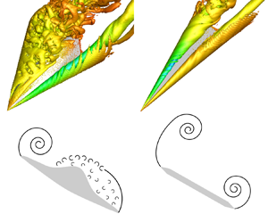
In figure 3(a,c), a representative cycle is selected, and five representative times A–E are marked. The characteristics of the flow field at these times are introduced in the following. Figures 4 and 6 show the flow field of the flying wing and the 80° delta wing, respectively, at four times A, B, C and D (time E is not shown here because it corresponds to the same phase as time A). The flow field of the 65° delta wing at a typical time (t = 1 s) is shown in figure 5. Since the 65° delta wing has almost no oscillation, it is close to the equilibrium position of its free-to-roll motion at this typical time. It can be seen from figure 4 that no right-side LEV is observed above the flying wing during the whole oscillation process, which is like the static situation with  $\phi = 30^\circ $ (figure 8 in the supplementary material). The overall flow structure is always in the form of the ‘vortex–shear layer’. However, the 65° and 80° delta wings always have bilateral LEVs during the oscillation process (figures 5 and 6), which is also like the static situation. Besides the slender delta wings, the flow structures of the flying wing are also different from those of non-slender delta wings. Reference Matsuno and NakamuraMatsuno and Nakamura (2000) and Reference Matsuno, Yokouchi and NakamuraMatsuno et al. (2000) found that at an incidence angle of $\sigma = 30^\circ $, the flow structures of the windward and leeward wing halves of the 45° delta wing significantly change with the variation of the roll angle. At a low roll angle, both the windward wing half and the leeward wing half are globally separated, and no LEV is generated at either half of the wing. As the roll angle increases, only the leeward half of the wing has an LEV, and the breakdown point of the LEV is upstream of the trailing edge. At higher roll angles, the breakdown point of the LEV on the leeward wing half will develop downstream of the trailing edge, while an LEV will be generated on the windward wing half.

Figure 4. Contour of surface pressure coefficient (first row), Q = 15 isosurface coloured by Cp (second row) and Q = 750 isosurface coloured by Cp (third row) of the flying wing at four different moments in Case I.

Figure 5. Contour of surface pressure coefficient (a), Q = 15 isosurface coloured by Cp (b) and Q = 750 isosurface coloured by Cp (c) of the 65° delta wing at a typical moment in Case II.

Figure 6. Contour of surface pressure coefficient (first row), Q = 15 isosurface coloured by Cp (second row) and Q = 750 isosurface coloured by Cp (third row) of the 80° delta wing at four different moments in Case III.
As a supplement, figure 7 shows the surface pressure distribution on different sections of the flying wing and the 80° delta wing at times A, B, C and D, and that of the 65° delta wing at a typical time. The details in figure 7 indicate that the surface pressure distribution of the flying wing has some unique characteristics. For example, due to the leading-edge shape of the flying wing being not strictly sharp, there will be suction peaks caused by flow acceleration near the leading edges on both sides, like the leading-edge suction peak of an airfoil at the pre-stall stage. With the effect of this reverse pressure gradient, the attached flow on both sides eventually separates and forms two shear layers into space, one rolling into the LEV, the other bursting into small-scale structures. In addition, on the x = 0.8c section, the special geometry and flow structure leads to the surface pressure distribution of the flying wing being different from that of the delta wing. Due to the W-shaped trailing edge of the flying wing, there is no longer an entire positive pressure region on the windward surface, but two small negative pressure peaks appear at the connection between the fuselage and the wing, which significantly reduces the lift provided by the rear section. The flow structure evolution and surface pressure variation of the flying wing and delta wings in different phases of free-to-roll oscillation are described in detail below.

Figure 7. Surface pressure distribution of the flying wing (first column), 65° delta wing (second column) and 80° delta wing (third column) on the x = 0.1c section (first row), x = 0.3c section (second row), x = 0.5c section (third row) and x = 0.8c section (fourth row). The first and third columns contain the curves at times A, B, C and D, while the second column contains the curves at a typical moment.
At time A, both the flying wing and the 80° delta wing have rolled to the right-side limit position, i.e.  $\phi ({t_A}) = {\phi _{max}}$. The roll angle keeps increasing before this time and begins to decrease afterward, while the roll angular velocity is close to zero at this moment. In figure 6, the left-side LEV of the 80° delta wing is far away from the wing surface and its strength is weak, and no obvious negative pressure area is induced on the corresponding leeward surface. On the contrary, the right-side LEV is stronger and closer to the surface, which induces an obvious negative pressure area below it. Simultaneously, on the right-side windward surface, there is a strong positive pressure area, especially on sections closer downstream (figure 7). Therefore, the negative pressure on the right-side leeward surface and the positive pressure on the windward surface jointly provide the roll recovery moment of the 80° delta wing at time A, so that the roll angle $\phi (t)$ will decrease after this time. In contrast, for the flying wing, there is no right-side LEV, and therefore there is no obvious concentrated negative pressure area on the right-side leeward surface to provide an effective recovery moment (figure 4). However, figure 7 shows that a strong positive pressure area exists on the right-side windward surface of the flying wing (sections x = 0.1c, 0.3c and 0.5c), thus providing the roll recovery moment to a certain extent. On the other hand, at time A, the strength of the left-side LEV is weakest, which just induces a weak negative pressure area on the corresponding leeward surface, and therefore it is not enough to generate sufficient divergence moment (increase the roll angle). In summary, when the aircraft is located at the right-rolling limit position, the recovery moment of the 80° delta wing is mainly originated from the negative pressure on the sinking-side leeward surface and the positive pressure on the sinking-side windward surface, while the recovery moment of the flying wing is mainly originated from the positive pressure on the sinking-side windward surface and the weakening of the negative pressure on the uplifting-side leeward surface.
At time B and time D, the positions of the flying wing and the 80° delta wing are close to the equilibrium roll angle  ${\phi _0}$. At time B, the aircraft rolls from the right to the left, and $\phi (t)$ is gradually decreasing. At time D, it rolls from the left to the right, and $\phi (t)$ is gradually increasing. It can be seen from figure 4 that the flow field structure and surface pressure distribution of the flying wing at time B and time D are very similar, and the surface pressure at time B and time D has almost no hysteresis (figure 7). This explains the phenomenon that in the ${C_l}$– $\phi $ hysteresis loop, the curves at time B and time D coincide without any hysteresis from the perspective of flow structure. This also provides extra evidence that the hysteresis loop of the flying wing is in the bicyclic form. In comparison, as can be seen from figure 6, the breakdown location of the right-side LEV of the 80° delta wing is upstream of the trailing edge at time B, while the breakdown location of the left-side LEV is downstream of the trailing edge. By contrast, at time D, the breakdown point locations of the LEVs are opposite to those at time B. Therefore, the surface pressure of the 80° delta wing has obvious hysteresis at time B and time D, especially in the negative pressure region induced by the LEVs on the leeward surface, which is also consistent with the situation in the ${C_l}$– $\phi $ hysteresis loop. For the 65° delta wing (figure 5), when the aircraft is near its equilibrium position, the LEVs induce significant negative pressure regions on the leeward side. Since the 65° delta wing has a non-zero equilibrium roll angle, the breakdown point location of the right-side (sinking-side) LEV is closer to the upstream. It can be seen from figure 7 that at different sections, the strength of negative pressure induced by the LEVs on two sides changes alternately due to the influence of the effective angle of attack, LEV breakdown and other factors, maintaining the dynamic balance overall.
At time C, the flying wing and 80° delta wing have rolled to the left limit position, i.e.  $\phi ({t_C}) = {\phi _{min}}$. Due to their different ranges of motion, the roll angle $\phi ({t_C})$ of the flying wing is still greater than 0, while $\phi ({t_C})$ of the 80° delta wing is smaller than 0. For the 80° delta wing, the flow structure currently is approximately mirror-symmetric with that at time A, and the strongest left-side LEV induces a strong negative pressure region on the left-side leeward surface, thus inducing a recovery moment that tends to reduce the absolute value of the roll angle. The flying wing also has the strongest left-side LEV at time C, which therefore induces the strongest negative pressure area on the corresponding leeward surface, resulting in a roll divergence moment and making the roll angle $\phi (t)$ begin to increase after this time. However, on the right-side leeward surface of the flying wing, there is also the strongest negative pressure currently (figure 7), while the positive pressure on the right-side windward surface is basically the same as that at time A. This shows that the right-half wing of the flying wing provides a recovery moment, which is opposite to the divergence moment originating from the left-half wing. Since the divergence moment from the left-half wing is larger than the recovery moment from the right-half wing, the net moment is still the divergence moment. Therefore, the roll angle $\phi (t)$ will increase after this time.
From the above discussions, it is evident that the flying wing and the delta wing have different dominant flow structures. In summary, at high roll angles, whether for static or dynamic cases, the flying wing has a vortex–shear-layer system, while the delta wing has a vortex–vortex system. This difference in mechanism is visually illustrated in figure 8, in which the flow structures on an x section are shown. In the wing rock motion, the oscillation of the flying wing depends on the mutual interactions between the LEV on the uplifting side and the separated shear layer on the sinking side, while the oscillation of the delta wing is driven by the two LEVs. Therefore, there are obvious differences between their equilibrium position, motion range and hysteresis characteristic.

Figure 8. Schematic diagram of dominant flow structures of the flying wing (a) and the delta wing (b) at large roll angles.
The difference in flow structures between the flying wing and the delta wings in the wing rock motion is qualitatively analysed above. However, quantitative analysis of the evolution of the LEV and separated shear layer is very important for an in-depth understanding of the driving mechanism of the different wing rock mode of the flying wing. In previous research on the driving mechanism of the delta wing's wing rock, the hysteresis of the LEV's strength and vortex-core position are significant factors (Reference ArenaArena, 1990, Reference Arena1992; Reference Jun and NelsonJun & Nelson, 1988; Reference Nelson and PelletierNelson & Pelletier, 2003). Therefore, this study also focuses on the circulation, normal position and spanwise position of the LEV and shear layer on different sections of the flying wing and the 80° delta wing. The specific definitions of these physical quantities (including  ${\varGamma ^ + }$, ${z^ + }$, ${y^ + }$, ${\varGamma ^ - }$, ${z^ - }$ and ${y^ - }$) are provided in Appendix H of the supplementary material. Reference ArenaArena (1992) studied in detail how the hysteresis of the LEV-related quantities drives the wing rock motion of the 80° delta wing and proved that the hysteresis of these quantities is crucial in the self-sustained oscillation. However, based on the characteristics of the flow structure of the 80° delta wing, i.e. the vortex–vortex system, Reference ArenaArena (1992) only focused on the changes of circulation and location of the LEV itself but did not consider the leading-edge shear layer connected with the LEV. By contrast, in this study, the calculations of these physical quantities include both the LEV and the leading-edge shear layer. This method is attributed to the characteristics of the flow structure of the flying wing, i.e. the vortex–shear-layer system. These definitions can more accurately reflect the difference in the flow field evolution between the flying wing and the delta wing during the wing rock.
Figures 9 and 10 show the total circulation and vorticity centroid position of the left-side positive vorticity and the right-side negative vorticity of the flying wing and the 80° delta wing, respectively. Many previous studies have shown that the wing rock motion can be considered as superimposing additional dynamic hysteresis to the flow field structure/aerodynamic loads of the static rolling model, and is affected by some critical flow events (Reference ArenaArena, 1992; Reference Jenkins, Myatt and HanffJenkins et al., 1993; Reference Pelletier and NelsonPelletier & Nelson, 2000). Therefore, in the following analysis, the influence of these LEV-related physical quantities on wing rock motion is discussed from two aspects: static roll stability/instability and dynamic hysteresis. Inspired by the spring–mass model (summarized by Reference KatzKatz, 1999), a less strict but simple way is to regard the variation in these physical quantities with the roll angle  $\phi (t)$ as the influence on the static rolling stability, while their variation with the sign of roll angular velocity $\dot{\phi }(t)$ as the influence on the dynamic damping. Although this method ignores the influence of high-order terms such as roll angular acceleration (which mainly causes added-mass force), it is beneficial for intuitively understanding the complex nonlinear wing rock motion.

Figure 9. Variation in the respective (a,d) circulation, (b,e) normal centroid position and (c,f) spanwise centroid position of the positive (a–c) and negative (d–f) vorticities with the roll angle, on different sections of the flying wing in Case I.

Figure 10. Variation in the respective (a,d) circulation, (b,e) normal centroid position and (c,f) spanwise centroid position of the positive (a–c) and negative (d–f) vorticities with the roll angle, on different sections of the 80° delta wing in Case III.
For the 80° delta wing, the increase of  $|{\varGamma ^ + }|$ means that the left-side LEV becomes stronger, which will induce a stronger negative pressure on the left-side leeward surface. Therefore, the increase of $|{\varGamma ^ + }|$ favours increasing the local lift on the left-hand side, so that the aircraft rolls to right and the roll angle $\phi (t)$ increases. The effect of $|{\varGamma ^ - }|$ is just opposite to that of $|{\varGamma ^ + }|$. For the flying wing, the effect of $|{\varGamma ^ + }|$ is the same as that for the 80° delta wing, that is, the increase of $|{\varGamma ^ + }|$ favours increasing the roll angle $\phi (t)$. However, considering that the right-side shear layer of the flying wing transits before reaching the trailing edge and no concentrated negative pressure area is induced on the wing surface by it (figures 4 and 7), it is difficult to prove the direct causal relationship between the shear layer or these small-scale turbulent structures and the surface pressure. Therefore, the influence of $|{\varGamma ^ - }|$ on the flying wing's wing rock is unclear. As can be seen from figure 9(a,d), both $|{\varGamma ^ + }|$ and $|{\varGamma ^ - }|$ of the flying wing decrease with an increase in $\phi (t)$, which is different from the symmetry situation of the 80° delta wing (figure 10a,d). The negative slope of $|{\varGamma ^ + }|$ versus $\phi (t)$ indicates that the variation in $|{\varGamma ^ + }|$ always tends to prevent the change in $\phi (t)$, whether an increase or decrease. Therefore, variation in $|{\varGamma ^ + }|$ with $\phi (t)$ of the flying wing always provides static roll stability. In comparison, whether $|{\varGamma ^ + }|$ and $|{\varGamma ^ - }|$ of the 80° delta wing provide stability or instability depends on the range of $\phi (t)$.
In the process of oscillation, the variation in  $|{\varGamma ^ + }|$ and $|{\varGamma ^ - }|$ with the sign of roll angular velocity $\dot{\phi }(t)$ should also be specially considered. In previous studies of the 80° delta wing, the hysteresis effect of the LEV's circulation is an important factor in maintaining the wing rock oscillation, which provides damping at large roll angles and prevents the roll angle from being divergent (Reference Nelson and PelletierNelson & Pelletier, 2003). Therefore, in the tricyclic ${C_l}$– $\phi $ hysteresis loop of the delta wing, the two small loops far from the equilibrium roll angle position ${\phi _0}$, which are called ‘damping lobes’, are counterclockwise, representing net damping. A similar conclusion for the 80° delta wing is also obtained in the present case (figure 10a,d). As can be seen, at large roll angles, the LEV closer to the wing surface (on the sinking side) has a more apparent hysteresis, with a damping effect generated. However, for the flying wing, $|{\varGamma ^ + }|$ has a very weak hysteresis throughout the oscillation cycle (figure 9a). This shows that the circulation hysteresis of the LEV has a limited effect on the maintenance of wing rock motion of the flying wing, which is different from the situation for the 80° delta wing. Moreover, it can be seen from figure 9(a) that the weak hysteresis of $|{\varGamma ^ + }|$ produces weak negative damping rather than positive damping, which is contrary to the hysteresis effect of LEV circulation of the 80° delta wing. Therefore, the flying wings cannot form damping lobes at large roll angles, and therefore do not have a tricyclic hysteresis loop like the delta wing.
If other conditions remain unchanged, an increase in the normal position of the vortex core means that the LEV is far away from the wing, and the negative pressure induced by it on the wing surface will be reduced accordingly. Therefore, an increase in  $|{z^ + }|$ favours reducing the roll angle $\phi (t)$ of the flying wing/delta wing, while an increase in $|{z^ - }|$ favours increasing $\phi (t)$ of the delta wing. In figure 9(b,e), $|{z^ + }|$ of the flying wing is weakly dependent on $\phi (t)$, which indicates that the change of $|{z^ + }|$ has a weak effect on the static roll stability/instability. In addition, like $|{\varGamma ^ - }|$, the influence of $|{z^ - }|$ on the flying wing's wing rock is also unclear. By comparison, the variation of $|{z^ + }|$ and $|{z^ - }|$ with $\phi (t)$ of the delta wing contributes to a static stable moment in most stages of motion (figure 10b,e). On the other hand, the dynamic hysteresis of the LEV's normal position plays an important role in the wing rock motion of the flying wing and delta wing. For the 80° delta wing, there is a significant hysteresis of the LEV's normal centroid position during the oscillation process (figure 10b,e), and the hysteresis is strong enough to generate instability to overcome the damping moment at high speed. Therefore, the hysteresis of the normal position of bilateral LEVs is a significant factor driving the maintenance of self-induced oscillation of the delta wing. It can be seen from figure 9(b) that $|{z^ + }|$ of the flying wing also has an obvious hysteresis, and it generates negative damping to drive the wing rock oscillation, so it is also an essential factor to maintain the self-induced oscillation. However, the difference between the flying wing and the 80° delta wing is that the LEV of the delta wing has an obvious hysteresis only when it is far from the wing surface (on the uplifting side), while the LEV of the flying wing has a significant hysteresis throughout the cycle.
For both the flying wing and delta wing, if the strength and the normal position of the LEV remain unchanged, the variation in its spanwise position will cause variation in the length of the arm of force. Therefore, an increase of  $|{y^ + }|$ means that the left-side LEV is far away from the symmetry plane of the fuselage, thus increasing the rightward roll moment and increasing the roll angle $\phi (t)$. As can be seen from figure 9(c), $|{y^ + }|$ of the flying wing increases with an increase in $\phi (t)$, so it favours a static roll divergence moment. Similarly, $|{y^ + }|$ and $|{y^ - }|$ of the 80° delta wing also favour roll divergence (figure 10c,f). However, the spanwise position of the 80° delta wing's LEV varies widely, while that of the flying wing is relatively limited. This is because the bulge on the leeward surface of the flying wing limits the movement space of the LEV and the shear layer. This is also one of the unique flow-field characteristics of the flying wing. On the other hand, the hysteresis of the spanwise position of the LEV of the flying wing and delta wing is very weak and can be ignored, which also indicates that the effect of the spanwise position variation of the LEVs on the dynamic damping can be ignored.
In summary, in the analysis results of the present study, the variation laws of the LEV-related physical quantities of the 80° delta wing are consistent with results reported previously (Reference GursulGursul, 2005; Reference KatzKatz, 1999; Reference MabeyMabey, 1997; Reference Nelson and PelletierNelson & Pelletier, 2003). However, the variation laws of the LEV-related quantities of the flying wing have many unique characteristics different from those of the delta wing. To facilitate the comparison of the differences between the flying wing and the 80° delta wing, table 2 summarizes the effects of the three physical quantities  $|{\varGamma ^ + }|$, $|{z^ + }|$ and $|{y^ + }|$ on the static roll stability and dynamic damping. For the 80° delta wing, due to the symmetry, the effects of $|{\varGamma ^ - }|$, $|{z^ - }|$ and $|{y^ - }|$ are the same, while for the flying wing, the effects of $|{\varGamma ^ - }|$, $|{z^ - }|$ and $|{y^ - }|$ are vague. Besides the physical quantities discussed above, another factor that affects the wing rock is the streamwise breakdown position of the LEV. The change of vortex breakdown position of the 80° delta wing usually leads to a damping effect (Reference ArenaArena, 1990). However, it can be seen from figure 4 that the left-side LEV breakdown point of the flying wing never develops to the upstream of the trailing edge, so it does not have a direct impact on the surface pressure, and its effect on the wing rock can be ignored.
Table 2. Effects of the LEV-related physical quantities on the static roll stability and dynamic damping during wing rock oscillation.

5. Conclusions
The wing rock phenomenon for a flying wing model with a sweep angle of 65° are studied by using wind tunnel experiment and numerical simulation. The experiment focuses on the flying wing's wing rock motion under different angles of attack and free-stream velocities, and the numerical simulation compares the difference between the flying wing, the 65° delta wing and the 80° delta wing under static and dynamic conditions and exhibits the spatial–temporal evolution of their dominant flow structures. Both the experimental and numerical results show that the flying wing has a bicyclic  ${C_l}$– $\phi $ hysteresis loop during its wing rock, different from other aircraft, such as the slender delta wing, rectangular wing and generic aircraft configuration, which have a tricyclic hysteresis loop. This form of hysteresis loop represents a different energy exchange manner in the wing rock motion. Further analysis shows that the flying wing can only form a unilateral LEV under a high roll angle, and its wing rock is driven by a vortex–shear-layer system, different from that of the slender and non-slender delta wings. A quantitative analysis of the LEV-related physical quantities, such as the circulation and vorticity centroid position of the LEV, shows that some hysteresis characteristics of the flying wing's flow structure are different from those of the slender delta wing, which leads to the difference between their wing rock motion. These results have proven the existence of a different wing rock mode and revealed its flow mechanism, which enriches the understanding of the classical physical problem of wing rock. This study is also conducive to aerodynamic shape design and flight manipulation of the flying wing. However, the present study only focuses on the wing rock phenomenon of a flying wing aircraft at a low-speed uncompressible condition. The influence of various parameters, such as the Mach number, Reynolds number and moment of inertia, on the flying wing's lateral instability needs further research.
Supplementary material
Supplementary material is available at https://doi.org/10.1017/flo.2023.30. Raw data are available from the corresponding author.
Funding statement
This study was supported by the National Natural Science Foundation of China (grant nos U2141253 and 11721202).
Declaration of interests
The authors report no conflict of interest.
Author contributions
Conceptualization: X.L., L.-H.F. Data curation: X.L. Formal analysis: X.L., L.-H.F. Funding acquisition: L.-H.F. Investigation: X.L., L.-H.F., Q.-M.W. Methodology: X.L., L.-H.F. Project administration: X.L., L.-H.F. Software: X.L. Validation: X.L., Q.-M.W. Visualization: X.L., L.-H.F. Writing – original draft: X.L. Writing – review and editing: X.L., L.-H.F.


 Open access