


1. Introduction
The ultrafast dynamics of electrons and nuclei in atoms and molecules are crucial in describing their interaction with matter and light[ Reference Stolow, Bragg and Neumark1]. These dynamics occur over timescales ranging from picoseconds for nuclei to attoseconds for electrons[ Reference Yamanouchi2– Reference Xie, Doblhoff-Dier, Roither, Schöffler, Kartashov, Xu, Rathje, Paulus, Baltuška, Gräfe and Kitzler8]. In many applications, the use of ultrashort pulses is necessary to initiate and investigate specific dynamics through a pump–probe scheme. Typically, the temporal resolution of such pump–probe experiments depends on the pulse duration of both the pump and probe pulses. Therefore, achieving the required temporal resolution to resolve ultrafast dynamics in the time domain necessitates pump–probe pulses with comparable or shorter duration. Currently, mode-locked optical lasers and free-electron lasers (FELs) are routinely employed to generate ultrashort pulses, covering a broad spectral range from THz to hard X-rays[ Reference Fermann, Galvanauskas and Sucha9– Reference Seddon, Clarke, Dunning, Masciovecchio, Milne, Parmigiani, Rugg, Spence, Thompson, Ueda, Vinko, Wark and Wurth11]. Optical laser pulses can be delivered with durations as short as a few femtoseconds in the visible and near-infrared spectral range. These laser pulses can also be used to generate attosecond pulses in the extreme ultraviolet (UV)/soft X-ray spectral range through high-order harmonic generation[ Reference Krausz and Ivanov3].
Femtosecond pulses in the violet and UV spectral range can be generated through low-order harmonic generation of near-infrared femtosecond laser pulses from a Ti:sapphire or Yb-based laser amplifier. These violet and UV pulses find a wide range of applications in fields such as physics, chemistry, biology and materials science, enabling the investigation of ultrafast processes occurring on picosecond and femtosecond timescales. Time-resolved violet and UV spectroscopy with sub-hundred femtosecond pulses provides access to processes involving nuclear dynamics in chemical reactions and biological phenomena. To resolve ultrafast proton or electron dynamics, violet and UV pulses with durations below 10 fs are required[ Reference Hanus, Kangaparambil, Larimian, Dorner-Kirchner, Xie, Schöffler, Paulus, Baltuška, Staudte and Kitzler-Zeiler12]. However, the violet and UV pulse duration in low-order harmonic generation is limited by the bandwidths of the near-infrared fundamental pulses, which generally support pulse durations of only tens of femtoseconds.
Sub-10 fs pulses with sufficient pulse energy are also useful for nonlinear optics applications. For example, previous experiments have demonstrated that high harmonic generation with millijoule 400 nm pulses significantly increases the conversion efficiency compared to 800 nm pulses[ Reference Falcão-Filho, Lai, Hong, Gkortsas, Huang, Chen and Kärtner13]. Simulations have indicated that isolated attosecond pulses can be generated using a 6.5 fs 400 nm pulse with a double optical gating technique[ Reference Khan, Cheng, Möller, Zhao, Zhao, Chini, Paulus and Chang14]. Therefore, a millijoule-level sub-10 fs violet and UV pulse can serve as the driving source for generating intense isolated attosecond pulses through high harmonic generation.
The sub-10 fs regime in the violet and UV spectral range can be reached with subsequent spectral broadening and post-compression in addition to the low-order harmonic generation process. Spectral broadening is usually achieved through the effect of self-phase modulation (SPM), which occurs when strong laser pulses interact with a nonlinear medium, such as gases or transparent solids[
Reference Dubietis, Tamošauskas, Šuminas, Jukna and Couairon15,
Reference Boyd16]. SPM is a time-domain Kerr effect, where the third-order nonlinear susceptibility of a medium introduces an effective index of refraction ${n}_{\mathrm{eff}}$
that depends on the pulse intensity
${n}_{\mathrm{eff}}$
that depends on the pulse intensity $I(t)$
, given by
$I(t)$
, given by $n = {n}_0+{n}_2I(t)$
, where
$n = {n}_0+{n}_2I(t)$
, where ${n}_0$
represents the linear index of refraction. For most materials,
${n}_0$
represents the linear index of refraction. For most materials, ${n}_2$
is greater than zero, resulting in a lower phase velocity at the center of an ultrashort pulse compared to its edges. Consequently, new frequencies are generated throughout the pulse as it propagates through the medium. This approach is widely employed for spectral broadening and post-compression of laser pulses across a spectral range spanning from UV to mid-infrared[
Reference Nagy, Simon and Veisz17].
${n}_2$
is greater than zero, resulting in a lower phase velocity at the center of an ultrashort pulse compared to its edges. Consequently, new frequencies are generated throughout the pulse as it propagates through the medium. This approach is widely employed for spectral broadening and post-compression of laser pulses across a spectral range spanning from UV to mid-infrared[
Reference Nagy, Simon and Veisz17].
The most commonly used techniques for achieving sub-10 fs pulse durations in the violet and UV spectral range rely on SPM in gas-filled waveguides[ Reference Nisoli, De Silvestri and Svelto18– Reference Chang, Zürch, Kraus, Borja, Neumark and Leone26]. Nibbering et al. [ Reference Nibbering, Korn, Tempea and Krausz20] obtained 15 μJ, 8 fs, 400 nm pulses with spectrum broadening in a gas-filled hollow-core capillary. Similarly, Liu et al. [ Reference Liu, Okamura, Kida, Teramoto and Kobayashi23, Reference Liu, Kida, Kobayashi and Teramoto24] achieved 45 μJ output energy with a pulse duration of 7.5 fs at around 400 nm. Cheng et al. [ Reference Cheng, Khan, Zhao, Zhao, Chini and Chang25] realized sub-10 fs, 500 μJ output at 400 nm using a gas-filled hollow-core fiber with an input pulse energy of 1 mJ. However, these pulse post-compression techniques based on gas-filled waveguides have some disadvantages. Firstly, fluctuations and long-term changes in gas pressure inside the waveguides can introduce significant timing fluctuations and drift in the laser arrival time, which can be problematic for applications requiring timing stability, such as pump–probe experiments at FEL facilities. In addition, gas-filled waveguide setups are generally implemented in vacuum systems, adding bulk and complexity to the experimental setup. A newly developed all-solid free-space technique based on multi-plate spectral broadening can overcome these disadvantages[ Reference Lu, Tsou, Chen, Chen, Cheng, Yang, Chen, Hsu and Kung27– Reference Zhang, Fu, Zhu, Fan, Chen, Wang, Liu, Baltuska, Jin, Tian and Tao37]. This technique utilizes thin fused-silica plates with thicknesses of a few hundred micrometers to broaden the spectrum of the input pulse through cascaded SPM while avoiding breakdown and spatial distortion in the medium due to self-focusing and conical diffraction[ Reference Couairon and Mysyrowicz38, Reference Cheng, Lu, Lin and Kung39]. Liu et al. [ Reference Liu, Zhao, He, Huang, Teng and Wei30] used eight thin glass plates in a single pass to broaden the spectrum of 400 nm pulses and compressed them to 8.6 fs with a pulse energy of 120 μJ. More recently, Hu et al. [ Reference Hu, Zhang, Cao, Hong, Cao and Lu40] generated 7.8 μJ, 5.2 fs, 400 nm pulses using a two-stage thin-plate setup. In addition to the techniques based on SPM, there are other methods available for generating broadband violet pulses through second harmonic generation (SHG). Szabó and Bor[ Reference Szabó and Bor41], Kanai et al. [ Reference Kanai, Zhou, Sekikawa, Watanabe and Togashi42] and Zhou et al. [ Reference Zhou, Kanai, Yoshitomi, Sekikawa and Watanabe43] employed a frequency domain SHG technique, which allowed for broadband frequency doubling, and they obtained a 7.5 fs 400 nm pulse with a pulse energy of 320 μJ. Here in this work, we demonstrate the generation of a millijoule-level broadband violet pulse using a single optical component for the SHG in a thin beta barium borate (BBO) crystal and SPM of the second harmonic beam in the fused-silica substrate of the crystal, and further pulse post-compression down to sub-5 fs pulse duration using a chirped-mirror compressor.
2. Experiments
A schematic view of the experimental setup is presented in Figure 1. The fundamental pulses are delivered from a Ti:sapphire laser amplifier (Coherent Legend Elite Duo HE+) with the following specifications: a center wavelength of 800 nm, a pulse energy of 20 mJ, a repetition rate of 100 Hz and a pulse duration of 30 fs. The beam diameter at $1/{e}^2$
intensity is 18 mm. After a beam splitter, a portion of the laser beam with a pulse energy of 8.1 mJ is focused by a lens with a focal length of 750 mm. A thin type I BBO crystal with a thickness of 50 μm and a clear aperture of 10 mm on a 2 mm fused-silica substrate (BBO on the front side) is placed after the lens and before the focus for SHG. After the BBO crystal, a broadband wavelength separator (high reflection from 350 to 450 nm and high transmission from 700 to 900 nm) is used to isolate the second harmonic beam. To avoid damage to the optical components, the BBO crystal is kept at a minimum distance of 150 mm in front of the laser focus. After the wavelength separator, the second harmonic beam is re-collimated with a silver concave mirror with a focal length of 500 mm and bounced eight times between pairs of chirped mirrors (Ultrafast Innovations CM82, bandwidth, 350–450 nm; nominal group-delay dispersion (GDD) per bounce, –40 fs2) to introduce negative group-velocity dispersion (GVD). Final compression is achieved upon transmission through a pair of uncoated fused-silica wedges, where the optical path length of the second harmonic beam through the glass wedges can be tuned to compensate residual GVD. Finally, the compressed second harmonic beam is sent to a self-diffraction frequency-resolved optical gating (SD-FROG) device for the pulse duration characterization[
Reference Trebino44]. The output spectrum is measured using a grating spectrometer. In the experiment, the grating compressor of the fundamental beam from the Ti:sapphire amplifier was tuned to deliver the shortest pulse at the BBO/fused-silica plate to achieve the broadest spectrum of the second harmonic.
$1/{e}^2$
intensity is 18 mm. After a beam splitter, a portion of the laser beam with a pulse energy of 8.1 mJ is focused by a lens with a focal length of 750 mm. A thin type I BBO crystal with a thickness of 50 μm and a clear aperture of 10 mm on a 2 mm fused-silica substrate (BBO on the front side) is placed after the lens and before the focus for SHG. After the BBO crystal, a broadband wavelength separator (high reflection from 350 to 450 nm and high transmission from 700 to 900 nm) is used to isolate the second harmonic beam. To avoid damage to the optical components, the BBO crystal is kept at a minimum distance of 150 mm in front of the laser focus. After the wavelength separator, the second harmonic beam is re-collimated with a silver concave mirror with a focal length of 500 mm and bounced eight times between pairs of chirped mirrors (Ultrafast Innovations CM82, bandwidth, 350–450 nm; nominal group-delay dispersion (GDD) per bounce, –40 fs2) to introduce negative group-velocity dispersion (GVD). Final compression is achieved upon transmission through a pair of uncoated fused-silica wedges, where the optical path length of the second harmonic beam through the glass wedges can be tuned to compensate residual GVD. Finally, the compressed second harmonic beam is sent to a self-diffraction frequency-resolved optical gating (SD-FROG) device for the pulse duration characterization[
Reference Trebino44]. The output spectrum is measured using a grating spectrometer. In the experiment, the grating compressor of the fundamental beam from the Ti:sapphire amplifier was tuned to deliver the shortest pulse at the BBO/fused-silica plate to achieve the broadest spectrum of the second harmonic.
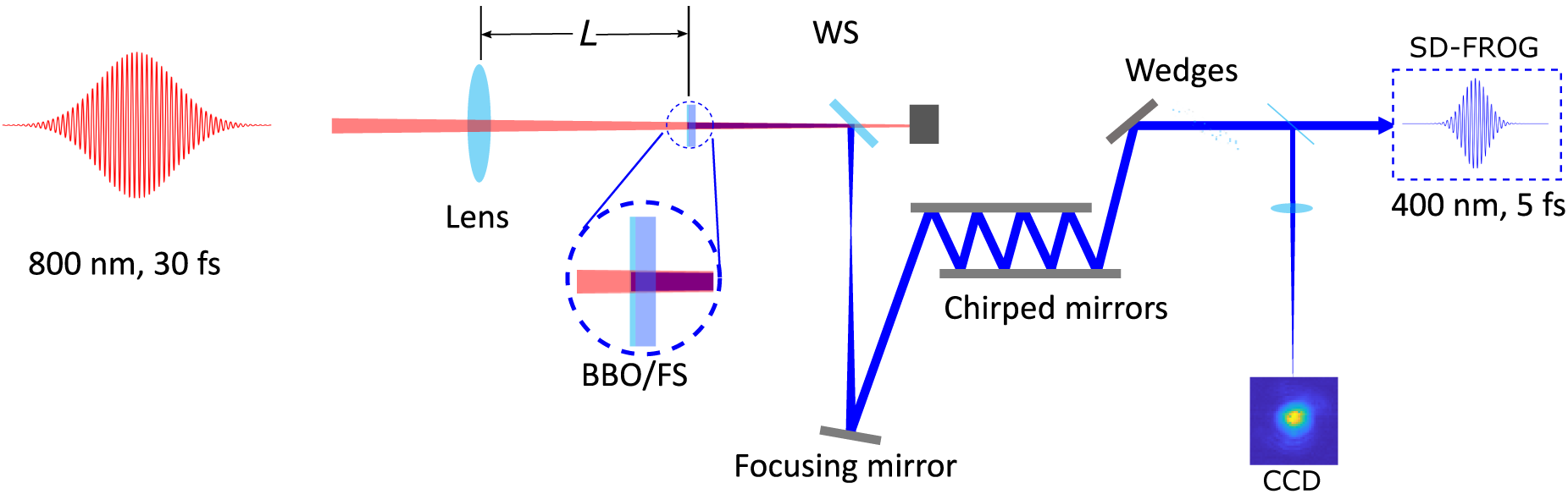
Figure 1 A schematic view of the experimental setup (WS, wavelength separator; FS, fused silica). The 800 nm beam is focused by a convex lens to the BBO crystal and its substrate. Afterward, the second harmonic beam is isolated and collimated before being sent to a chirped-mirror compressor. The beam profile was measured at the focus of an uncoated fused-silica lens with a focal length of 500 mm.
3. Results and discussion
3.1. Second harmonic generation and self-phase modulation
SHG and SPM are second- and third-order nonlinear processes, respectively. Therefore, the laser intensity plays a critical role in their efficiency. Efficient harmonic generation and effective spectral broadening due to SPM can only occur when the laser intensity is sufficient. In the experiment, an 800 nm laser beam was focused with a 750 mm focal length convex lens and the position of the lens was scanned with respect to the BBO/fused-silica plate to vary the laser intensity. The resultant SHG is characterized for different input intensities in Figure 2. The spectral dependence on input intensity (or distance L from the focusing lens) is shown in Figure 2(a). The integrated SHG signal strength and the SHG bandwidth at full width at half maximum (FWHM) are shown in Figure 2(b). When the BBO crystal is closer to the laser focus (increasing L) with higher intensity, a second harmonic beam with monotonically increasing signal intensity and bandwidth is observed. The signal intensity of the second harmonic beam can be increased by a factor of 4 until saturation, which is reached when L approaches 600 mm, with a corresponding pulse energy of 1.5 mJ measured after the wavelength separator. In the distance range between 350 and 600 mm, the bandwidth of the second harmonic signal increases quadratically.
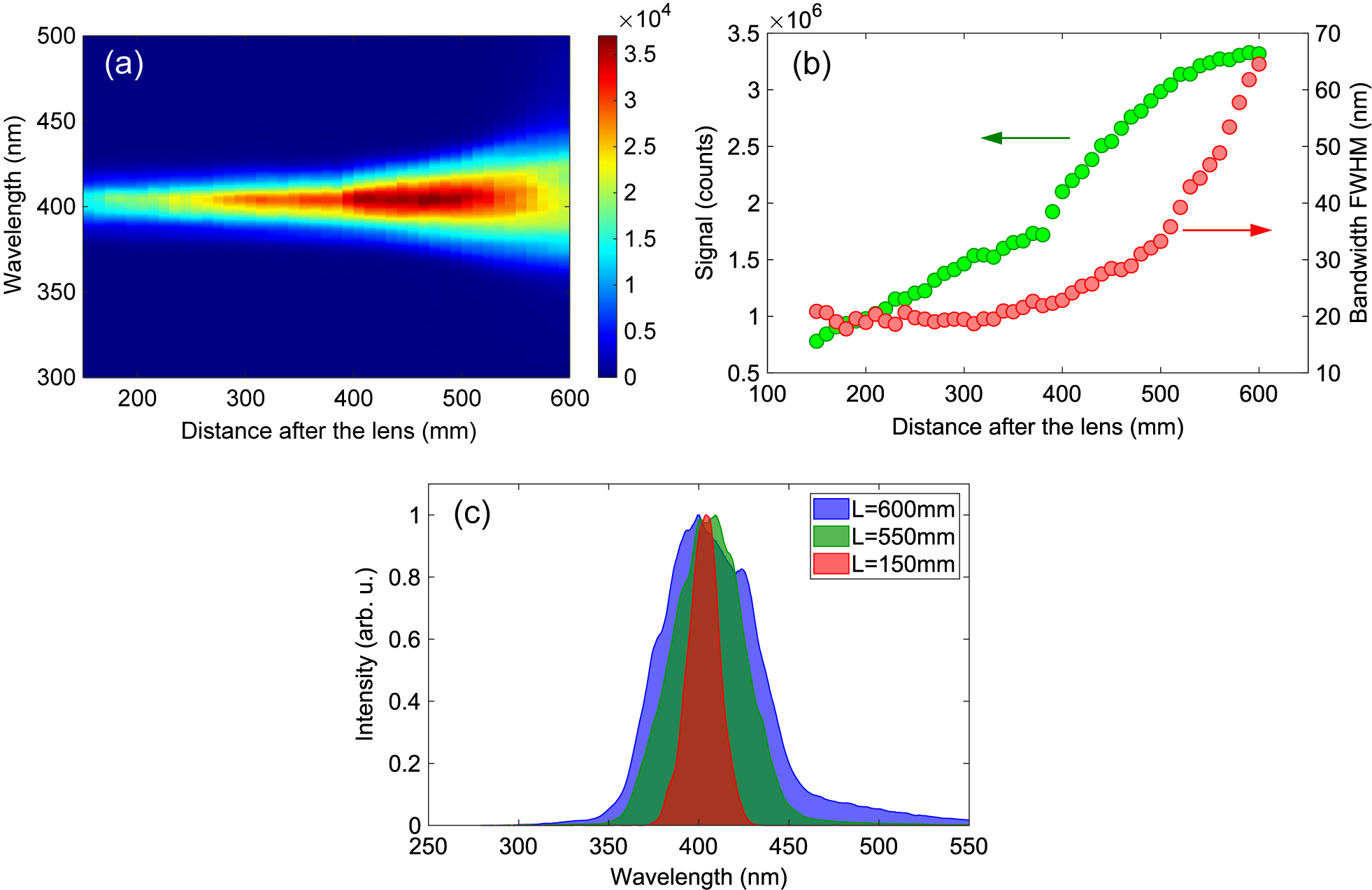
Figure 2 (a) Measured spectrum distribution as a function of the BBO position with respect to the focusing lens. (b) The bandwidth (FWHM) and the signal intensity of the second harmonic beam as a function of the BBO position with respect to the focusing lens. (c) Measured spectra of the second harmonic beam for three different BBO positions.
The individual spectra of the second harmonic at three different positions are depicted in Figure 2(c). When the BBO crystal is far from the focus with L = 100 mm, the peak laser intensity (the maximum pulse intensity at the beam center) of the fundamental beam is approximately $2.7\times {10}^{11}$
W/cm2, and the spectral width of the second harmonic beam is about 19 nm, which is the same as that obtained with an unfocused fundamental beam. The onset of SPM occurs around L = 350 mm, corresponding to a peak laser intensity of
$2.7\times {10}^{11}$
W/cm2, and the spectral width of the second harmonic beam is about 19 nm, which is the same as that obtained with an unfocused fundamental beam. The onset of SPM occurs around L = 350 mm, corresponding to a peak laser intensity of $1.3\times {10}^{12}$
W/cm2 for the second harmonic beam in the fused silica. When the BBO crystal is moved to L = 500 mm, the spectrum becomes broader with an FWHM of 47 nm. The spectral bandwidth reaches 65 nm FWHM when L = 600 mm, which is significantly broader than that obtained with an unfocused beam, by a factor of more than 3. The fundamental beam is approximately 3.6 mm in diameter at L = 600 mm, resulting in a peak laser intensity of about
$1.3\times {10}^{12}$
W/cm2 for the second harmonic beam in the fused silica. When the BBO crystal is moved to L = 500 mm, the spectrum becomes broader with an FWHM of 47 nm. The spectral bandwidth reaches 65 nm FWHM when L = 600 mm, which is significantly broader than that obtained with an unfocused beam, by a factor of more than 3. The fundamental beam is approximately 3.6 mm in diameter at L = 600 mm, resulting in a peak laser intensity of about $5\times {10}^{12}$
W/cm2 in the BBO. In the case of unsaturated SHG, the beam size of the second harmonic beam would be smaller than that of the fundamental beam with a ratio of
$5\times {10}^{12}$
W/cm2 in the BBO. In the case of unsaturated SHG, the beam size of the second harmonic beam would be smaller than that of the fundamental beam with a ratio of $\sqrt{2}$
. However, as indicated in Figure 2(b), the SHG is in saturation, and the diameter of the second harmonic beam is therefore larger than 2.6 mm. Taking the beam diameter into account and with a pulse energy of 1.5 mJ, the intensity of the second harmonic beam in the fused silica is estimated to be lower than
$\sqrt{2}$
. However, as indicated in Figure 2(b), the SHG is in saturation, and the diameter of the second harmonic beam is therefore larger than 2.6 mm. Taking the beam diameter into account and with a pulse energy of 1.5 mJ, the intensity of the second harmonic beam in the fused silica is estimated to be lower than $1.8\times {10}^{12}$
W/cm2 (assuming a pulse duration of 30 fs for the second harmonic beam after the BBO crystal). To avoid damage to the BBO crystal and its substrate, the BBO at the position was kept with L = 600 mm and the broadened second harmonic emission was used for subsequent pulse compression.
$1.8\times {10}^{12}$
W/cm2 (assuming a pulse duration of 30 fs for the second harmonic beam after the BBO crystal). To avoid damage to the BBO crystal and its substrate, the BBO at the position was kept with L = 600 mm and the broadened second harmonic emission was used for subsequent pulse compression.
Intuitively, two possible scenarios can explain the spectral broadening of the second harmonic in the experiment. The first scenario involves a single step in which SHG and spectral broadening occur in the BBO crystal itself. The second scenario involves two steps: SHG in the BBO crystal and then spectral broadening of the SHG in the fused-silica substrate. To rule out the first scenario, the second harmonic spectrum was measured from a free-standing 100 μm BBO crystal without a substrate at the high-intensity position of L = 600 mm. The spectral width of the second harmonic is about 19 nm (FWHM), which matches the unbroadened spectral width obtained when using the 50 μm BBO/fused-silica plate at low intensity. This observation implies that there is no spectral broadening of the second harmonic signal in the BBO crystal. Therefore, it is found that spectral broadening occurs in the fused-silica substrate after the generation of the second harmonic beam from the BBO crystal. This conclusion is further supported by the fact that similar spectral broadening is also achieved when using the 100 μm free-standing BBO crystal at L = 400 mm and a 2 mm fused-silica plate placed afterward at L = 600 mm. Furthermore, the quadratic increase of the bandwidth as a function of the distance $L$
after the lens, shown in Figure 2(b), can be explained by SPM. The spectrum broadening of SPM is proportional to the Kerr effect induced phase shift, which is expressed by the so-called B-integral:
$L$
after the lens, shown in Figure 2(b), can be explained by SPM. The spectrum broadening of SPM is proportional to the Kerr effect induced phase shift, which is expressed by the so-called B-integral: $B = 2\pi {n}_2 Il/{\lambda}_0$
, where
$B = 2\pi {n}_2 Il/{\lambda}_0$
, where ${\lambda}_0$
is the central wavelength,
${\lambda}_0$
is the central wavelength, $I$
represents the laser peak intensity and
$I$
represents the laser peak intensity and $l$
is the thickness of the nonlinear medium[
Reference Nagy, Simon and Veisz17]. The SHG signal exhibits a linear increase as a function of the distance
$l$
is the thickness of the nonlinear medium[
Reference Nagy, Simon and Veisz17]. The SHG signal exhibits a linear increase as a function of the distance $L$
before saturation, as shown in Figure 2(b). On the other hand, the lens has a focusing effect that reduces the beam size and increases the laser peak intensity linearly with
$L$
before saturation, as shown in Figure 2(b). On the other hand, the lens has a focusing effect that reduces the beam size and increases the laser peak intensity linearly with $L$
. As a result, the peak intensity of the SHG beam inside the substrate increases quadratically as a function of the distance
$L$
. As a result, the peak intensity of the SHG beam inside the substrate increases quadratically as a function of the distance $L$
, leading to the quadratic increase of the bandwidth induced by SPM.
$L$
, leading to the quadratic increase of the bandwidth induced by SPM.
Besides SPM, cross-phase modulation (XPM) can also contribute to spectral broadening, where the phase of the second harmonic beam is modulated by the Kerr effect induced by the 800 nm beam[ Reference Alfano and Ho45]. To evaluate the potential contribution from XPM, the broadened spectrum of the second harmonic beam was measured using the 100 μm free-standing BBO crystal with a wavelength separation after the BBO and a 2 mm fused-silica plate at L = 600 mm. In this case, only the second harmonic beam is present in the fused silica. The measured spectrum is about 62 nm, which is 3 nm narrower than the spectrum without the wavelength separation. This difference can be attributed to a minor effect of XPM. The fact that XPM plays only a minor role can be explained by the group-velocity mismatch between the fundamental and second harmonic beams (approximately 10 fs delay from the 50 μm BBO and 55 fs for each millimeter of fused silica). Therefore, the spectral broadening of the second harmonic beam in the experiment predominantly occurs due to SPM in the 2 mm fused-silica substrate.
3.2. Pulse compression using chirped mirrors
For the pulse compression, the second harmonic beam generated with the 50 μm BBO and 2 mm fused-silica substrate placed at a distance L = 600 mm from the 750 mm focusing lens was first collimated with a concave mirror. In this case, the SHG bandwidth is approximately 65 nm FWHM. The collimated second harmonic beam is sent through the chirped-mirror compressor, consisting of eight bounces on chirped mirrors with approximately –40 fs2 GDD per bounce, which also further removes the residual fundamental beam. Finally, the beam is passed through the dispersion compensation wedge pair and then directed into an SD-FROG for pulse characterization. Using an iterative phase retrieval algorithm, the temporal shape of the measured pulse is reconstructed from the measured FROG trace[ Reference Kane and Trebino46]. The measured and reconstructed SD-FROG traces for the second harmonic pulse after compression are shown in Figures 3(a) and 3(b). The reconstructed pulse intensity envelope and phase are plotted in Figure 3(c). The reconstructed pulse exhibits an FWHM pulse duration of 4.8 fs, corresponding to less than four optical cycles, with the intensity of the pedestal below 20% of the main pulse. This duration is very close to the calculated Fourier-transform limited pulse duration of 4.2 fs, based on the measured spectrum. The pulse energy of the compressed pulse measures 640 μJ (1.14 mJ before compression). The pulse compression efficiency is approximately 56%. The significant loss in pulse energy is primarily due to two-photon absorption in the dielectric coating of the chirped mirrors when the laser fluence is high. In this case, the reflectivity of the chirped mirrors is 93%, although the design target is expected to be better than 99%. To increase the compression efficiency, either a different mirror design or a significant reduction in fluence is necessary. The total conversion efficiency from 800 nm to the compressed SHG is approximately 8%, which could be increased to about 14% by mitigating the two-photon absorption on the chirped mirrors.
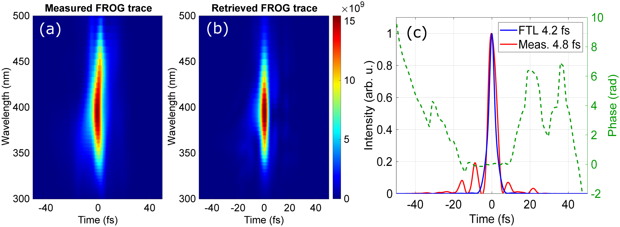
Figure 3 (a), (b) The measured and reconstructed SD-FROG traces. The reconstructed temporal intensity and phase of the pulse are shown in (c) together with the temporal profile of the Fourier-transform limited pulse.
3.3. Pulse energy scaling
The method demonstrated in this work is based on SHG in a BBO crystal and SPM in its fused-silica substrate. Pulse energy scaling can be achieved directly by adjusting the beam size on the BBO while maintaining the laser fluence. In the experiment, the input pulse energy was varied and the position of the BBO crystal was adjusted to achieve a spectral width of approximately 65 nm. The pulse duration and energy of the compressed pulses were measured. The compressed pulses exhibit durations of approximately 5 fs, similar to those obtained with input pulses of 8.1 mJ (Figure 3). The pulse energy of the compressed beam is plotted as a function of the fundamental pulse energy in Figure 4(a), clearly indicating a power scaling of the pulse energy of the compressed beam with respect to the pulse energy of the fundamental pulse. With an input pulse energy of 16 mJ, a compressed pulse with a pulse duration of 5 fs and a pulse energy of 1.05 mJ was achieved. Figure 4(b) summarizes the pulse duration and energy of the intense sub-10 fs 400 nm pulses demonstrated in this work and previous experiments with pulse energy higher than 100 μJ[ Reference Cheng, Khan, Zhao, Zhao, Chini and Chang25, Reference Liu, Zhao, He, Huang, Teng and Wei30, Reference Kanai, Zhou, Sekikawa, Watanabe and Togashi42, Reference Zhou, Kanai, Yoshitomi, Sekikawa and Watanabe43, Reference Xiao, Fan, Wang, Zhang, Wu, Wang and Zhao47]. Our approach allows us to push the pulse duration of the 400 nm pulses into the sub-5 fs regime with a pulse energy at the millijoule level.
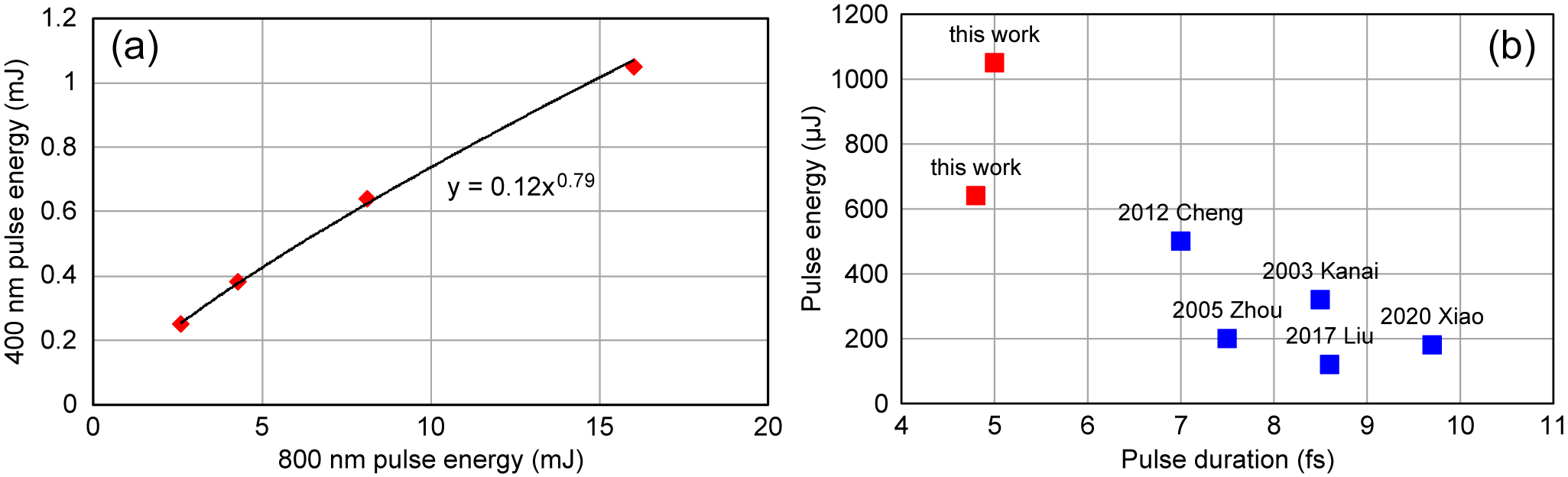
Figure 4 (a) The pulse energy of the compressed SHG pulse as a function of the fundamental pulse energy with a power function fitting. (b) A summary of pulse durations and energies for experimentally demonstrated intense sub-10 fs 400 nm pulses.
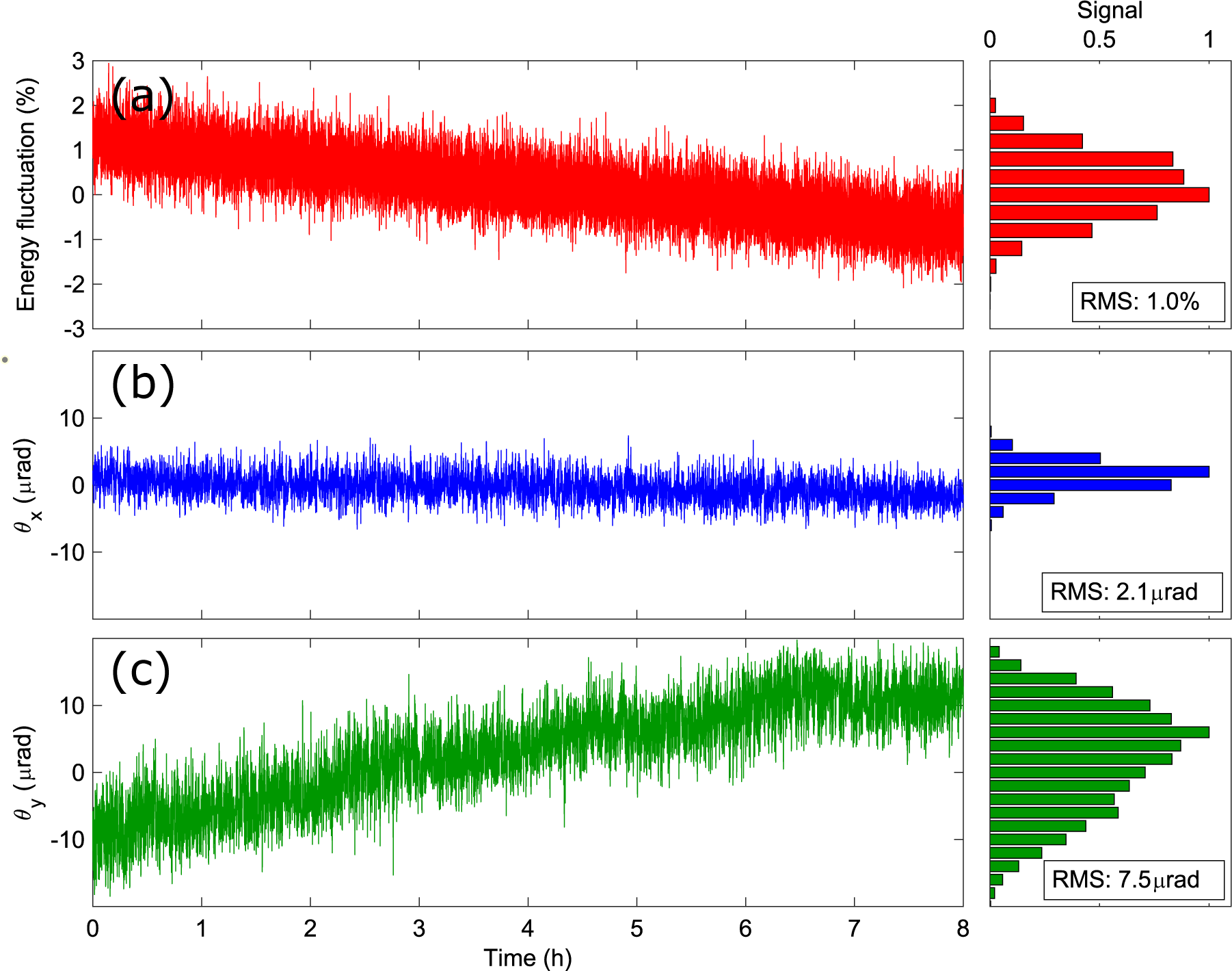
Figure 5 Single-shot measurements of pulse energy stability (a), and beam pointing along the horizontal ( ${\theta}_x$
) and vertical (
${\theta}_x$
) and vertical ( ${\theta}_y$
) directions (b), (c) over 8 hours for the compressed second harmonic beam. The histograms of the normalized stability distributions are plotted on the corresponding right-hand side panels.
${\theta}_y$
) directions (b), (c) over 8 hours for the compressed second harmonic beam. The histograms of the normalized stability distributions are plotted on the corresponding right-hand side panels.
3.4. Beam stability
The stability of the laser fluence at the interaction point is a key parameter to achieve reliable time-resolved experiments, which is determined by the pulse energy and beam-pointing stability. Therefore, it is essential to maintain stable pulse energy and beam pointing during experiments. To measure the stability, single-shot measurements of the pulse energy and beam pointing of the compressed second harmonic beam were performed at 5-s intervals over 8 hours. Regarding energy stability, the laser amplifier exhibited a root mean square (RMS) stability of approximately 0.15% over 24 hours for the fundamental beam. Figure 5(a) presents the measured pulse energy of the second harmonic beam over 8 hours, with an RMS stability of 1.0%, which is sufficient for most time-resolved applications. The beam-pointing stability was evaluated by measuring the beam profile of the collimated beam with a charge-coupled device (CCD) camera at the focus through an uncoated fused-silica lens with a focal length of 500 mm, as shown in Figure 1. The 2D spatial distribution exhibits a Gaussian-like shape. The beam positions along the horizontal and vertical directions are determined by fitting the measured beam profile to a 2D Gaussian function. The angular pointing deviations are calculated by dividing the changes in the peak position by the focal length of the lens. The measured angular pointing stabilities of the compressed second harmonic pulses were 2.1 and 7.5 μrad (rms) along the horizontal and vertical directions, respectively, as shown in Figures 5(b) and 5(c). We observed that the beam pointing along the vertical direction has a drift over 8 hours, which could be due to the beam-pointing drift of the input beam. Such drift also led to pulse energy dropping over 8 hours by about 1.5%. The beam-pointing drift can be compensated with a beam stabilization system before the SHG apparatus to improve the beam pointing and energy stability of the compressed second harmonic pulses.
4. Conclusion
In conclusion, we demonstrated the generation of millijoule-level sub-5 fs violet pulses from an all-solid free-space setup using a thin BBO crystal with a fused-silica substrate as the interaction medium. By harnessing the combined effects of SHG in the BBO crystal and SPM in the fused-silica substrate, we generated a broadband second harmonic beam with a bandwidth of 65 nm from a single optical component. Through the implementation of a chirped-mirror compressor, we compressed the broadened second harmonic pulses to a duration of 4.8 fs with a pulse energy of 0.64 mJ. Our method opens up new possibilities for generating intense violet and long wave UV pulses in the sub-5 fs regime, which holds great potential for a wide range of applications in nonlinear physics. For instance, it enables the generation of intense isolated attosecond pulses through high harmonic generation[ Reference Falcão-Filho, Lai, Hong, Gkortsas, Huang, Chen and Kärtner13, Reference Khan, Cheng, Möller, Zhao, Zhao, Chini, Paulus and Chang14]. Our all-solid setup offers several advantages, including its compact size, robustness and scalability in terms of pulse energy. These characteristics make it an ideal solution for various applications that require intense, ultrashort violet or long wave UV pulses, particularly in the field of ultrafast time-resolved experiments. Importantly, the methodology we developed in this work has broader applications beyond the scope of this specific demonstration. The spectral broadening and pulse compression techniques we implemented can be potentially extended to the generation of broadband and ultrashort UV and visible pulses through the utilization of harmonic generation using thin nonlinear media. This paves the way for advances in a variety of fields that rely on intense ultrashort pulse sources, such as nonlinear optics, ultrafast spectroscopy and attosecond science.


 Open access