


Introduction
Today it is impossible to imagine vehicles without radar sensors, especially since they are required by the European new car assessment program (Euro NCAP) to achieve high star rankings. Radar sensors demonstrate their advantages particularly under difficult environmental conditions, e.g. heavy rain or fog, where other sensors, such as optical or lidar systems, suffer from limited penetration depth and robustness. In the early days, now more than a decade ago, automotive radar started with comfort functions on motorways, as e.g. adaptive cruise control. Nowadays, radar also plays an important role in active safety solutions as e.g. emergency braking or assistance systems operating down to stop and go. In future it will become an important sensor for highly automated and autonomous driving [Reference Hasch, Topak, Schnabel, Zwick, Weigel and Waldschmidt1, Reference Hasch2].
Front-looking radars differ in their purpose and operation range. They are distinguished aslong-range radars (LRR), medium-range radars (MRR), and short-range radars (SRR). Especially LRRs require high-gain antenna systems, while modern MRRs typically apply digital beam forming and utilize an extended antenna array to achieve the required gain. Both, LRR and MRR systems operate at high frequencies and require significantly large apertures to detect at long range and a wide field of view.
In contrast, the ongoing integration brought up tiny antennas, either as antenna-in-package [Reference Tong, Fischer, Stelzer and Maurer3, Reference Fischer, Tong, Hamidipour, Maurer and Stelzer4] or even as antenna-on-chip solution [Reference Ng and Kissinger5] which limited aperture size and consequently gain. A straightforward solution is the combination of small feed antennas with dielectric lenses, e.g. at Bosch's LRR [Reference Hasch, Topak, Schnabel, Zwick, Weigel and Waldschmidt1, 6]. Compared to similar sized patch arrays the lens antenna circumvents feed losses occurring in a large network. However, the thickness and weight of such lenses imply a design drawback and expensive fabrication as e.g. mechanical milling, extrusion or injection molding.
Recent works [Reference Al-Joumayly and Behdad7–Reference Foo9] suggest the application of metamaterial lenses based on their promising advantages over conventional dielectric ones, which are low profile, light weight, simple fabrication, and low losses. These are important w.r.t. mass market production for automotive applications. Phase shifting metasurfaces can be built out of standard PCB material through etching and lamination [Reference Kohlberger, Hueber, Wagner and Stelzer10].
To show the applicability of thin metamaterial lenses, a four-channel monostatic LRR and an eight receive channel MRR, inspired by the FCC reports [6] and [11], were built. Both sensors operate around 77 GHz and were equipped with an appropriate thin lens. At the LRR, the spatial separation of the feeding patch antennas together with the focal length of the lens defines the resulting field of view. The MRR uses digital beamforming in azimuth direction, focussing the beam only in elevation direction via a cylindrical metamaterial lens.
This paper is an extension to the work presented at the European Microwave Conference 2021, published in [Reference Kohlberger, Huttner and Stelzer12].
Radar systems
Monostatic LRR
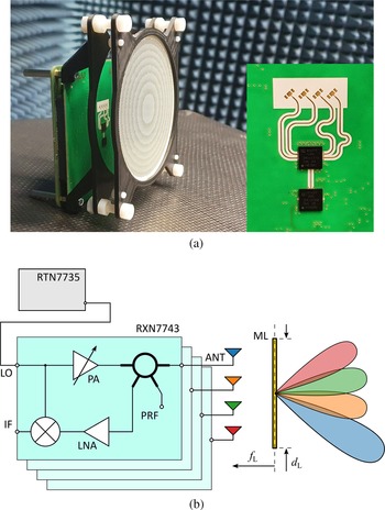
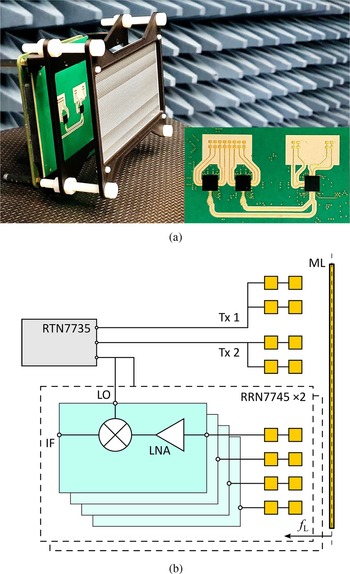
The LRR frontend features four transceiver channels based on the Infineon MMIC RXN7743, which is supplied by the LO signal from the transmitter Infineon RTN7735. The downconverted IF signal is sampled by the Texas Instruments AFE5801. All units, including the clock, were controlled by the Radar Companion Chip (Infineon RCC1010).
Figure 1 depicts the radar and the operation principle of the transceivers connected to the antennas in combination with the lens. In the transceiver, the LO signal is amplified by a power amplifier and passed through a hybrid-ring coupler to one of the four patch antennas. Here, the signal is emitted toward the lens, which further collimates the radiation. Depending on the radial offset between antenna and lens center, the originating high gain beam is directed off the symmetric axis. The received RF signal from reflections at a target is amplified by a low noise amplifier and down-converted at a mixer. In combination with the frequency modulation pattern, the resulting IF signal contains information about the target distance and its relative velocity to the radar sensor. A commercially available baseband (Radarbook 2) serves as an interface between radar frontend and PC.
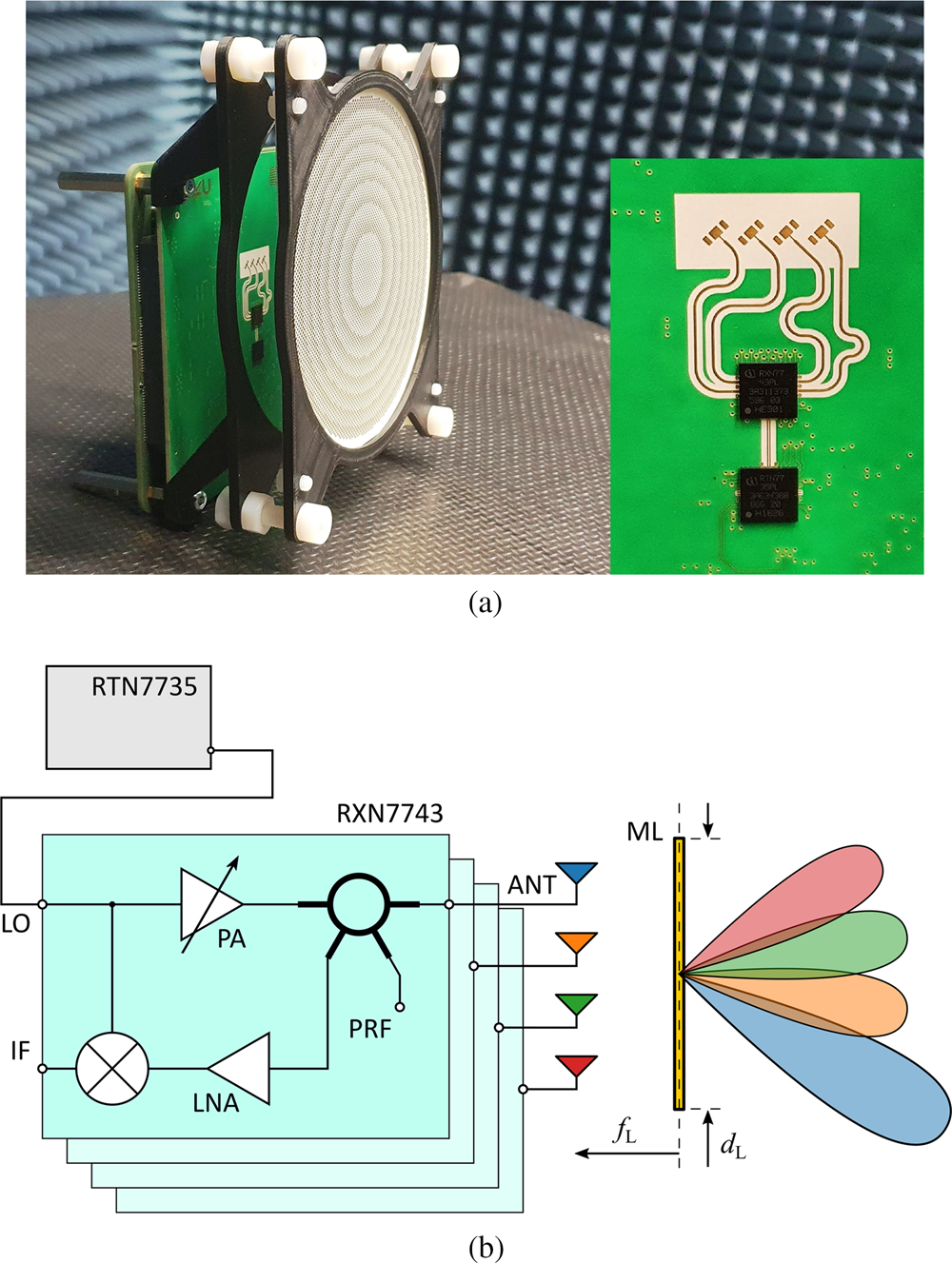
Fig. 1. Image (a) and schematic (b) of 77 GHz monostatic FMCW frontend with concentric metamaterial lens. Four antennas, connected to the transceiver, are located at the focal plane of the lens. The lateral offset of the single antennas results in a defined radiation direction.
Bistatic MRR
In contrast to the LRR, the transmit and receive channels are separated at the MRR. An image of the created radar frontend and a corresponding function schematic are shown in Fig. 2. Here, one can see that two differential channels of the RTN7735 are used as transmitters, whereas the third channel serves as LO for the two receiver chips RRN7745.
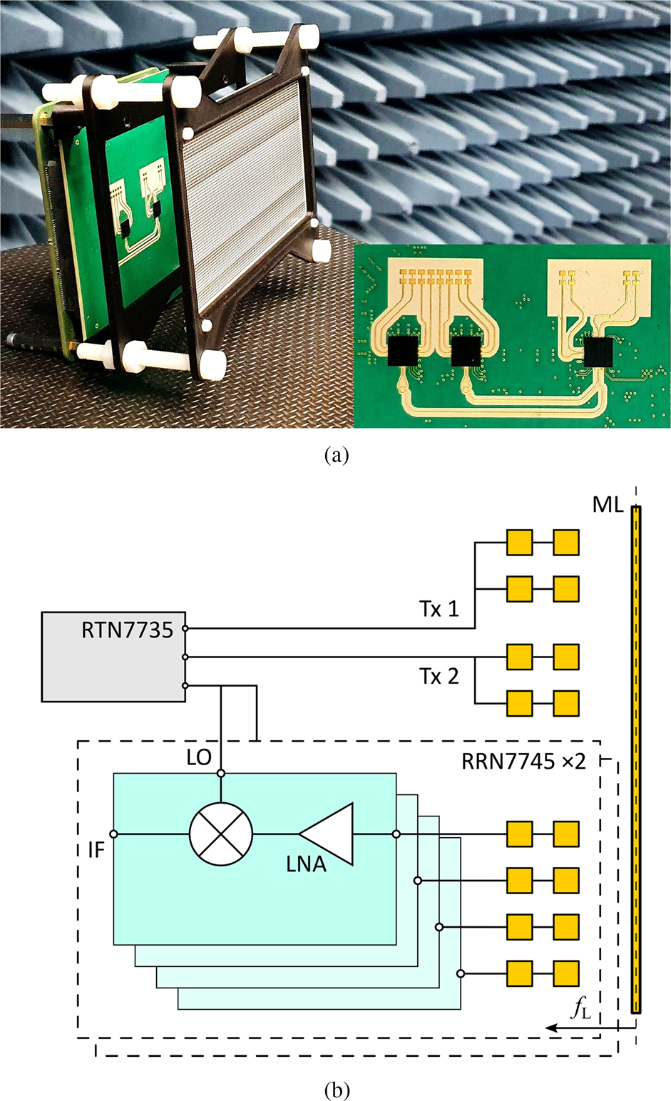
Fig. 2. Image (a) and schematic (b) of 77-GHz bistatic frontend with cylindrical lens. The radar transmits power via two differentially fed antennas and receives through eight double-patch antennas.
As above, the received RF signals are amplified at an LNA and get downconverted. The resulting IF signals are sampled at the A/D converter and digitally processed to detect the direction of a reflecting target. Obviously, phase manipulation across the receive antennas would obstruct radiation coherence and therewith disable beamforming. Hence, a cylindrical lens, which does not affect the transmission phase shift in the azimuth direction, is used at the MRR. In elevation, the metamaterial lens increases the gain of the series fed double-patch antennas.
Metamaterial lens
The metamaterial lens design followed the gradient optimization procedure described in [Reference Kohlberger, Hueber, Wagner and Stelzer10]. Here, discrete bandpass elements, exhibiting a variation of transmission phase shift over radius, enable constructive interference of an incident wave at the focus plane, as indicated in Fig. 3. To collimate radiation from a focal length $f_{ {L}}$ , arising phase differences Δφ at radial distances r are corrected by the metasurface with

The scattering behavior of single bandpass designs was found through continuous variation of grid widths and patch gaps on a six-layer PCB. As indicated in Fig. 1 in [Reference Kohlberger, Hueber, Wagner and Stelzer10], layers one, three, and five correspond to inductive grids which are defined by the widths w 1, w 3, and w 5. Layers two and four consist of patches, with gaps widths w 2 and w 4. Again, the dimensions w i were continuously optimized through full-wave simulations in HFSS applying Master–Slave boundaries and Floquet–Port excitation.
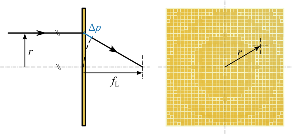
Fig. 3. Principle of metamaterial lens design. Incident rays at radii r exhibit different optical path lengths when interfering at the focal plane.
The ideal frequency responses of the bandpass elements follow a third-order Chebyshev filter with 0.1 dB ripple. A procedure, presented in [Reference Al-Joumayly and Behdad13], relates defined bandpasses to actual PCB designs, which serve then as starting point for the subsequent optimization. The PCB material was chosen to be RO4350B ($\varepsilon _ {{a}} = 3.66$ ) with prepreg consisting of RO4450F ($\varepsilon _ {{b}} = 3.35$
 ). Corresponding thicknesses read $t_ {{a}} = 100$
 μm and $t_ {{b}} = 80$
 μm. The metal layer periodicity was set to D = 1.05 mm. Six different filter designs were optimized with a bandwidth of 20 GHz at center frequencies $f_ {{C}}$
 from 65to 90 GHz.
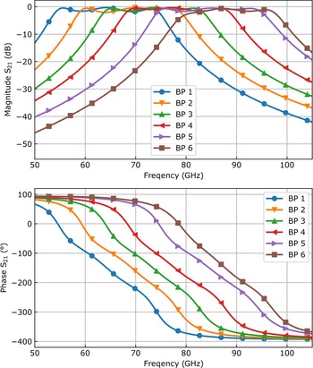
Figure 4 depicts the simulated frequency responses of the optimized bandpass designs. At 77 GHz, the phase variation over the six designs is >360$^\circ$ . However, the first and last bandpasses exhibit little transmission magnitude at the desired operation frequency, which corrupts the performance of a lens. To find more bandpass designs, showing an overall satisfactory phase shift variation at maximized transmission, the grid and patch array parameters were interpolated.

Fig. 4. Magnitude and phase of S 21 of the six simulation optimized filter designs (BP 1 to BP 6). The pass bands of the frequency responses around 77 GHz cover the desired phase variation of 360°.
The roughly linear relation between the structure parameters w i and transmission phase shift is shown in Fig. 5. Here one sees significant offset of some designs to the fit, which arises from the ambiguity of the optimization solutions. This means that different combinations of grid and patch widths can result in comparable frequency responses. Hence, to further improve the interpolation procedure, the six parameter sets (BP 1 to BP 6) were additionally weighted if desired. The 13 resulting design sets, presented in Table 1 in [Reference Kohlberger, Huttner and Stelzer12], exhibited sufficiently distributed phase shift at acceptable transmission. Additionally, none of the structure parameters exceed 0.95 mm nor fell below 0.1 mm, implying a minimum track width or gap clearance of at least 100 μm and therefore good manufacturability.

Fig. 5. Interpolated design parameters w i over transmission phase shift at 77 GHz. The marked grid widths and patch gaps at a certain phase shift correspond to the bandpass designs shown in Fig. 4. The parameters are related to BP 1 to BP 6 respectively from left to right.
To determine the frequency responses of the actual created metamaterial bandpasses, PCB samples with single multilayer design structures were fabricated and measured. Thereby, potential deviations between simulated and measured bandpass behavior, originating from fabrication uncertainties, could be discovered. Especially, the thickness of the single PCB substrate layers has strong impact on the final frequency responses and is usually difficult to control.
For the finally fabricated metamaterial lenses, the bandpass designs of Table 1 in [Reference Kohlberger, Huttner and Stelzer12] were arranged as suggested in Fig. 3 and Eqn (1). In total, three sets of thin lenses were fabricated, where the first one helped to estimate the performance of the collimating structures. These reference lenses exhibited a diameter of $d_ {{L}} = 100$ mm and focal lengths from 45 to 75 mm. The second set of lenses was created for the LRR and consisted of a mix of focal lengths $f_ {{L}} = 30$
 , 45, and 60 mm with diameters d LRR = 60 and 100 mm. Here, the grids and patches are tilted by 45$^\circ$
 to match the polarization of the four antennas of the monostatic frontend. Finally, three rectangular cylindrical lenses with focal lengths from again $f_ {{L}} = 30$
 to 60 mm and a size of 120 × 60 mm2 were fabricated for the MRR. These do not affect the transmission phase shift along the large side of the metasurface to preserve the beamforming capability of the bistatic radar. Therefore, the focussing diameter of the MRR lens corresponds to the broad side of the metasurface, namely d MRR = 60 mm.
Measurement and verification
Single bandpass structures and lenses
The verification of single bandpass structures was firstly presented in [Reference Kohlberger, Huttner and Stelzer12]. As described, the frequency responses of the single design samples were verified on a quasi optical bench (see [Reference Schultz14]) with the network analyzer ZVT20 from Rohde & Schwarz and W-band frequency extenders plus horn antennas. The measurement setup and corresponding results are depicted in Fig. 6, where the resulting S-parameters of three samples are compared to corresponding simulations. One sees that the frequency responses of the fabricated structures were shifted by approximately 2 GHz to lower frequencies, which implied limited transmission magnitude at bandpass designs exhibiting ${\rm arg}( {{S}}_{21}) < -250^\circ$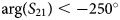 . Moreover, there was an offset between simulated and measured phases, which should not affect wave focussing, though.
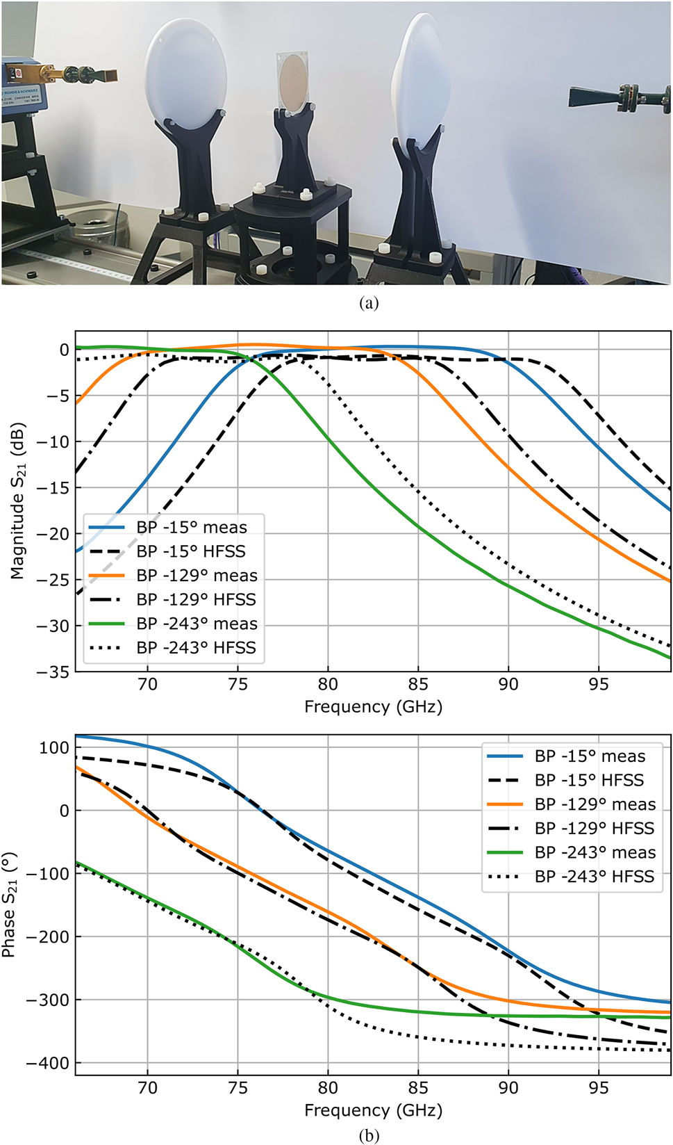
Fig. 6. (a) Image of quasi optical bench setup with horn antennas, dielectric lenses, and bandpass sample in the center. (b) Measured transmission magnitude and phase of three interpolated metamaterial bandpass examples compared to full-wave simulations. The measurement results were time gated to suppress ripples from mismatches within the setup. (b) Mid range radar.
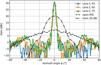
To verify the function of the lenses, the transmitted power of a 20 dBi W-band Flann horn antenna, an open-ended WR12 waveguide, and the waveguide–lens combinations were measured in azimuth angle-dependent direction. The distance between the open-ended waveguide and the lenses was equal to the corresponding focal length. All transmitters were fed by a signal generator connected to a 6×-frequency multiplier. In a distance of 2.8 m another W-band horn antenna received the incident waves, which were down-converted and provided to a spectrum analyzer.
Figure 7 depicts the measured beam patterns, where the power levels of the different gain curves were adjusted to 20 dBi of the horn antenna. One can see that the three lenses focus well, resulting in maximum gains between 29.8 and 30.9 dBi. The gain variation came from the different amount of collected energy at distinct focal lengths (see leaking power at large angles ±φ). As the lenses need to operate under frequency modulation of the radars, frequency-dependent gain measurements were performed. A variation of the frequency multiplier power levels was eliminated by reference measurements with the horn antenna. In Fig. 8, one can see that the lenses operate best at around 75 GHz, which is caused by the bandpass shift shown in Fig. 6b.

Fig. 7. Beam pattern of reference horn (dash-dotted), open waveguide (dashed), and waveguide–lens combination.
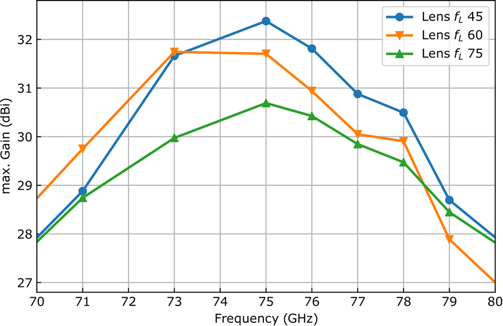
Fig. 8. Maximum gain of different waveguide–lens combinations plotted over frequency.
Lenses on radar systems
Finally, the radar frontends were tested with the different fabricated lenses. Thereby, a turntable rotated the radar systems, which were located 3 m apart from a 10 dBsm corner cube reflector. The frequency was modulated in the form of a sawtooth chirp from 76 to 78 GHz over 256 μs at around 1 dBm transmission power.
At the LRR measurements, only a single channel transmitted, while the received power was read at all four antennas. Figure 9 depicts the normalized receive power of the monostatic radar frontend behind two different metamaterial lenses, where the dynamic of all four antennas was larger than 30 dB. The black curves in Fig. 9a represent the LRR system with dielectric lens shown in [Reference Hasch, Topak, Schnabel, Zwick, Weigel and Waldschmidt1], which exhibits significantly larger side lobes than the metasurface solution. As expected, the angular lobe separation and the beam width depend on the focal length of the lens used. The measured dynamic of all different radar–lens combinations lies between 25 and 35 dB and is limited by the side lobe levels, which originate from off-center excitation. These side lobes, as well as the maximum receive power, increase with the lens diameter and off-focus excitation.
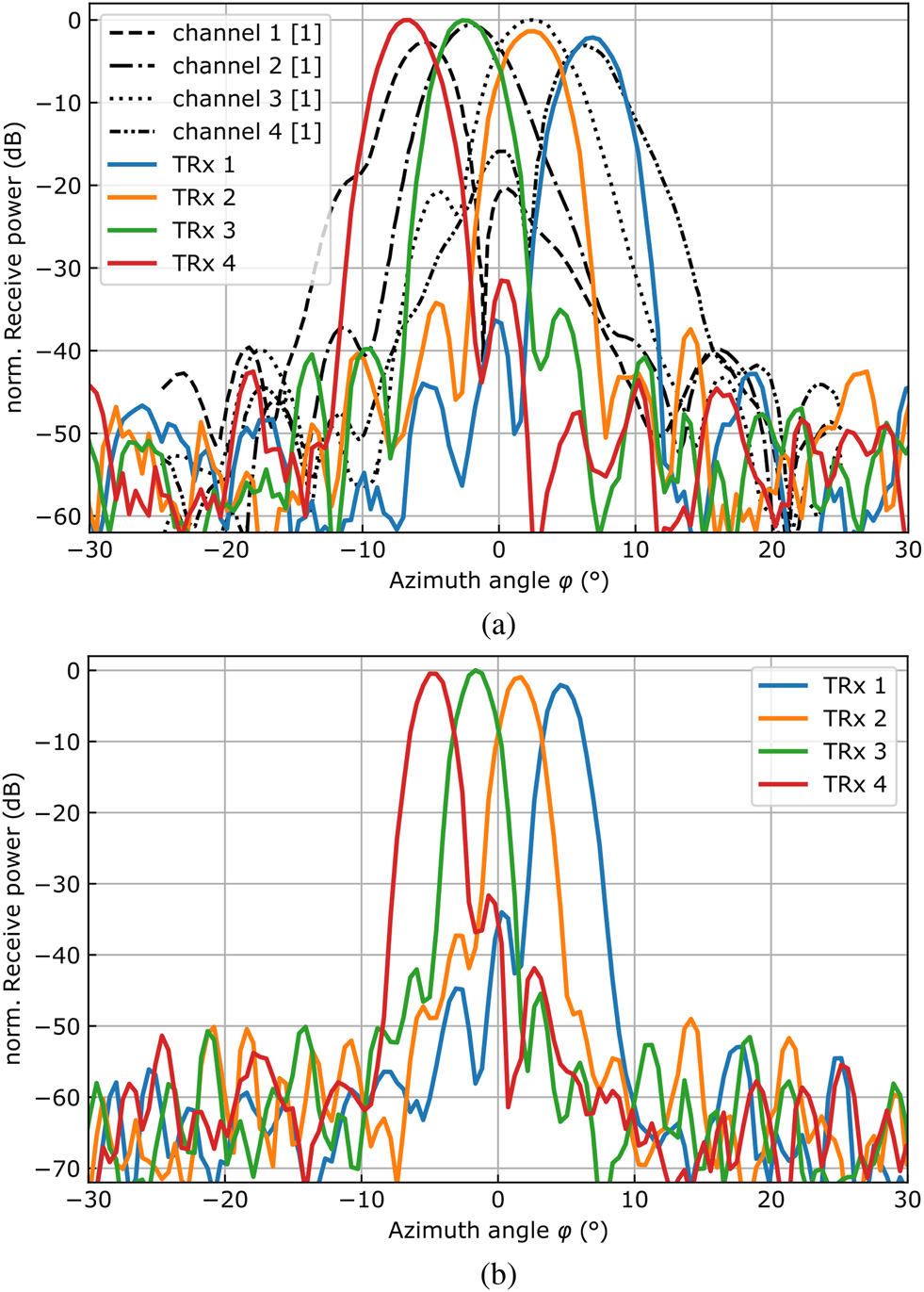
Fig. 9. Two-way beam patterns of the four-channel LRR frontend with two different lenses. A shorter focal length $f_ {{L}}$ increases the angle separation of the beams, whereas a larger lens diameter $d_ {{L}}$
 leads to narrower beams with higher maximum power. (a) $f_ {{L}} = 45$
 mm, d LLR = 60 mm, (b) $f_ {{L}} = 60$
 mm, d LLR = 100 mm.
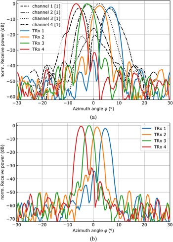
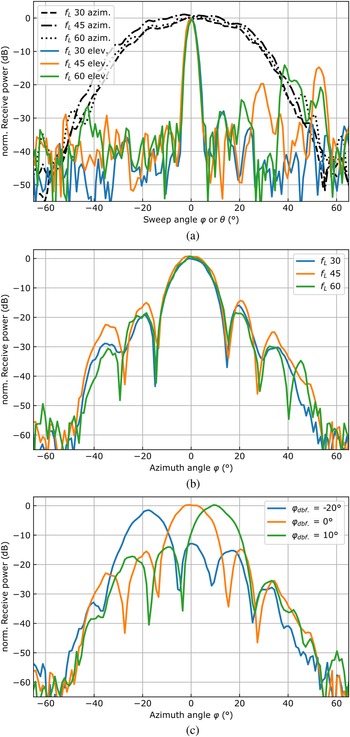
The bistatic MRR operated only with a single transmit channel (Tx 2) close to the center of the frontend, whereas all eight receive signals were read and processed. The resulting two-way beam patterns at a single channel (Rx 4) for azimuth and elevation are shown in Fig. 10a. Here, one sees the effect of the cylindrical lens on the MRR system gain. As expected, the half-power beam width in elevation is similar to those of the LRR TRx channels with d LRR = 60 mm lens. Moreover, there are increasing side lobes at the left side of the pattern, which come from focussed radiation onto the transmission lines of the frontend. Combining the received signals coherently results in the beam patterns in Fig. 10b, which are roughly equal for all three focal lengths. It needs to be mentioned that the MRR has to be calibrated after changing the metamaterial lens and adjusting its distance to the antennas accordingly. By applying phase factors to the complex receive signals, digital beam forming allows to sweep the receiver lobe over the azimuth angle. Resulting beam patterns at different target angles are depicted in Fig. 10c.

Fig. 10. Two-way beam patterns of the bistatic MRR frontend. (a) Azimuth and elevation angle-dependent receive power at channel 4 (from right to left) with three different lenses. (b) Coherently added receive power from the single receive channels with three different lenses. (c) Lobe separation through digital beamforming with the $f_ {{L}} = 45$ mm lens.
Conclusion
The presented work shows a successful implementation of thin metamaterial lenses in an automotive-inspired LRR and MRR operating at 77 GHz. An efficient metasurface design method, verification of the design frequency responses, and straight forward fabrication suggest the application of such lenses also in other areas, as communication and sensing. Remarkable radar beam patterns at the LRR inspire for applications beyond the automotive sector. The bright advantage of universal design freedom at thin metamaterial lenses is shown in the form of a cylindrical lens which was applied to an MRR utilizing digital beam forming.
Acknowledgements
The authors thank Dipl. Ing. Andreas Haderer for valuable support at operating the radar frontend and initializing the base-band. This work has been jointly supported by Infineon Technologies Linz and by Silicon Austria Labs (SAL), owned by the Republic of Austria, the Styrian Business Promotion Agency (SFG), the federal state of Carinthia, the Upper Austrian Research (UAR), and the Austrian Association for the Electric and Electronics Industry (FEEI).
Conflict of interest
None.
 Christoph Kohlberger (Student Member, IEEE) was born in Freistadt, Austria, in 1991. He obtained Dipl.Ing. (M.Sc.) in technical physics in 2018 from Johannes Kepler University Linz, Linz, Austria. Here, he is pursuing his Ph.D. in electronics and information technology at the Institute for Communications Engineering and RF Systems. In 2018, he joined Silicon Austria Labs GmbH (SAL), where he worked on a cooperative project as a scientist in the Millimeter Wave Technologies group. Currently, he is a radar algorithm engineer in the Flight Physics group at Joby Austria GmbH in Linz. His research interests include optics, electromagnetics, RF metasurfaces, their modeling, and related applications as well as novel concepts for radar systems.
 Richard Huttner was born in Steyr, Austria, in 1992. He finished his A-levels at HTL Steyr, Austria, with focus on electronics and technical informatics in 2012. Since then, he works as a technician at the Institute for Communications Engineering and RF-Systems at Johannes Kepler University Linz, Austria, where he gained expertise on RF measurements and PCB design. He contributes to various academic and industrial research projects through his continuous support.
 Christoph Wagner (Member, IEEE) was born in Zwettl, Austria, in 1980. He obtainedDipl.Ing. (M.Sc.) in mechatronics and Dr.Techn. (Ph.D.) in mechatronics from Johannes Kepler University Linz, Linz, Austria, in 2006 and 2010, respectively. In 2006, he joined Danube Integrated Circuit Engineering (DICE), today called Infineon Technologies Linz, Linz. In 2007, he became a member of the Christian Doppler Laboratory for Integrated Radar Sensors, Linz. Since 2010, he has been with Infineon, where he is currently responsible for the development of 77 GHz integrated radar transceivers. He has authored or coauthored more than 30 journal articles and conference papers. His research interests include circuit and system design for millimeter-wave and microwave radar sensors, with emphasis on digitally intensive techniques for RF imperfection mitigation.
 Andreas Stelzer (Member, IEEE) (MâĂŹ00) obtained Diploma Engineer in electrical engineering from the Technical University of Vienna, Vienna, Austria, in 1994, and Dr. techn. (Ph.D.) in mechatronics (with honors sub auspiciis praesidentis rei publicae) from the Johannes Kepler University (JKU) Linz, Austria, in 2000. In 2003, he became an associate professor with the Institute for Communications Engineering and RF Systems, Johannes Kepler University Linz. Since 2008, he has been a key researcher for the Austrian Center of Competence in Mechatronics (ACCM), where he is responsible for numerous industrial projects. In 2007 he was granted a Christian Doppler Research Laboratory for Integrated Radar Sensors and since 2011 he is a full professor at the Johannes Kepler University Linz, heading the Department for RF-Systems.


 Open access