


1. Introduction
Stand up (SU) and sit down (SD) movements are essential parts of daily human activity, and vital for independence in persons with disability, which caused by nervous disorder, muscle damage, and other diseases [Reference Frykberg and Häger1]. SU is destabilizing in nature, as the body rapidly changes from a stable seated position to a position with a relatively small base of support and a higher center of mass, but the SD is the inverse of above process. The importance of SU and SD is particularly evident when the ability deteriorates and manifests itself; it decreases the mobility-related quality of life and increases the risk of falls in the elderly as well as in persons with disabilities.
In recent years, the application of wearable exoskeleton has become more prominent as to provide alternative solutions for care-needing older adults and disabled individuals support in their daily movements, such as SU, SD, ascending and descending staircases [Reference Norhafizan, Ghazilla, Kasi, Taha and Hamid2, Reference Viteckova, Kutilek, de Boisboissel, Krupicka, Galajdova, Kauler, Lhotska and Szabo3]. Wu et al. [Reference Wu, Zhang, Liao, Wang, Wu and Wu4] present a self-adaptive control strategy used on lower limb exoskeleton to help paraplegic patients to SU and SD, but its speeds are slower than joints of normal people. Chen et al. [Reference Chen, Zhong, Zhao, Ma, Guan, Li, Liang, Cheng, Qin and Law5, Reference Chen, Zhong, Ma, Guan, Qin, Chan, Law, Qin and Liao6] present a wearable exoskeleton suit (CUHK-EXO) to help paralyzed patients regain the ability to walk, SU and SD. Safety tests for long-term wearing of CUHK-EXO will also be conducted in the future, including any adverse effect in the hip, groin, penis, back, wrist, glutei, and scapula of the wearers. Jatsun et al. [Reference Jatsun, Savin, Yatsun and Gaponov7] study on a lower limb exoskeleton performing standing up motion from a chair, and present a modified Jacobian transpose controller which allowed to implement the proposed combined control strategy. Karen Junius et al. [Reference Junius, Brackx, Grosu, Cuypers, Geeroms, Moltedo, Vanderborght and Lefeber8] present an exoskeleton to assist the wearer during sit to stand activities, which driven by compliant mechanically adjustable compliance and controllable equilibrium position actuator. In addition, the exoskeleton consists of six active flexion/extension joints. Kamali et al. [Reference Kamali, Akbari and Akbarzadeh9] present a novel control approach for a knee exoskeleton to assist individuals with lower extremity weakness during sit-to-stand motion. It consists of a trajectory generator and an impedance controller; the misalignment errors reduce the effectiveness of the exoskeleton controller.
Above exoskeletons use many electric motors to help patients to SU or SD; it consumes large amounts of electric energy, and not able to work for long hours. Moreover, the complexity of control system of exoskeletons is added, because of the influence of controllers, sensor and electric source, and so on.
The power sources of the unpowered lower limb exoskeletons are gait energy, which includes the kinetic energy and gravitational potential energy of body. The energy storage element (spring, elastic strap, torsional spring, pneumatic muscle, etc.) is used to store gait energy, and the clutches change the work pattern of energy storage element at the right time. One of the earliest records of an unpowered exoskeleton to assist human walking was found in a patent; it has two bowsprings that spanned the length of the leg [Reference Yangn10]. Collins et al. [Reference Collins, Wiggin and Sawicki11] designed a lightweight exoskeleton that provides some of the functions of the calf muscles and tendons during walking; it reduces the metabolic cost of walking about 7.2 $\pm$
2.6% for healthy human users under natural gait conditions. Cherelle et al. [Reference Cherelle, Grosu, Matthys, Vanderborght, Lefeber and Syst12] developed a minimally actuated transtibial prosthesis; it consists of three bodies pivoting around a common axis (the ankle) and uses a two-spring system to harvest energy throughout the stance phase, and the elastic potential energy of springs is released at toe-off. Hirai et al. [Reference Hirai, Ozawa, Goto, Fujigaya, Yamasaki, Hatanaka and Kawamura13] developed a passive ankle-foot orthosis; it uses a pneumatic element to provide a restraining force that can lock the ankle in a neutral position. Walsh et al. [Reference Walsh, Endo and Herr14] presented a quasi-passive exoskeletal for load carrying that achieves an improved walking metabolic performance as compared to a standard loaded backpack; it transfers on average 80% of the load to the ground during the single support phase of walking. Scott and Marc [Reference Pardoel and Doumit15] presented a passive ankle exoskeleton; it used a pneumatic artificial muscle (PAM) as a non-linear elastic element to store and release energy during walking. Dijk et al. [Reference Van Dijk, Van der Kooij and Hekman16] developed a passive lower limb exoskeleton that used artifiial tendons to minimize the joint work during walking; it reduces human energy expenditure obviously. Lee et al. [Reference Lee, Kim and Park17] presented an entirely soft and passive knee extension assist wear (X-tights); it is developed by an optimized tendon routing method using elastic bands inspired by the anatomical design of human knee extensor for effective force transfer across the lower body. Panizzolo et al. [Reference Panizzolo, Bolgiani, Di Liddo, Annese and Marcolin18] proposed a passive wearable assistive device (Exoband); it applies a torque to the hip flexion, thus reducing the net metabolic power of wearers. Rome et al. [Reference Rome, Flynn and Yoo19] found that use of rubber bands in parallel with the hip joint can reduce the metabolic costs of carrying loads during walking. Haufe et al. [Reference Haufe, Wolf, Riener and Grimmer20] find that a spring attached anteriorly across the hip appears to store and return proportions of the elastic energy. As energy is returned, the spring assists hip flexion, while muscle activity related to ankle plantarflexion around push-off increases. Zhang [Reference Zhang21] presented a passive lower limb exoskeleton suit; it utilizes the passive dynamics of level walking to convert mechanical energy otherwise dissipated during the gait cycle into elastic potential energy, and the mechanical work potential was increased when the energy was returned to assist the leg during a different period of the gait cycle. Rezvan et al. [Reference Nasiri, Ahmadi, Ahmadabadi and Syst22] designed an unpowered exoskeleton with a bent-leaf-spring (BLS); it reduces the metabolic cost of running by 8.0
$\pm$
2.6% for healthy human users under natural gait conditions. Cherelle et al. [Reference Cherelle, Grosu, Matthys, Vanderborght, Lefeber and Syst12] developed a minimally actuated transtibial prosthesis; it consists of three bodies pivoting around a common axis (the ankle) and uses a two-spring system to harvest energy throughout the stance phase, and the elastic potential energy of springs is released at toe-off. Hirai et al. [Reference Hirai, Ozawa, Goto, Fujigaya, Yamasaki, Hatanaka and Kawamura13] developed a passive ankle-foot orthosis; it uses a pneumatic element to provide a restraining force that can lock the ankle in a neutral position. Walsh et al. [Reference Walsh, Endo and Herr14] presented a quasi-passive exoskeletal for load carrying that achieves an improved walking metabolic performance as compared to a standard loaded backpack; it transfers on average 80% of the load to the ground during the single support phase of walking. Scott and Marc [Reference Pardoel and Doumit15] presented a passive ankle exoskeleton; it used a pneumatic artificial muscle (PAM) as a non-linear elastic element to store and release energy during walking. Dijk et al. [Reference Van Dijk, Van der Kooij and Hekman16] developed a passive lower limb exoskeleton that used artifiial tendons to minimize the joint work during walking; it reduces human energy expenditure obviously. Lee et al. [Reference Lee, Kim and Park17] presented an entirely soft and passive knee extension assist wear (X-tights); it is developed by an optimized tendon routing method using elastic bands inspired by the anatomical design of human knee extensor for effective force transfer across the lower body. Panizzolo et al. [Reference Panizzolo, Bolgiani, Di Liddo, Annese and Marcolin18] proposed a passive wearable assistive device (Exoband); it applies a torque to the hip flexion, thus reducing the net metabolic power of wearers. Rome et al. [Reference Rome, Flynn and Yoo19] found that use of rubber bands in parallel with the hip joint can reduce the metabolic costs of carrying loads during walking. Haufe et al. [Reference Haufe, Wolf, Riener and Grimmer20] find that a spring attached anteriorly across the hip appears to store and return proportions of the elastic energy. As energy is returned, the spring assists hip flexion, while muscle activity related to ankle plantarflexion around push-off increases. Zhang [Reference Zhang21] presented a passive lower limb exoskeleton suit; it utilizes the passive dynamics of level walking to convert mechanical energy otherwise dissipated during the gait cycle into elastic potential energy, and the mechanical work potential was increased when the energy was returned to assist the leg during a different period of the gait cycle. Rezvan et al. [Reference Nasiri, Ahmadi, Ahmadabadi and Syst22] designed an unpowered exoskeleton with a bent-leaf-spring (BLS); it reduces the metabolic cost of running by 8.0 $\pm$
1.5% as compared with no-exoskeleton case. In addition, considering the exoskeleton mass in metabolic cost normalization, the average metabolic cost reduction is 10.2
$\pm$
1.5% as compared with no-exoskeleton case. In addition, considering the exoskeleton mass in metabolic cost normalization, the average metabolic cost reduction is 10.2 $\pm$
1.5%. Ronnapeet et al. [Reference Chaichaowarat, Kinugawa and Kosuge23] developed an exoskeleton prototype using a crossing four-bar mechanism as a knee joint with an embedded torsion spring. Its total mass is 1070 g, compared with 490 g for the original knee brace, and it decreases muscle activity of rectus femoris (RF). Matthew et al. [Reference Yandell, Tacca, Zelik and Syst24] presented a novel unpowered ankle exoskeleton that is low profile, lightweight, quiet, low cost to manufacture, and intrinsically adapts to different walking speeds. It does not restrict non-sagittal joint motion and blends the torque assistance of the prior exoskeleton with the form-factor benefits of clothing. Leclair et al. [Reference Leclair, Pardoel, Helal and Doumit25] presented a lightweight unpowered ankle exoskeleton with PAM. The PAM were installed on the shank upright component; it harvests energy through the stance phase and releases the accumulated energy at push-off. Copilusi et al. [Reference Copilusi, Ceccarelli and Carbone26] presented a low-cost exoskeleton with fairly simple construction, lightweight, easy to wear and to adapt to human legs. It used a cam-mechanism implementation at the ankle joint level using a low-cost biped mechanism. Ji et al. [Reference Guan, Ji, Wang and Huang27] developed a novel unpowered energy-stored exoskeleton (ES-EXO) for spinal cord injured patients. It provides specific walking assistance for SCI patients according to the parameters of energy-stored elements. The energy is stored by lumbar muscles contraction in stance phase and released in swing phase.
$\pm$
1.5%. Ronnapeet et al. [Reference Chaichaowarat, Kinugawa and Kosuge23] developed an exoskeleton prototype using a crossing four-bar mechanism as a knee joint with an embedded torsion spring. Its total mass is 1070 g, compared with 490 g for the original knee brace, and it decreases muscle activity of rectus femoris (RF). Matthew et al. [Reference Yandell, Tacca, Zelik and Syst24] presented a novel unpowered ankle exoskeleton that is low profile, lightweight, quiet, low cost to manufacture, and intrinsically adapts to different walking speeds. It does not restrict non-sagittal joint motion and blends the torque assistance of the prior exoskeleton with the form-factor benefits of clothing. Leclair et al. [Reference Leclair, Pardoel, Helal and Doumit25] presented a lightweight unpowered ankle exoskeleton with PAM. The PAM were installed on the shank upright component; it harvests energy through the stance phase and releases the accumulated energy at push-off. Copilusi et al. [Reference Copilusi, Ceccarelli and Carbone26] presented a low-cost exoskeleton with fairly simple construction, lightweight, easy to wear and to adapt to human legs. It used a cam-mechanism implementation at the ankle joint level using a low-cost biped mechanism. Ji et al. [Reference Guan, Ji, Wang and Huang27] developed a novel unpowered energy-stored exoskeleton (ES-EXO) for spinal cord injured patients. It provides specific walking assistance for SCI patients according to the parameters of energy-stored elements. The energy is stored by lumbar muscles contraction in stance phase and released in swing phase.
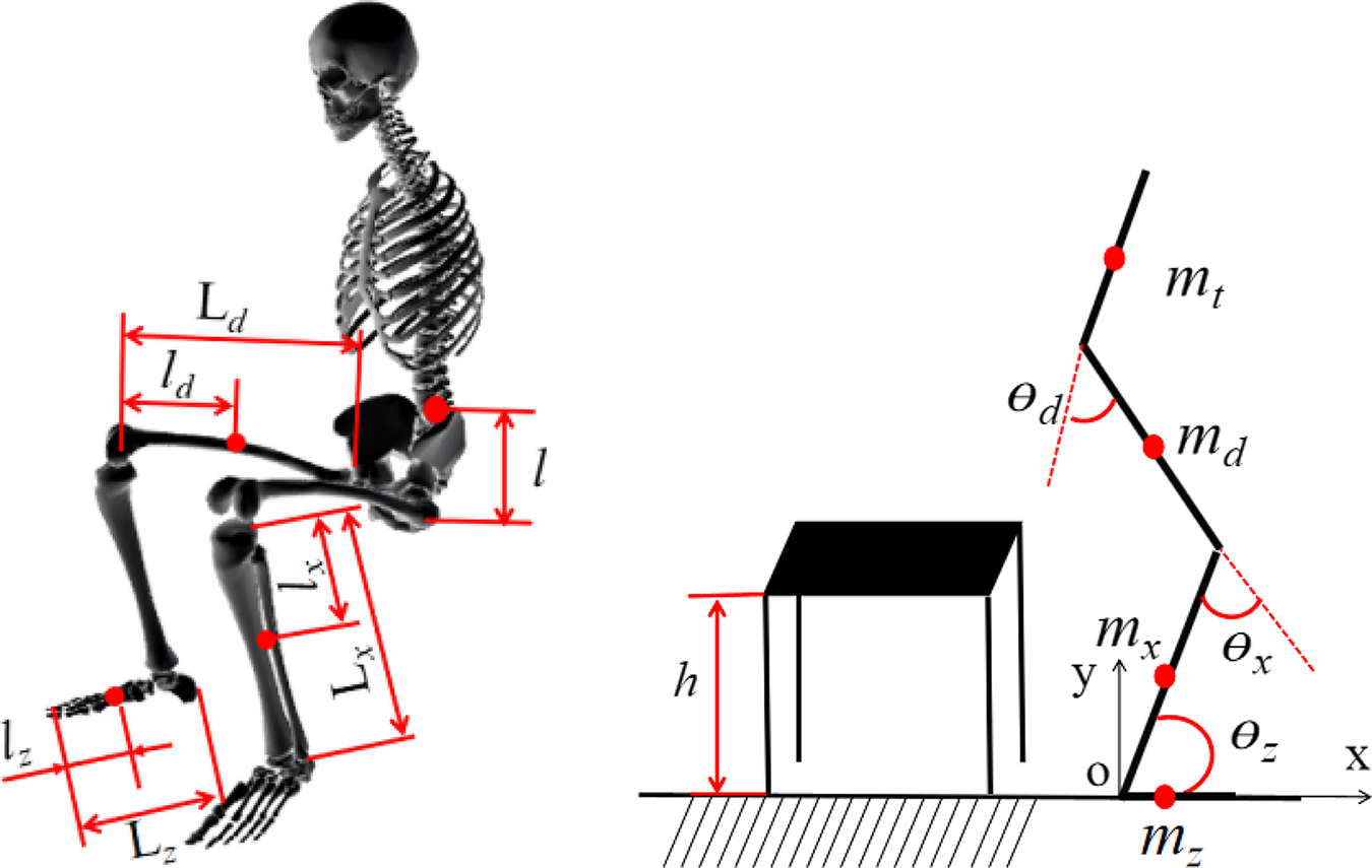
Figure 1. Sit down (SD) model of lower extremity.
The stiffness of elastic elements for those unpowered lower extremity exoskeletons is fixed, but the stiffness of muscle is variable in the different activities of the human body, so elastic elements are inconvenient for the utilization gait energy, which weaken the assist effect of exoskeleton. Besides, most previous studies have paid little attention to the metabolic cost of body during SD/SU, ascending/descending staircases, and so on; it is unfavorable for evaluation and application of exoskeletons. The utilization mechanism of gait energy is described in detail in this paper, and the design principles of elastic energy storage element are determined, which contain the work mode, location, and stiffness. Then, a novel, modular, light mass unpowered lower extremity exoskeleton is presented; the metabolic cost of body during SD/SU is analyzed, under the exoskeleton conditions. This exoskeleton helps patients with abnormal gait to convenient, low cost, and stable walking.
The paper’structure is arranged as follows. Firstly, the SD of human model is established by Lagrange method, and bionics structure design of unpowered lower extremity exoskeleton is proposed in Section 2. It consists of elastic energy storage elements, clutch devices, waistband, kneepad, shoes, and so on. The forces of muscles, stiffness of joints, and contribution degree of muscles involve in SU and SD are analyzed in Section 3. Then the exoskeleton-muscular system is analyzed by the Opensim software system, and the metabolic cost of relevant muscles of lower extremity is obtained in Section 4, under different stiffness of energy storage components. Lastly, Section 5 summarizes the full paper.
2. Materials and methods
2.1. Dynamics analysis of lower extremity during SD
Motion analysis is a well-established tool for the quantitative assessment of activity ability of body; it includes the kinematics and kinetics analysis of body and provides functional diagnosis, assessment for treatment planning, and monitoring of disease progress for the person. Using vector analysis method, the inverse and forward kinematics solution of body are solved, and the motion characteristics of lower extremity is analyzed by Lagrange method in this paper. Compared to other methods, the Lagrange method has many remarkable advantages such as simple calculation process, take no account of friction loss and interacting forces in system. The lower extremity is regard as multibody dynamic model which consist of trunk, hip, knee, ankle and foot, as shown in Fig. 1. The mass of trunk, thigh, shank, and foot is mt, md, mx, and mz; the length of thigh, shank, and foot is $ L_{d}, L_{x}, L_{z} $
; the distance between mass center and joints for trunk, thigh, shank, and foot is l,
$ L_{d}, L_{x}, L_{z} $
; the distance between mass center and joints for trunk, thigh, shank, and foot is l, $ l_{d}$
,
$ l_{d}$
, $ l_{x} $
,
$ l_{x} $
, $ l_{z} $
; the joint angle of hip, knee, and ankle is
$ l_{z} $
; the joint angle of hip, knee, and ankle is $\theta _{d}$
;
$\theta _{d}$
; $\theta _{x}$
;
$\theta _{x}$
; $\theta _{z}$
; respectively.
$\theta _{z}$
; respectively.
According to the SD model of lower extremity, the mass center coordinates of foot are
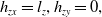 \begin{equation}h_{zx}=l_{z}, h_{zy}=0,\end{equation}
the mass center coordinates of shank are
 \begin{equation}h_{xx}=\left( L_{x}-l_{x}\right)\cos\theta _{z}; h_{xy}=\left( L_{x}-l_{x}\right)\sin\theta _{z}\end{equation}
the mass center coordinates of thigh are
 \begin{equation} \left\{\begin{aligned}h_{dx} & = & L_{x}\sin\theta _{z}- l_{d}\cos\left(180-\theta _{z}-\theta _{x}\right) \\h_{dy} & = & L_{x}\cos\theta _{z}+ l_{d}\sin\left(180-\theta _{z}-\theta _{x}\right) \\\end{aligned}\right.\end{equation}
the mass center coordinates of trunk are
 \begin{equation}\left\{\begin{aligned}h_{tx} & = & L_{x}\sin\theta _{z}- L_{d}\cos\left(180-\theta _{z}-\theta _{x}\right)+l\cos\left(\theta _{x}+\theta _{z}-\theta _{d}\right) \\h_{ty} & = & L_{x}\cos\theta _{z}+ L_{d}\sin\left(180-\theta _{z}-\theta _{x}\right)+l\sin\left(\theta _{x}+\theta _{z}-\theta _{d}\right) \\\end{aligned}\right.\end{equation}
The velocity of mass center of trunk, thigh, and shank is obtained by taking the derivative of Formulas (2), (3), and (4), respectively. Then the total kinetic energy of single leg is obtained.
 \begin{equation}\begin{aligned}T&=\frac{1}{2}m_{x}v_{x}^{2}+\frac{1}{2}J_{Cx}\dot{\theta} _{z}^{2}+\frac{1}{2}m_{d}v_{d}^{2}+\frac{1}{2}J_{Cd}\dot{\theta} _{x}^{2}+\frac{1}{2}m_{t}v_{t}^{2}+\frac{1}{2}J_{Ct}\dot{\theta} _{d}^{2} \\[3pt]&= \frac{1}{2}{m_{\rm{x}}}[({{\rm{L}}_{\rm{x}}}{\rm{ - }}{l_{\rm{x}}}){{\dot \theta }_z}]^2 + \frac{1}{2}{J_{C{\rm{x}}}}{{\dot \theta }_z}^2 \\[3pt]&+ \frac{1}{2}{m_d}[{{L_x}^2} + {{l_d}^2} + 2{L_x}{l_d}\sin ( {{\theta _z}} - \hat \theta ){{\dot \theta }_z}^2 + {{l_d}^2}{{\dot \theta }_x}^2] + \frac{1}{2}{J_{Cd}}{{\dot \theta }_x}^2 \\[3pt]&+ \frac{1}{2}{m_t}[{{L_x}^2} + {{L_d}^2} + {l^2} + 2{L_x}{L_d}\sin ( {{\theta _z}} - \hat \theta )]{{\dot \theta }_z}^2{{\dot \theta }_d}^2 \\[3pt]&- {m_t}[{L_x}l\sin ({\theta _z}+ \bar \theta ) + {L_d}l \cos (\hat \theta+ \bar \theta )]{{\dot \theta }_z}^2{{\dot \theta }_d}^2 \\[3pt]&+ \frac{1}{2}{m_t}[{{L_d}^2} + {l^2} - 2{L_d}l\cos (\hat \theta+ \bar \theta )]{{\dot \theta }_x}^2{l^2}{{\dot \theta }_d}^2 + \frac{1}{2}{J_{Ct}}{{\dot \theta }_d}^2\end{aligned}\end{equation}
where $ \hat{\theta}=180 - {\theta _z} - {\theta _x},\bar{\theta}= {\theta _x} + {\theta _z} - {\theta _d} $
The total potential energy of single leg is P
 \begin{equation}\begin{aligned}P&=m_{x}g\left( L_{x}-l_{x}\right)\sin\theta _{z}+m_{d}g\left(L_{x} \cos\theta _{z}+l_{d}\sin\left(180-\theta _{z}-\theta _{x}\right)\right)\\[3pt]&+m_{t}g\left( L_{x}\cos\theta _{z}+L_{d}\sin\left(180-\theta _{z}-\theta _{x}\right)+l\sin\left(\theta _{x}+\theta _{z}-\theta _{d}\right)\right) \end{aligned}\end{equation}
Lagrange equation is defined as the difference between kinetic energy (T) and potential energy (P), as Formulas (7) and (8):
 \begin{equation}L=T-P \end{equation}
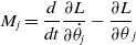 \begin{equation}M_{j}=\frac{d}{dt}\frac{\partial L}{\partial \dot{\theta} _{j}}-\frac{\partial L}{\partial \theta} _{j}\end{equation}
where $\theta _{j}$
,
$\theta _{j}$
, $\dot{\theta} _{j}$
are the generalized angle and generalized velocity of hip, knee, and ankle, respectively.
$\dot{\theta} _{j}$
are the generalized angle and generalized velocity of hip, knee, and ankle, respectively.
 \begin{equation}p_{i}=M_{i}\theta _{j},\end{equation}
The joint power of body is described as working ability of joints; according to Eq. (9), the joint powers of lower extremity are obtained, respectively.
The motion capture system (Vicon) with AMTI force plates is considered the gold standard for human movement analysis in the field of biomechanics. The Vicon system used consists of six high resolution cameras that collect the infrared light reflected by retro-reflective markers in our laboratory, two AMTI force plates with a sampling frequency of 1000 Hz, as shown in Fig. 2.
The motion capture procedure is as follows: (1) a subject that is about 1.80 m and 71.2 kg, the motion parameters of human as shown in Table I. (2) the view parameters of high-speed camera are adjusted in biomechanics laboratory, make sure that the body in visual range of cameras and the coordinate calibration of cameras is set. (3) the body model with 31 markers is established in Opensim musculoskeletal system (gait2354-simbody), and the markers are pasted on the subjects at appropriate locations. (4) the motion data of human are dynamic and static collected by Vicon system, and they are patched and corrected; the angles of joints of lower extremity were acquired, as shown in Fig. 3.
Table I. The motion parameters of human [Reference Anderson and Pandy29]
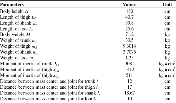
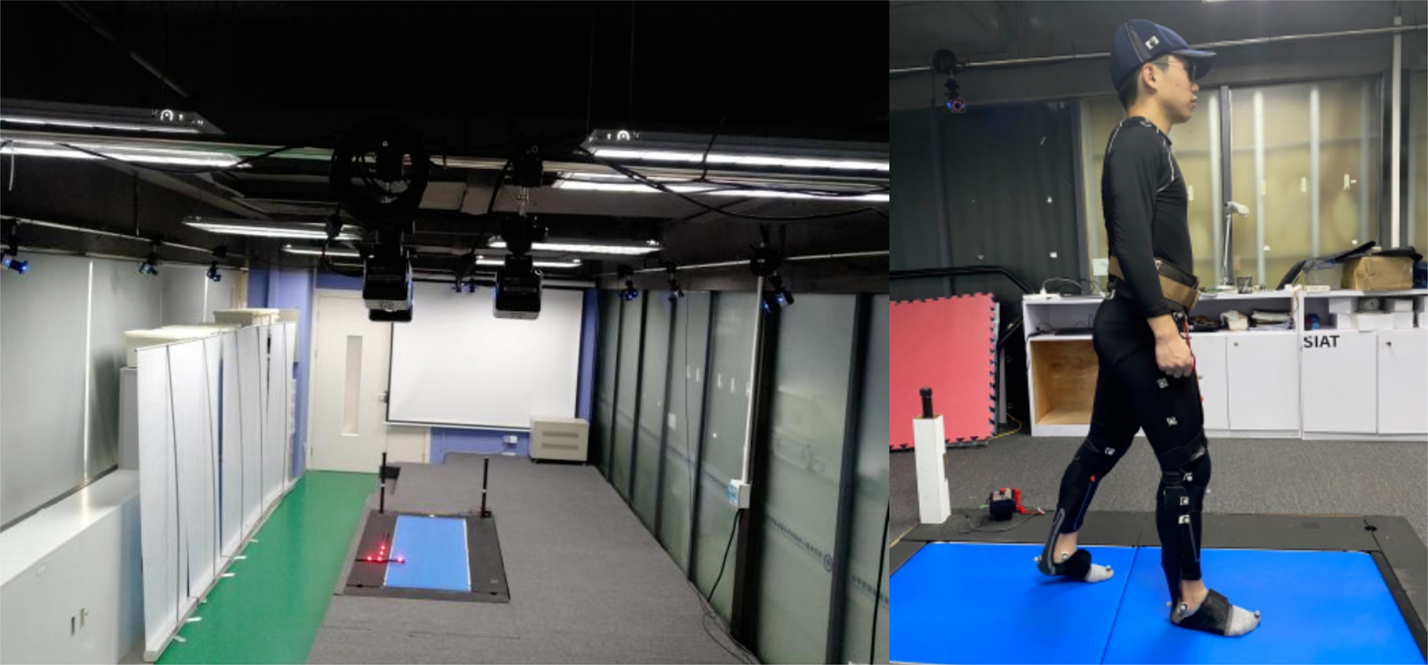
Figure 2. Vicon motion capture system.
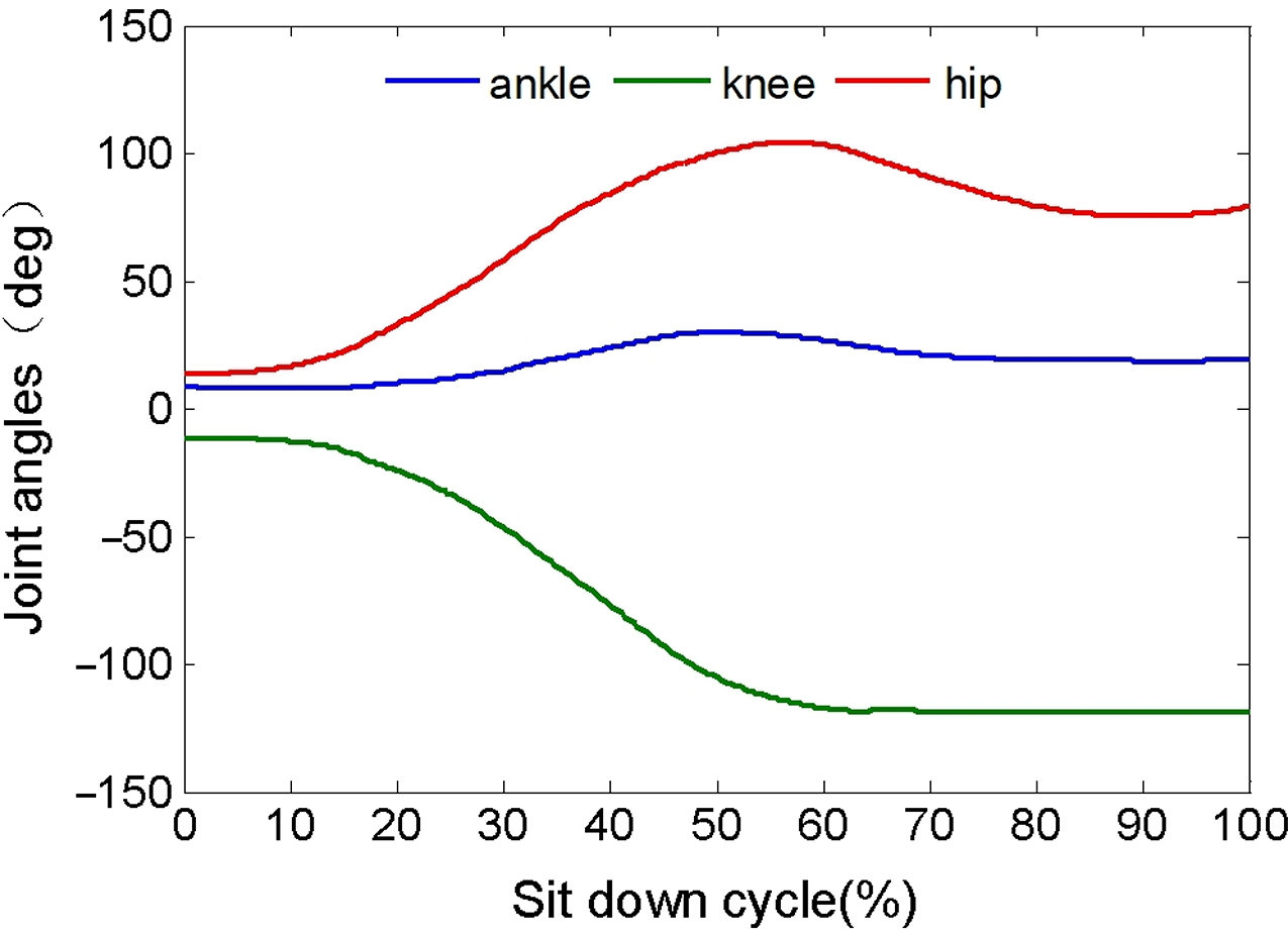
Figure 3. The angle of joints during SD.
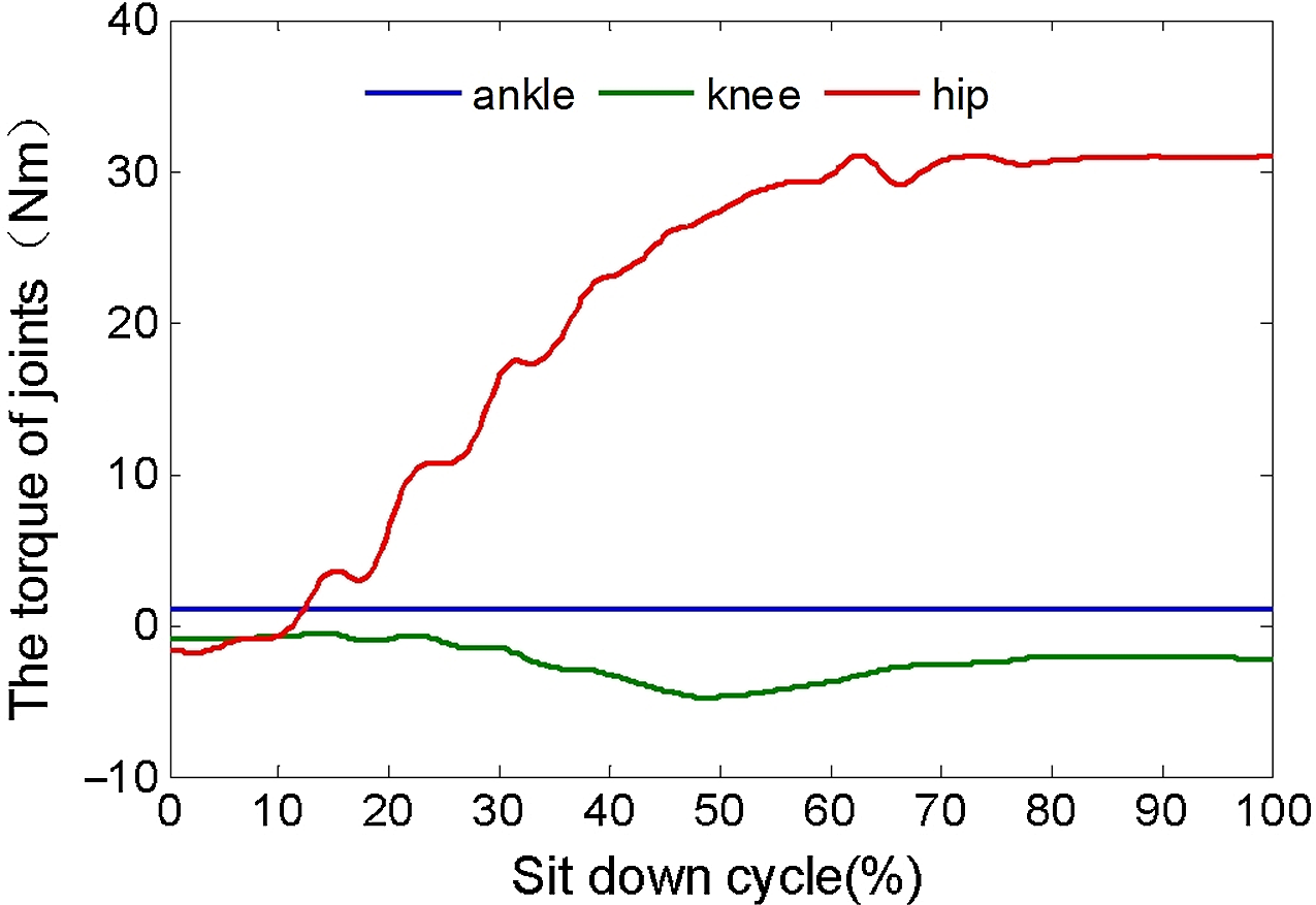
Figure 4. The torque of joints (left leg).
During the normal gait, the angles of joint of lower extremity have obvious periodicity, and the originality datum needs further processing because of the tremble of limbs and trunk. So the datum of markers was analyzed by Fourier transform algorithm, which has many remarkable advantages such as simple calculation process, high efficiency, fast speed, and high fidelity [Reference Krepelka, Hynstova, Pytel, Prez-Rodrguez, Roger and Drexler28]. The Fourier series equation can be described as follows:
 \begin{equation}f\left( t\right) =a_{0}+\sum_{k=1}^m\left( a_k\cos\theta\left( kwt\right)+ b_k\sin\theta\left( kwt\right) \right) \end{equation}
where $a _{0}$ $a _{k}$ $b _{k}$
is the uncertainty coefficient of Fourier function, respectively; t is the time constant, m is the Fourier series coefficients,
$b _{k}$
is the uncertainty coefficient of Fourier function, respectively; t is the time constant, m is the Fourier series coefficients, $ m \le \frac{n}{2}$
.The Fourier series equation can be expressed as matrix form formulas (11).
$ m \le \frac{n}{2}$
.The Fourier series equation can be expressed as matrix form formulas (11).
 \begin{equation}AX=Y \end{equation}
 \begin{align*}X&=\left[ a_{0},a_{1},b_{1},a_{2},b_{2}. . .a_{n},b_{n}\right] \\Y&=\left[f\left( t_{1}\right) ,f\left( t_{2}\right). . .f\left( t_{n}\right)\right] \\X&=\left(A^{T}A \right)^{-1}A^{T}Y \end{align*}
 \begin{equation*}A = {\tiny }\begin{bmatrix}1 &\quad \cos\left( wt_{1}\right) &\quad\sin\left( wt_{1}\right)&\quad\cos\left(2 wt_{1}\right) &\quad \cdots &\quad\sin\left( mwt_{1}\right)&\quad\cos\left( mwt_{1}\right)\\[4pt]1 &\quad \cos\left( wt_{2}\right)&\quad \sin\left( wt_{2}\right) &\quad \cos\left(2 wt_{2}\right) &\quad \cdots &\quad \sin\left( mwt_{2}\right)&\quad\cos\left( mwt_{2}\right)\\[4pt]\vdots &\quad \vdots &\quad\vdots&\quad\vdots &\quad \ddots &\quad \vdots &\quad \vdots\\[4pt]1 &\quad \cos\left( wt_{n}\right)&\quad \sin\left( wt_{n}\right) &\quad \cos\left( wt_{n}\right) &\quad \cdots &\quad \sin\left( mwt_{n}\right)&\quad\cos\left( mwt_{n}\right) \\\end{bmatrix}\end{equation*}
The uncertainty coefficients of Fourier function are an infinite series whose terms are constants multiplied by sine and cosine functions. It was calculated by least-squares method, and the accuracy was tested by means of residual and residual sum of squares. Then combine with formulas (5), (6), (9), (10) and motion parameters of human (Table I), the velocity, acceleration, torque, power of joints, and the coefficients of Fourier function of the joint angles were obtained, as shown in Figs. 4 and 5 and Tables II and III.
Table II. Uncertainty coefficient of Fourier function
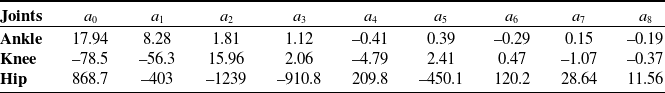
Table III. Uncertainty coefficient of Fourier function

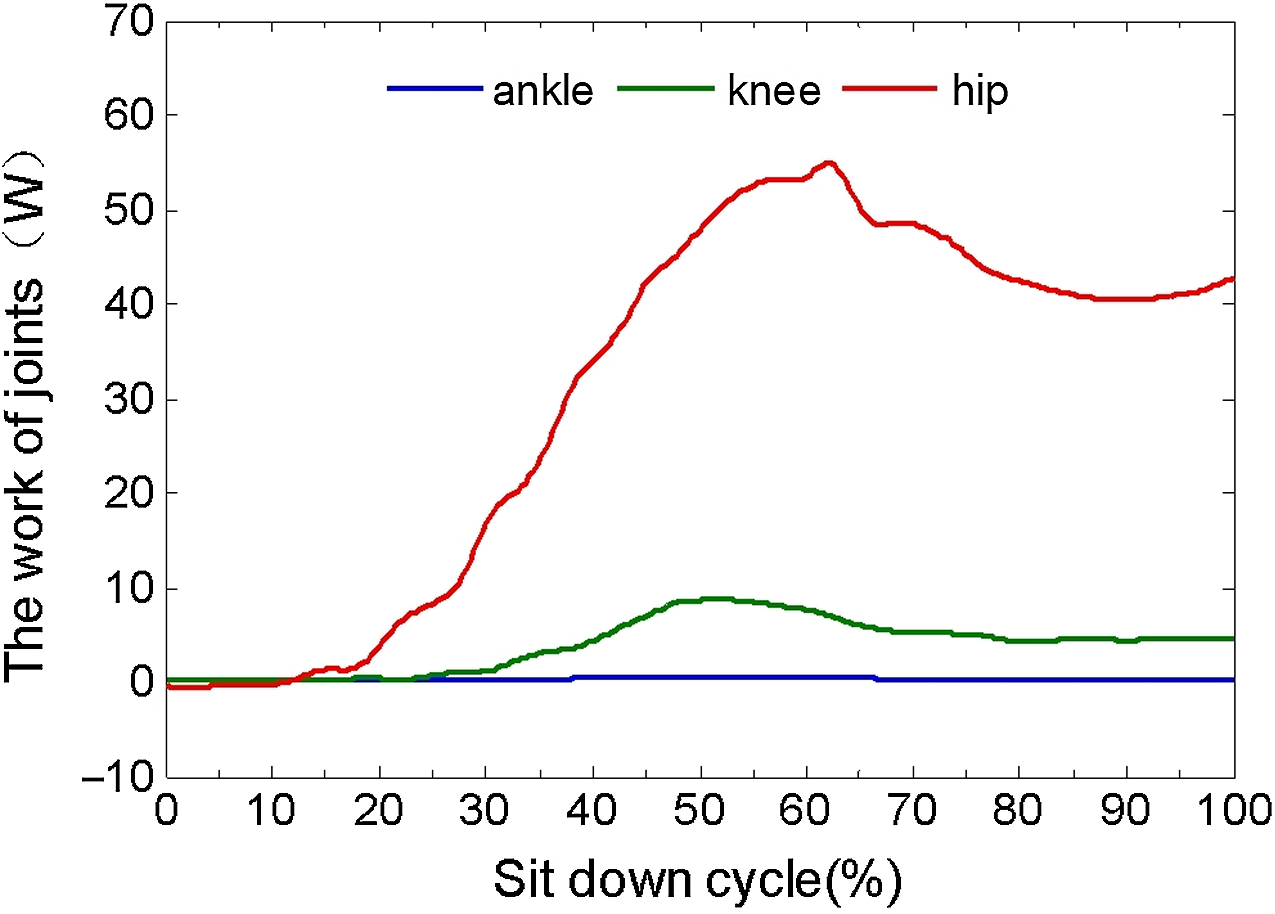
Figure 5. The work of joints (left leg).
2.2. Structural design of unpowered lower extremity exoskeleton
2.2.1. Design principles of elastic energy storage element
Modular design is basically to decompose complex systems into simple modules in order to more efficiently organize complex designs and processes. Its advantages include design flexibility, augmentation, cost reduction, and so on [Reference Starr30]. So the unpowered lower limb exoskeleton is proposed in this paper, as shown in Fig. 6. It has simple structure, convenient wearing, lightweight, and adapt to different gait, and helps the patient to walk.
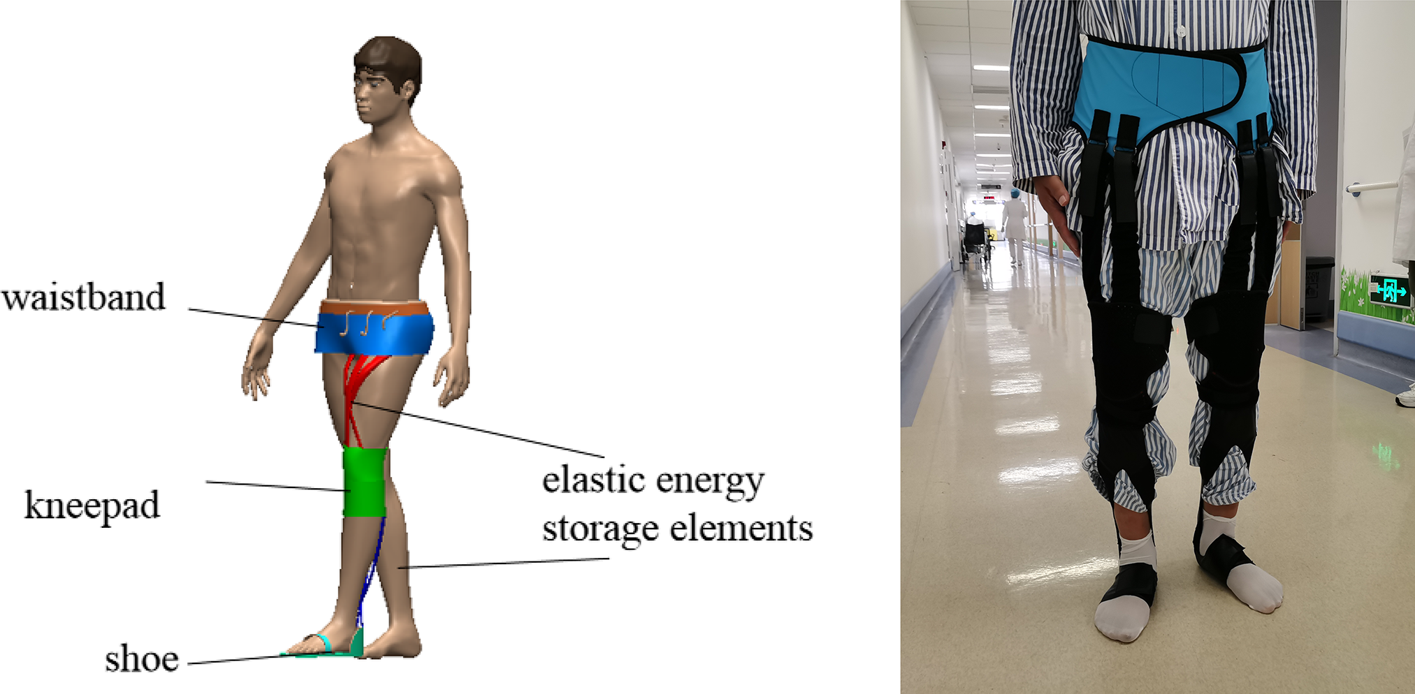
Figure 6. Structure of unpowered lower limb exoskeleton.
This exoskeleton consists of elastic energy storage elements, clutch devices, waistband, kneepad, shoe, and so on. Wherein, the elastic energy storage elements are natural rubber latex band, which has good flexibility, dry cleaning, no shrinkage, chlorine resistance, light fastness, and sweat resistance. And the waistband is Spandex; it has had an impact on fashion high and low, casual and formal, outer and under.
Human power is an attractive energy source; it contains kinetic energy, potential energy, and muscles works. Wherein the muscle converts food into positive mechanical work with peak efficiencies of approximately 25%, and about 30% positive mechanical of muscle for the body move forward.
There are multiple muscles in the ankle, such as the peroneus longus and peroneus brevis; they allow the ankle to bend downward and outward. The gastrocnemius and soleus are connected to the calcaneus via the Achilles tendon; they enable the ankle to bend downward and upward. The posterior tibialis enables the foot to turn inward, but the anterior tibialis enables the ankle and foot to turn upward.
During the loading response and midterm of stance phase, the anterior tibial, gastrocnemius, and soleus are to take eccentric contraction; they maintain constant tension in the muscle as the muscle changes length, and to store the metabolic energy, which is similar to elastic energy storage elements. During late term of stance phase, they are taking concentric contraction, in which the muscles shorten due to the sliding filament mechanism, and metabolic energy was released, then they offer positive joint powers to propel the limb and body move upward and forward, the maximum of joint powers can approach to 3.6 W/kg [Reference Zhang21], as shown in Fig. 7.
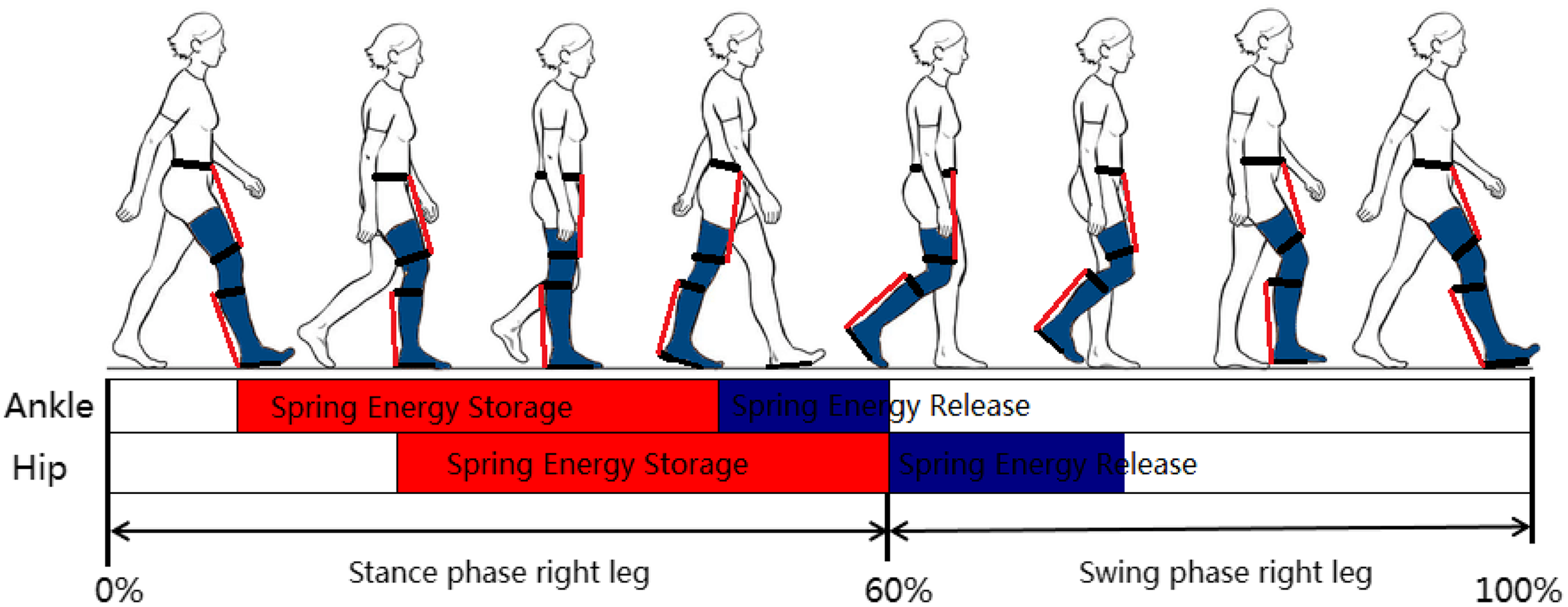
Figure 7. Energy storage and release of joints.
The dorsiflexion and flexion of ankle are the major motion during walking; the elastic energy storage element was installed on the front side of the shank reflects on the motion of toe, then it was installed on the both sides of the shank restrictions on the performance of exoskeleton, so the back side of the shank is an ideal location to install elastic energy storage element. The mechanical energy is converted into elastic potential energy that stored in the elastic energy storage element, during the loading response and midterm of stance phase, and it is released during heel off.
Moreover, the hip muscles include pelvic and groin muscles, such as RF, semimembranosus, tensor fasciae latae, and sartorius; they are important for stabilizing the body and for moving the legs. The hip has complicated structure; the elastic energy storage element is difficult to install on the back and both side of the hip, so the front side of the thigh is an ideal location to install elastic energy storage element. During the loading response and midterm of stance phase, the mechanical energy is converted into elastic potential energy that stored in the elastic energy storage element, and it is released during toe off during the loading response and midterm of stance phase.
Taken together design principles of elastic energy storage element, the mechanical energy of limb is converted into the elastic potential energy of element during negative joint work, and the elastic potential energy of the element is released during positive joint work. Wherein, the positive joint work occurs when the muscles perform a concentric contraction while negative joint work occurs when the muscles elongate or stretch during an eccentric contraction. And the concentric contractions are the primary contributors that generate the work performed by the joint to increase the limb segment mechanical energy while eccentric contractions result in mechanical energy absorption as work is performed on the adjacent limb segments by an external force such as gravity. So the metabolic cost is associated with performing negative joint work or eccentric muscle contractions, and the cost is lower than that of positive joint work or concentric muscle contraction.
Gait energy contains the kinetic energy and gravitational potential energy of limbs; it is converted into elastic potential energy by the energy storage element, which is an important part in the unpowered exoskeletons. The energy storage element has several forms, such as helical spring [Reference Collins, Wiggin and Sawicki11, Reference Zhang21], BLS [Reference Nasiri, Ahmadi, Ahmadabadi and Syst22], pneumatic muscle [Reference Leclair, Pardoel, Helal and Doumit25], torsion springs [Reference Guan, Ji, Wang and Huang27], memory alloy [Reference Lee, Lee, Na, Ahn, Jung, Cheng, Kim, Jun and Kim31], and rubber [Reference Masood, Ortiz, Fernndez, Mateos and Caldwell32, Reference Di Natali, Poliero, Sposito, Graf, Bauer, Pauli, Bottenberg, De Eyto, O’Sullivan and Hidalgo33].
For the energy storage element with helical spring, the direction of output force is in accord with the axis of helical spring; it has lightweight, without damping, high reset performance, and connects to the two adjacent limbs. However, the helical spring needs bigger space because of the stretch/shrink of helical spring, and the spring is easy to shake during tension procedure.
Torsion springs are helical springs that exert a torque or rotary force. The ends of torsion spring is attached to the rotational center of joint, and the torsion spring tries to push them back to their original position when limbs moment, but it limits the motion performance of joints.
Energy storage element contains shape memory alloy (SMA), which has high power density and can be restored to their original shape by heating after every use, and it only has passive elastic and damping components for shock energy absorption. Moreover, energy storage element uses the PAM as a linear actuator; it has significant longitudinal forces, non-linear tensile, and stiffness behavior. But the propagation velocity of PAM is slow, which compared to biological muscles.
The elastic material includes thermoplastic elastomer (TPE), thermoplastic polyurethanes (TPU), rubber, latex, and so on. The TPE and TPU have high resilience, high strength, small deformation, and oil resistance. And the rubber and latex have high elasticity, heat resistance, wear resistance, flexibility, and elasticity. They are the optimal choice for energy storage element.
Combined with the torques and angles of joints in SD and SU, the stiffness of hip, knee, and ankle is obtained, as shown in Fig. 8. The RF, gracilis, and sartorius act on the hip during SD, and the flexion angle and torque of hip reach maximum $ 104^{\circ} $
, 31 Nm/kg, respectively. The extension angle and torque of hip gradually reduce to
$ 104^{\circ} $
, 31 Nm/kg, respectively. The extension angle and torque of hip gradually reduce to $ 10^{\circ} $
, –2 Nm/kg, according to linear regression analysis for the datum of torque and angle, then the stiffness of hip is 0.348 Nm/kg/deg. The gracilis, sartorius, and biceps femoris act on the knee during SD, and the flexion angle and torque of knee reach maximum
$ 10^{\circ} $
, –2 Nm/kg, according to linear regression analysis for the datum of torque and angle, then the stiffness of hip is 0.348 Nm/kg/deg. The gracilis, sartorius, and biceps femoris act on the knee during SD, and the flexion angle and torque of knee reach maximum $ 110^{\circ} $
, 5.5 Nm/kg, respectively, the extension angle and torque of knee gradually reduce to
$ 110^{\circ} $
, 5.5 Nm/kg, respectively, the extension angle and torque of knee gradually reduce to $ 5^{\circ} $
, –0.5 Nm/kg, respectively, and then the stiffness of knee is 0.047 Nm/kg/deg. Meanwhile, the torque of ankle is very small during SD and SU, the extension angle of ankle reaches maximum
$ 5^{\circ} $
, –0.5 Nm/kg, respectively, and then the stiffness of knee is 0.047 Nm/kg/deg. Meanwhile, the torque of ankle is very small during SD and SU, the extension angle of ankle reaches maximum $ 32^{\circ} $
, the torque of ankle ranged between
$ 32^{\circ} $
, the torque of ankle ranged between $ 0.95 \sim 1.01$
Nm/kg, and the stiffness of ankle is 0.002 Nm/kg/deg.
$ 0.95 \sim 1.01$
Nm/kg, and the stiffness of ankle is 0.002 Nm/kg/deg.
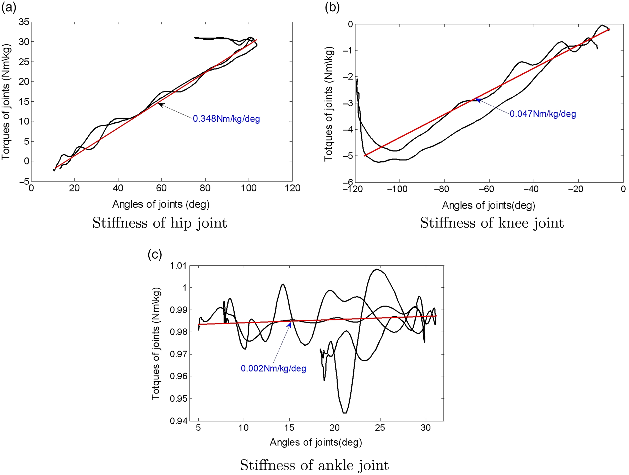
Figure 8. Stiffness of joints (left leg).
2.2.2. Structure and work mode of clutch device
The gait energy in energy storage element is stored and released by the clutch device, and this device has the advantages of small volume, good flexibility, low cost, and high efficiency. The clutch device is composed of elastic energy storage elements, support plate, swing component, and so on. The middle of elastic energy storage element has many barbs, the lower part of support plate has a baffle, and the swing component contains micromotor, wireropes, gear, gear belts, and pawl. The pawl rotates around the pivot point that fixed on support plate, as shown in Fig. 9.
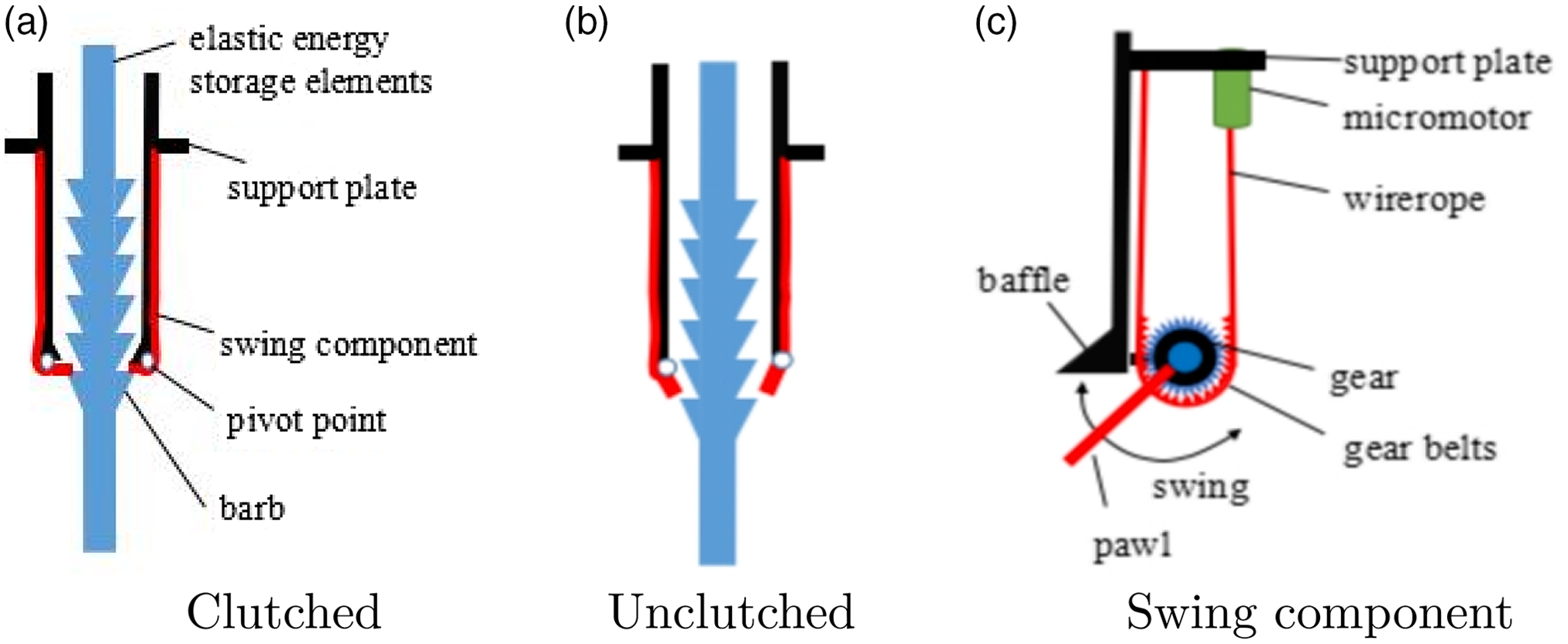
Figure 9. Structure of clutch device.
Take the clutch device of hip for example, the elastic energy storage elements were stretched and the gait energy is stored during the late term of stance phase, then the micromotor drive wireropes and gear belts move to baffle, the pawl engage with the barbs to restrict the elastic energy storage elements draw back. The elastic energy storage elements can not provide any forces to the hip joint and it not restrict the motion of thigh; during the early term of swing phase, the micromotor drive wireropes and gear belts move away to baffle when heel off state, the pawl disengage with the baffle, elastic energy storage element is shrunk, so the elastic potential energy is released to pull the thigh swing.
2.3. Motion characteristics of lower limbs during SD and SU
2.3.1. SD process
SD and SU movements are essential parts of daily human activity. SD is a prerequisite for most human activities, such as walking, running, and climbing stairs. Four phases have been recognized as crucial for the description and analysis of the SD movement: (1) The body’s center of gravity is located in the front third sacral vertebra about 7 cm, then the gluteus maximus, quadriceps femoris, triceps surae, and erector spinae work together to keep human body in a stable state; (2) The head, arms, and trunk rotate forward around the pelvis, the hip and knee joint in flexion and the ankle joint in dorsiflexion, and the buttocks start contacting the chair. Moreover, the chair has suffered an impact force by body; it hinders the body’s center of gravity move down toward; (3) the muscles in buttocks and waist helps the body move back toward, the body’s center of gravity at the center of the seat of the chair; (4) the position of foot and posture of body are adjusted slightly, the person sits in optimal state, as shown in Fig. 10.

Figure 10. Sit down process.
2.3.2. Contribution degree of muscles of joints
The skeletal muscles in the lower limb of body work together on the joints, and they help body walk in various complicated environments. When some skeletal muscles of joints were damaged, the abnormal gait of body was happened, such as the ducks step which cause by the gluteus medius muscle weakness, the drags step which cause by quadriceps femoris muscle weakness, and the strides step which cause by ankle dorsal extensor muscle weakness.
Muscle synergy is defined as a combination of the limited number of muscle activities, which has been considered useful for controlling a large number of degrees of freedom in the musculoskeletal system. The contribution degree is used to evaluate the muscles participation during walk; the muscle forces of joints are obtained by gait analysis and musculoskeletal system (Opensim), and the normalization processing of datum is carried out. According to Formulas (12), the contribution degree of muscles for the hip and knee joint of left leg is shown in Fig. 11.
 \begin{equation}\eta = \frac{{{f_i}}}{{{f_1} + {f_2} \cdots {f_n}}}\end{equation}
where $ f_i $
is the force for the ith muscle in joint.
$ f_i $
is the force for the ith muscle in joint.

Figure 11. Metabolic cost for some muscles and body (left leg).
The force of sartorius, gracilis, and RF is about $ [1.5\; 2.7] \times 10^{4} N $
,
$ [1.5\; 2.7] \times 10^{4} N $
, $ [1.45\; 1.65] \times 10^{4} N $
,
$ [1.45\; 1.65] \times 10^{4} N $
, $ [0 \; 0.2] \times 10^{4} N $
, respectively. The contribution degree of sartorius and gracilis is about
$ [0 \; 0.2] \times 10^{4} N $
, respectively. The contribution degree of sartorius and gracilis is about $ [0.5\; 0.65] $
,
$ [0.5\; 0.65] $
, $ [0.35 \; 0.55] $
, respectively. They are mainly acting on the hip flexion/extend during SD and SU. The force of sartorius, gracilis, the long head and short head of the biceps femoris is about
$ [0.35 \; 0.55] $
, respectively. They are mainly acting on the hip flexion/extend during SD and SU. The force of sartorius, gracilis, the long head and short head of the biceps femoris is about $ [1.7\; 2.8] \times 10^{4} N $
,
$ [1.7\; 2.8] \times 10^{4} N $
, $ [1.5\; 1.6] \times 10^{4} N $
,
$ [1.5\; 1.6] \times 10^{4} N $
, $ [0\; 1.5] \times 10^{4} N $
,
$ [0\; 1.5] \times 10^{4} N $
, $ [1.5\; 5] \times 10^{4} N $
, respectively. And their contribution degree is about
$ [1.5\; 5] \times 10^{4} N $
, respectively. And their contribution degree is about $ [0.26\; 0.32] $
,
$ [0.26\; 0.32] $
, $ [0.17\; 0.23] $
,
$ [0.17\; 0.23] $
, $ [0\; 0.22] $
,
$ [0\; 0.22] $
, $ [0.29 \; 0.53] $
, respectively. They help knee to flexion and extend. Besides, the sartorius and gracilis are involved in the motion of hip and knee during SD and SU.
$ [0.29 \; 0.53] $
, respectively. They help knee to flexion and extend. Besides, the sartorius and gracilis are involved in the motion of hip and knee during SD and SU.
3. Results
Energy cost is the energy contribution values from the macronutrients of fats, carbohydrates and proteins. Wherein, the resting energy cost is the minimal amount of energy required to support the body’s physiological functions; it is influenced by an individual’s amount of lean muscle mass, age, gender, and climate. During rest, various organs are responsible for consuming energy to support their functions. The resting energy cost is 1 met, and energy cost of sitting or writing is 2 met, running is about 3.3 $\sim$
38.7 met for normal people.
$\sim$
38.7 met for normal people.
The metabolic cost of muscle contains activation heat, maintenance heat, shortening/lengthening heat, and mechanical work rate of the contractile element (CE); it was expressed as the sum of four terms [Reference Umberger, Gerritsen and Martin34].
 \begin{equation}\dot E = {{\dot h}_A} + {{\dot h}_M} + {{\dot h}_{SL}} + {{\dot w}_{CE}}=\dot h_{AM}+\dot h_{SL} + \dot w_{CE}\end{equation}
where $ {{\dot h}_A} $
is the activation heat rate,
$ {{\dot h}_A} $
is the activation heat rate, $ {{\dot h}_M} $
is the maintenance heat rate,
$ {{\dot h}_M} $
is the maintenance heat rate, $ {{\dot h}_{SL}} $
is the shortening/lengthening heat rate,
$ {{\dot h}_{SL}} $
is the shortening/lengthening heat rate, $ {{\dot w}_{CE}} $
is the mechanical work rate of the CE.
$ {{\dot w}_{CE}} $
is the mechanical work rate of the CE. $ \dot h_{AM}=\dot h_A + \dot h_M = 1.28 \times \%FT +25 $
.
$ \dot h_{AM}=\dot h_A + \dot h_M = 1.28 \times \%FT +25 $
.
FT is the human fast twitch muscle fibers.
ST is the human slow twitch muscle fibers.
The shortening heat coefficients for ST and FT fibers are thus calculated as
 \begin{equation}{{\dot a}_{S(ST)}} = \frac{{4 \times 25}}{{{{\tilde V}_{CE(MAX - ST)}}}}\end{equation}
 \begin{equation}{{\dot a}_{S(FT)}} = \frac{{4 \times 25}}{{{{\tilde V}_{CE(MAX - FT)}}}}\end{equation}
where ${{{\tilde V}_{CE(MAX - ST)}}} $
,
${{{\tilde V}_{CE(MAX - ST)}}} $
, $ {{{\tilde V}_{CE(MAX - FT)}}} $
is defined by the Hill coefficients. The shortening heat rate is then given by
$ {{{\tilde V}_{CE(MAX - FT)}}} $
is defined by the Hill coefficients. The shortening heat rate is then given by
 \begin{equation}{{\dot h}_{SL}} = - {a_{S(ST)}}{{\tilde V}_{CE}}(1 - \% FT/100) - {a_{S(FT)}}{{\tilde V}_{CE}}(1 - \% FT/100)\end{equation}
The mass specific mechanical work rate is given by
 \begin{equation}{{\dot w}_{CE}} = \frac{{{F_{CE}}{V_{CE}}}}{m}\end{equation}
m is the mass of the muscle. Combined with Formulas (13)–(18), the metabolic cost of muscle is obtained from the following equation:
 \begin{equation}\begin{aligned}&if \; {L_{CE}} \le {L_{CE(OPT)}}; \dot E = {{\dot h}_{AM}}{A_{AM}}S- ({F_{CE}}{V_{CE}})/m+W_{V1}\\&if \; {\tilde V}_{CE} \le 0 ; {W_{V1}} = ( - {a_{S(ST)}}{{\tilde V}_{CE}}(1 - \% FT/100)\\&-{a_{S(ST)}}{{\tilde V}_{CE}}(1 - \% FT/100)){A_S}S\\&if \; {\tilde V}_{CE} > 0 ;{W_{V1}} = {a_L}{{\tilde V}_{CE}}AS\\&if \; {L_{CE}} > {L_{CE(OPT)}} ;\dot E = (0.4 \times {{\dot h}_{AM}} + 0.6 \times {{\dot h}_{AM}}{F_{ISO}}){A_{AM}}S \\&+ ({F_{CE}}{V_{CE}})/m+{W_{V2}}\\&if \; {\tilde V}_{CE} \le 0; \\&W_{V2} = ( - {a_{S(ST)}}{{\tilde V}_{CE}}(1 - \% FT/100) - {a_{S(ST)}}{{\tilde V}_{CE}}(1 - \% FT/100))){F_{ISO}}{A_S}S\\&if \; {\tilde V}_{CE} > 0;{W_{V1}} = {a_L}{{\tilde V}_{CE}}{F_{ISO}}AS\end{aligned} \end{equation}
where S is a scaling factor; under the anaerobic condition, the value of S is 1, but it is 1.5 under aerobic conditions; it is needed to account for the length and activation dependence $ {\dot h}_{AM} $
and
$ {\dot h}_{AM} $
and $ {\dot h}_{SL} $
, factors for scaling
$ {\dot h}_{SL} $
, factors for scaling $ {\dot h}_{AM} $
and
$ {\dot h}_{AM} $
and $ {\dot h}_{SL} $
that depend on A.
$ {\dot h}_{SL} $
that depend on A.
 \begin{equation}\begin{aligned}&A = \left\{ {\begin{array}{*{20}{c}} {STIM\begin{array}{*{20}{c}} {} & {\begin{array}{*{20}{c}} {{\rm{when}}} & {STIM > ACT} \\[5pt] \end{array}} \\ \end{array}} \\[5pt] {(STIM + ACT)/2\begin{array}{*{20}{c}} {{\rm{ when}}} & {STIM \le ACT} \\ \end{array}} \\ \end{array}} \right.\\&A_{AM} = {A^{0.6}},{A_S} = {A^{2.0}}\end{aligned}\end{equation} $ F_{CE} $
is the force of CE,
$ F_{CE} $
is the force of CE, $ V_{CE} $
is the velocity of CE.
$ V_{CE} $
is the velocity of CE. $ {{\tilde V}_{CE}} $
is the speed of CE,
$ {{\tilde V}_{CE}} $
is the speed of CE, $ {F_{ISO}}$
is the force of isometric of muscle, STIM is an idealized neurocontrol signal, ACT is muscle active state.
$ {F_{ISO}}$
is the force of isometric of muscle, STIM is an idealized neurocontrol signal, ACT is muscle active state.
The musculoskeletal and metabolic cost models are used to estimate metabolic energy by Opensim software, and the steps for computing metabolic cost of musculoskeletal simulation in OpenSim are shown in Fig. 12. The scale model is scaled to match the anthropometry of subject; the inverse kinematics (IK) is solved to determine the joint angles that best reproduce the raw marker data obtained from Vicon system. The RRA is applied to make for the joint angles and translations of model, which more dynamically consistent with the measured ground reaction forces and moments. The CMC is used to generate a set of muscle excitations that produce a coordinated muscle-driven simulation of the subjects movement. According to the above data and the Umberger 2010 MuscleMetabolicsProbe, the structural parameters of energy storage elements are shown in Table IV. Wherein, the stiffness of energy storage elements for hip and ankle is $ k_{1} $
=0.2, 0.4, 0.6, 0.8 N/mm;
$ k_{1} $
=0.2, 0.4, 0.6, 0.8 N/mm; $ k_{2} $
=0.5, 0.6, 0.7, 0.8 N/mm, respectively. So the metabolic cost of musculoskeletal model with exoskeleton was obtained, as shown in Fig. 13.
$ k_{2} $
=0.5, 0.6, 0.7, 0.8 N/mm, respectively. So the metabolic cost of musculoskeletal model with exoskeleton was obtained, as shown in Fig. 13.

Figure 12. Steps for generating metabolic cost of musculoskeletal simulation in OpenSim.
Table IV. Structure parameters of unpowered lower limb exoskeleton


Figure 13. Metabolic cost for some muscles and body (left leg).
In the early stage of SD, standing balance of body was broke, and the gracilis femoris and long head of the biceps femoris do negative work because of the eccentric contraction of muscles, and their energy cost steadily reduces about 0.7 J, 0 J; the RF, sartorius, and short head of the biceps femoris do positive work by the isokinetic contraction of muscles, and their energy cost steadily increases about 3.5 J, 2.1 J, and 3.9 J, respectively. In the middle stage of SD, gracilis and long head of the biceps femoris provide positive work to help the hip flex, their energy cost steadily increases about 1.5 J, 8.4 J. The RF, sartorius, and the short head of the biceps femoris do positive work, and their energy cost steadily reduces about 0.5 J, 0.5 J, 0.2 J. In the final stage of SD, gracilis, sartorius, and long head of the biceps femoris do negative work by gravity of body, the hip continues flex until the buttocks contact with the seat of the chair, then their energy cost steadily reduces about 0.5 J, 0.5 J; RF and sartorius do positive work to help the knee maintain flexion, and their energy cost steadily increases about 4 J, 1.6 J. Besides, the short head of the biceps femoris does small positive work, and its energy cost increases about 2.5 J. During the SU stage, the gracilis, RF, sartorius, and biceps femoris do positive work to help the hip and knee extending, and their energy cost steadily increases about 3.1 J, 1.5 J, 2 J, 2.2 J; but the RF does negative work, its energy cost reduces about 1.6 J.
Person SD under the exoskeleton conditions; the metabolic cost reduces about 13%, 9%, 68% for the gracilis, RF, and long head of the biceps femoris, but the metabolic cost of sartorius and the short head of the biceps femoris increases about 16%, 7%, and then the total metabolic cost reduces about 14%; during SU stage, the metabolic cost of the gracilis, RF, and long/short head of the biceps femoris increases about 22%, 33%, 208%, and 46%, but the metabolic cost of sartorius reduces about 39%; then the total metabolic cost increases about 25.6%, because of the elastic energy storage elements hinder the elongation of muscles. Moreover, the lower extremity exoskeletons can cause muscle activity happen much sooner.
4. Conclusion
The aim of the present work was to design an unpowered lower limb exoskeleton which might be used by elderly people. It reduces the metabolic cost of body for normal daily living, and the mobility functionalities of lower extremity exoskeletons adapt to different kinds of occasions, such as straight walking on ground, bending down, walking up/downstairs, stepping over objects, and sit-to-stand transfers. Besides, the exoskeleton has many advantages such as comfortable, good fit, easy to put on/take off (don/doff), wearing without help, and lightweight.
The numerous numbers of researches and institutes make a profound study on the unpowered lower limb exoskeletons, but the gait energy is one of the key factors for the exoskeleton; it is composed of the swing and torso energy from sagittal and frontal dynamics (3LP dynamics), velocity redirection of center of mass (CoM), ground clearance, and weight support energy [Reference Faraji, Wu and Ijspeert35]. Moreover, the gait energy is closely related to the size, weight of body, the velocity of limbs, and trunk, so its utilization efficiency needs to be improved, which helps patients with abnormal gait to convenient, low cost, and stable walking.
The optimum design of structure and position of energy storage element base on the performance of muscle, which collects enough gait energy. For the helical spring, it needs bigger space and easy to shake during straining state. Torsion springs are attached to the rotational center of joint; it limits the motion performance of joints. The force transmissibility performance of SMA and PAM is slow compared to biological muscles. TPE and TPU have high resilience, high strength, and small deformation. In addition, the rubber and latex have high elasticity, heat resistance, wear resistance, flexibility, and elasticity. The mixture of them is the optimal choice for energy storage element.
The clutch device changes the work ways of energy storage element, it causes the gait energy is stored and released at appropriate time, which consider activation degree of muscle. And the muscles in limb take eccentric contraction to produce the mechanical energy of joints, which change into elastic potential energy of energy storage element. When the clutch device is unclutched, the elastic potential energy of energy storage element is released, then it offers positive joint powers to propel the limb and body move.
The paths of the forces for the energy storage element determine the quality and efficiency of energy storage element; bionic design of the paths of the forces for the energy storage element is based on transmission path of muscle. There are three main methods of description transmission path of muscle: lines enveloping, polygonal line with starting and ending points and curve path with obstacle [Reference Tang and Wang36]. Besides, the performance evaluation method for the unpowered lower extremity exoskeletons needs system optimization and adds some sensing elements to test the human condition and operating status of exoskeletons.
Acknowledgements
Yongfeng Wang helped in conceiving the study concept and design, acquiring the data, analyzing and interpreting the data, and drafting the manuscript. Feng Yu and Yanan Diao helped in acquiring the data, analyzing and interpreting the data, and drafting the manuscript. Guoru Zhao and Guanglin Li helped in conceiving the study concept and design, drafting and revising the manuscript, obtaining funding, and supervising the study. The authors would like to acknowledge Kai Zhen, Lili Liu, and Jing Yang for their help in collecting and analyzing the data of body, and operating of the Vicon equipment. All authors have read and agreed to the published version of the manuscript.
Funding
This study has been financed partially by the National Key R&D Program of China (2019YFB1311400/01, 2018YFC2001400/04), Shenzhen Science and Technology Development Fund (JCYJ20170818163505850), Shandong Key R&D Program (2019JZZY011112), the Innovation Talent Fund of Guangdong Tezhi Plan (2019TQ05Z735), High Level-Hospital Program, Health Commission of Guangdong Province (HKUSZH201901023), Guangdong-Hong Kong-Macao Joint Laboratory of Human-Machine Intelligence-Synergy Systems (2019B121205007), Hubei Key Laboratory of intelligent Conveying technology and device, Hubei Polytechnic University (2020XZ106, 19XJK16R), and the Key Project of Scientific Research Plan of Education Department of Hubei Province (No. D20204501).
Institutional Review Board Statement
Not applicable. Informed Consent Statement: Not applicable.
Conflicts of Interest
The authors declare that the research was conducted in the absence of any commercial or financial relationships that could be construed as a potential conflict of interest.
Supplementary Material
To view supplementary material for this article, please visit https://doi.org/10.1017/S0263574721001077.


 Open access