


Introduction
The development of the shape memory alloy began in 1932. Shape memory alloy is a material that “remembers” its original shape and will return to its pre-deformed shape when heated. Since then, the shape memory alloy has attracted a lot of research interest because of their possible application as actuators. In order to advance the application, it is important to have an in-depth understanding of the microstructural mechanism of the shape memory behavior.
Numerous researchers experimentally examined the shape memory phenomenon [Reference Chang1, Reference Buehler, Gilfrich and Wiley2, Reference Eggeler, Hornbogen, Yawny, Heckmann and Wagner3]. Chang [Reference Chang1] discovered the phase transformation reversibility of Au–Cd alloys. Buehler et al. [Reference Buehler, Gilfrich and Wiley2] observed the phase transformation of Ti–Ni alloys through X‐ray diffraction and dilation studies. But not so many investigations were carried out at microscopic levels [Reference Wang, Huang, Ren, Nie, Wang, Liu, Deng, Choo, Liaw, Brown and Zuo4, Reference Cong, Rule, Li, Lee, Zhang, Wang, Hao, Wang and Huang5], which is still relatively difficult despite recent advancement in microscopy. Therefore, computer simulation techniques, especially the molecular dynamics (MD) method, are effective tools to further understand and clarify the atomistic mechanism. Some researchers have investigated the crystal structures, thermal stability, and transformation of the martensite and austenite phases [Reference Rubini and Ballone6, Reference Ishida, Motoyama, Mae and Hiwatari7, Reference Pun and Mishin8, Reference Clapp, Rifkin, Kenyon and Tanner9, Reference Shao, Clapp and Rifkin10, Reference Uehara and Tamai11]. Rubini et al. [Reference Rubini and Ballone6] studied the stability of the body-centered-cubic (BCC) structure and the martensite phase of Ni–Al alloys using MD simulations with embedded atom method (EAM) potential. In their simulations, they found that the BCC structure is rather stable at high temperature. Ishida et al. [Reference Ishida, Motoyama, Mae and Hiwatari7] observed thermally induced martensitic and reverse martensitic transformations using modified EAM potential. Uehara et al. [Reference Uehara and Tamai11] have performed MD simulations with EAM potential to study the relationship between Ni-composition ratio and the martensite phase at different temperatures and concluded that martensite phase only appeared at low temperature with Ni composition more than 62%. The interatomic potential employed in MD simulation is crucial in characterizing the material behavior. Hence, some researchers tried to improve the interatomic potential function so that proper representation of the stable crystal structure at various conditions, i.e., temperature, pressure, and alloy composition, could be possible [Reference Farkas, Mutasa, Vailhe and Ternes12, Reference Kastner13, Reference Kastner14, Reference Ozgen and Adiguzel15, Reference Ozgen and Adiguzel16, Reference Ackland, Jones and Noble-Eddy17].
Some research focused on the microscopic mechanism of stress-induced martensitic transformation of shape memory alloys. Uehara et al. conducted a series of simulations by applying shear deformation and found that some of the variants with unstable orientations rearranged layer-by-layer are the key mechanism of the deformation [Reference Uehara and Tamai11, Reference Uehara, Masago and Inoue18, Reference Uehara and Tamai19, Reference Uehara, Tamai and Ohno20]. Sato et al. [Reference Sato, Saitoh and Shinke21] and Park et al. [Reference Park, Gall and Zimmerman22, Reference Park and Ji23, Reference Ji and Park24] studied the uniaxial loading simulation of Ni–Ti and silver nanowires and observed the phase transformation mechanism and pseudoelastic behavior. There are many studies on the phenomenon of phase transformation, pseudoelasticity, and thermal shape memory mechanism after loadings. However, it is still difficult to explain the microstructural mechanism of functional fatigue for shape memory alloy under cyclic loading, which is crucial to the application. Functional fatigue is refereeing to the loss of shape memory capability with increasing cycle numbers. Functional fatigue, as well as structural fatigue, will limit the service life of shape memory components.
In this research, we will attempt to explore the underlying mechanism of functional fatigue. In real application, shape memory alloy is polycrystalline with grain size around several hundred microns. Uehara et al. [Reference Uehara, Asai and Ohno25] proposed a multigrain model with several combinations of grain shape and crystal orientations and observed a smoother stress–strain curve under shear loading. The multigrain model with grain size of few nanometers considered in the literature [Reference Uehara, Asai and Ohno25] is still too simple to represent realistic alloys. However, it is time-consuming or not feasible to run a representative polycrystalline model with enough grains of size around several hundred microns under cyclic loading to investigate the microstructural mechanism of functional fatigue. In order to provide insight into the problem, instead of considering the statistical and collective behavior of many grains with various crystallographic orientations under cyclic external loading, the behavior of one grain is examined. Each grain inside the polycrystalline alloy would have its own crystal orientation as well as loading whose combinations could be infinite. In order to fully understand the grain behavior, the grain with fixed orientation, which could be approximately treated as one single crystalline material, under different loading conditions is considered. Various combinations of crystal orientations and loadings on the grain could be resolved to one of the loading conditions following stress transformation. Hence, the single crystalline Ni–Al alloy will be subjected to various loading conditions, e.g., uniaxial tension along different directions, pure shear, and biaxial loading, till yielding takes place at low temperature. The shape restoring ability of the plastically deformed Ni–Al alloy by heating to high temperature will be examined. The phase transformation of Ni–Al alloy for various Ni composition ratios will be first investigated to verify the existence of austenite and martensite phases.
Results and discussion
The cooling and heating process is carried out on Ni–Al alloy with several Ni composition ratios to observe the phase transformation behavior. Various loadings are applied on 68% Ni–Al alloy till plasticity takes place, and the plastically deformed model is heated up in order to examine whether it could restore to the original shape at high temperature.
Phase transformation temperature of Ni–Al alloys
The equilibrium length and angle of the model with various Ni compositions at 1700 K is shown in Fig. 1. It is noticed that Ni–Al alloys remain cubic structure at high temperature irrespective to Ni composition ratios. Hence, we set the equilibrium state at 1700 K as the referenced lattice length (a xo, a yo, a zo) and angle  $\left( {{\pi \over 2}} \right)$. The equilibrated lattice lengths and angles during the cooling and heating process will be compared with the referenced state at 1700 K, and the normal strains (εx, εy, εz) and shear strains (γxy, γxz, γyz) at different temperatures are defined as
 $${\varepsilon _{x,y,z}} = {{{a_{x,y,z}} - {a_{xo,yo,zo}}} \over {{a_{xo,yo,zo}}}}\quad ,$$
 $${\gamma _{xy,xz,yz}} = {\pi \over 2} - {\theta _{xy,xz,yz}}\quad .$$
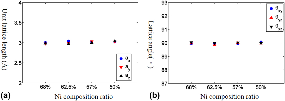
Figure 1: The equilibrium lattice structure for Ni–Al alloy with various Ni composition ratios at high temperature (1700 K). (a) Lattice length and (b) lattice angle.
The thermally induced normal and shear strains of Ni–Al alloys with different composition ratios are plotted in Fig. 2. From Figs. 2(a)–2(e), it is easily noticed that both normal and shear strains change dramatically at certain temperature range, at which phase transformation takes place, except for the 50% Ni–Al model. It turns out that Ni–Al alloy transforms from cubic structure (austenite) at high temperature into monoclinic one (martensite) at low temperature. Take 68% Ni–Al alloy as an example, two axes, i.e., y and z, of the cubic crystal structure contract while one axis elongates. Moreover, the crystal tilts in the y–z plane while keeping the x–y and x–z axes perpendicular. It is worth to point out that the contracting and elongating axes as well as tilting direction depend on the simulated model. Since the aluminum atoms are randomly replaced by nickel ones, another model of 68% Ni–Al alloy would deform into different variants of martensite structure as tested out in the simulation. From Fig. 2(f), it is interesting to observe that the volumetric thermal expansion coefficients (α) are about the same irrespective to Ni composition ratios since the volume dilatation  $\left( {{{\Delta V} \over V}} \right)$ is equal to the sum of the normal strains, i.e., ${{\Delta V} \over V} = {\varepsilon _x} + {\varepsilon _y} + {\varepsilon _z} = \alpha \Delta T$.
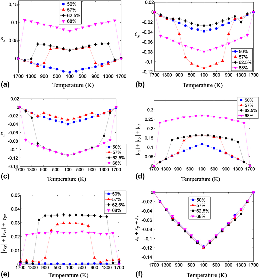
Figure 2: The strain-temperature relation under cooling and heating process for Ni–Al alloy with various Ni compositions. (a) εx, (b) εy, (c) εz, (d) the sum of the absolute of normal strains, (e) the sum of the absolute of shear strains, and (f) the sum of the normal strains.
At current study, the phase transformation temperature is determined within 200 K interval and it is observed that the phase transformation temperature region is significantly affected by Ni composition ratio. As the Ni composition increases in Ni–Al alloy, the phase transformation temperature becomes higher. Moreover, there is no observed phase change for 50% Ni–Al alloy. Some researchers reported different phase transformation temperatures, i.e., thermal hysteresis, in the continuous heating and cooling process [Reference Pun and Mishin8]. However due to the intrinsic time limitation of the MD, the heating/cooling rate is extremely high in the simulations. Sometimes, numerical overheating or overcooling might happen since the energy is continuously adding/removing before reaching equilibrium. Hence, the quasistatic thermal process is adopted to make sure the equilibrium state is reached at each temperature. In our simulation, 62.5% Ni–Al model does show different phase transformation temperature ranges in the cooling and heating process, i.e., austenite to martensite phase at 1100–1300 K and martensite to austenite phase at 1300–1500 K. The phase transformation temperature is reported to fall within 100–300 °C in experiment depending on the Ni composition [Reference Jani, Leary, Subic and Gibson26]. It is worth to mention that it is not the objective of this research to pinpoint the phase transformation temperature or clarify whether the phase transformation is first or second order since quantitative determination of phase transformation behavior would be significantly affected by the employed interatomic potential.
The shape recovery behavior of 68% Ni–Al alloy
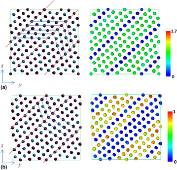
Various loading conditions, e.g., uniaxial, shear, and biaxial, are applied on 68% Ni–Al alloy bulk at 200 K incrementally till the corresponding stress drops, at which it is identified as plasticity taking place. From the inspection of the atomic configuration, it is observed that the 68% Ni–Al alloy retains martensite phase at 200 K. However, the martensite structure is monoclinic and the loading could not be easily applied on an inclined parallelepiped. Hence, the atomic model is first equilibrated under NTP ensemble at 200 K with zero pressure (normal stresses), while the periodic box remaining at cuboid shape. Thus, the model is pre-stressed along the y–z direction. The common neighbor parameter (CNP) [Reference Tsuzuki, Branicio and Rino27], which combined the advantages of both common neighbor analysis (CNA) and centrosymmetry parameter (CSP) analyses, is employed to describe the neighboring atom configuration. The zero CNP value indicates that the neighboring atomic configuration is BCC or FCC while a much higher value represents stacking fault or dislocation core structure.
The strain and stress relations under uniaxial and shear loadings are shown in Figs. 3(a) and 3(b), respectively. It is observed that the stress would suddenly drop at some strains depending on the loading conditions. The atomic configurations and CNP plot before and after the stress drop for uniaxial loading along the y direction are illustrated in Figs. 4(a) and 4(b). The atomic configurations and CNP plots are also put together side-by-side for a clear demonstration of the atomic movements. With the visual aid of CNP value, it is easier to identify the twining plane, which exists in between the rows with zero CNP value. The blue and red lines on the atomic configuration plot are drawn for visualization assistance to identify the twin boundary planes and twinning directions. Before stress drop, the twining planes already exist in martensitic state and most CNP values are relatively close to zero, which shows most of the atoms are arranged regularly as FCC crystal structure except around twinning planes. After stress drop, it is clear to observe that the twin boundary planes shift one or two rows along parallel direction in Fig. 4(b). The atomic configuration change before and after stress drop under uniaxial loading along the x and z directions is similar and, hence, is omitted for simplification. Figures 5(a) and 5(b) show the atomic configuration change under γyz shear loading. From the plot comparison, it is noticed that the twining planes re-orient and twinning direction changes. It should be mentioned that the pre-exist shear stress is not causing any twining plane change, which could be easily identified from the atomic configuration.
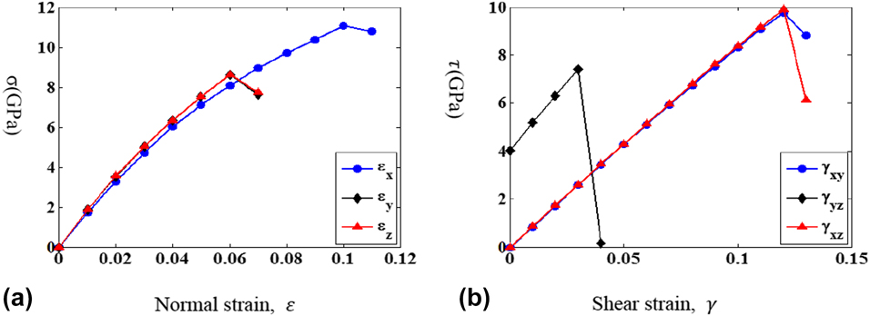
Figure 3: The stress and strain relationship for (a) uniaxial and (b) shear loadings.
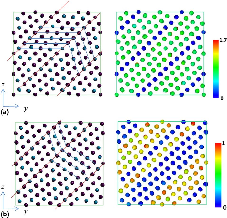
Figure 4: Atomic configurations (left) and CNP plot (right) of 68% Ni–Al alloy under applied εy loading at different states. (a) Before and (b) after stress drops.
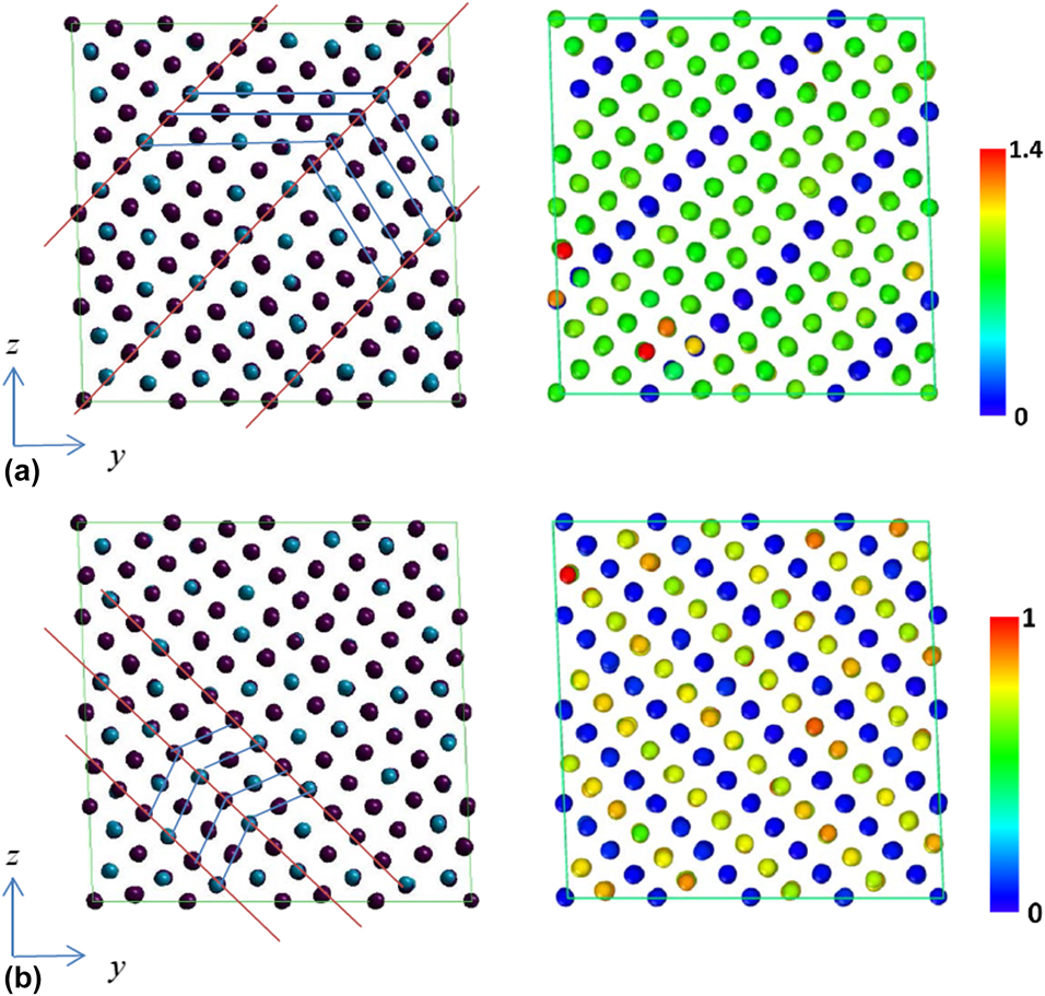
Figure 5: Atomic configurations (left) and CNP plot (right) of 68% Ni–Al alloy under applied γyz loading at different states. (a) Before and (b) after sudden stress changes.
Figures 6(a) and 6(b) demonstrate the atomic configuration change under (−ε, ε, 0) biaxial strain loading. Before stress drop, the twining planes already exist in martensitic state and most CNP values are close to zero as shown in Fig. 6(a). After stress drop, some atoms become misaligned and the CNP value for each atom becomes higher as illustrated in Fig. 6(b), which are identified as the appearance of stacking faults or dislocations. Overall, it is observed that the atomic configuration change for the test loadings could be attributed to the movement or re-orientation of the twinning planes and the appearance of stacking faults or dislocations. These are considered as mechanisms of plasticity, which could release the applied deformation energy. The plastic deformation is mechanically irreversible, which means the original shape is not recovered even when the external load is released.
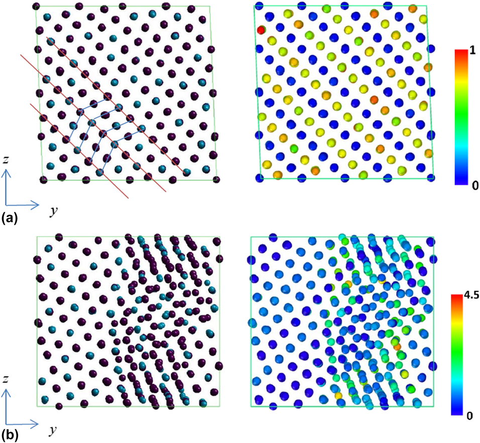
Figure 6: Atomic configurations (left) and CNP plot (right) of 68% Ni–Al alloy under applied (−ε, ε, 0) loading at different states. (a) Before and (b) after stress drops.
In order to examine whether the plastically deformed 68% Ni–Al alloy would restore to its original shape, the deformed model is heated up to 1700 K, without external loading and the atomic configuration at high temperature is inspected for respective loading conditions. Since the temperature is high, atoms are thermal fluctuated significantly. However, it is quite easy to identify whether the alloy restore to austenite state by examining the unit lattice length and lattice angle. It is found that the plastically deformed shape recovers at high temperature for εy and γyz loading cases, where the average lattice length is 3.0 Å and the lattice angle is  ${\pi \over 2}$ as shown in Figs. 7(a) and 7(b). However, the lattice angle between y and z axes could not restore to ${\pi \over 2}$ at 1700 K for (−ε, ε, 0) as illustrated in Fig. 7(a). From the inspection of all the atomic configurations at 1700 K after various loadings, it is found that once stacking faults or dislocations appear in the yielding process, there is no shape recovery above phase transformation temperature.
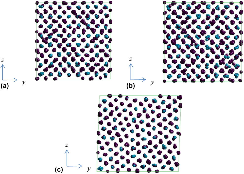
Figure 7: Atomic configurations of 68% Ni–Al alloy at 1700 K after yielding. The loading conditions are (a) εy, (b) γyz and (c) (−ε, ε, 0).
The yield strain, maximum shear stress at the yield strain, and shape recovery at high temperature for various loading conditions are summarized in Table I. The maximum shear stress is calculated from the corresponding principal stresses at yield strain. From Table I, there is no direct dependence between yield strain and the shape recovery capability. In some loadings, it is more favorable to have twining plane re-orientated or moved. However, in some loading conditions, the stacking faults or dislocation nucleation is the major yielding mechanism instead of twinning and the corresponding maximum shear stress tends to be higher. Once stacking faults or dislocation appears, the deformation could not be restored through heating up to phase transformation temperature.
TABLE I: The yield strain, maximum shear stress at yield strain, and shape recovery capability at high temperature for various loading conditions.
Based on our findings, it might be possible to depict the microscopic mechanism of functional fatigue existed in the cyclic application of shape memory alloy. As for the polycrystalline shape memory alloy under uniform strain loading, each grain, which could be treated as single crystal, will subject to loading along different crystallographic directions. As the applied strain increases, some of the grains might have stacking faults or dislocations nucleated and, thus, could not be restored through heating. These distorted grains might impose residual stress and further induce more stacking faults or dislocations in the following loading cycle. Hence, the microstructures gradually change under cyclic loading and the alloy loses its shape memory capability eventually. Our postulation is relatively simple and the grain boundary effect is totally ignored in the discussion. A more detailed model including grains under cyclic loading is required in order to fully understand the mechanism.
Conclusion
The phase transformation phenomenon of Ni–Al alloy was examined for various nickel composition ratios using MD simulation through quasistatic cooling and heating process. The phase transformation between monoclinic (martensite) and cubic (austenite) structures was identified using thermal strain change with respect to the referenced state at high temperature. It was observed that the phase transformation temperature is significantly affected by nickel composition ratio. Moreover, there is no observed phase change in 50% Ni–Al alloy.
Various loadings were applied on 68% Ni–Al alloy at low temperature till plasticity takes place and the plastically deformed models were heated above phase transformation temperature in order to examine whether the models could restore to their original shape. It was observed that there is no direct dependence between yield strain and the shape recovery capability. In some loadings, it is more favorable to have movement or re-orientation of the twining planes as yielding mechanism, while the stacking faults or dislocation nucleation is the cause for the others. The corresponding maximum shear stress for yielding mechanism involving only twinning plane motion tends to be lower. Once stacking faults or dislocations appear, the deformation is not recoverable through heating up to phase transformation temperature. Our findings could provide a possible explanation for microscopic mechanism of functional fatigue existed in the cyclic application of shape memory alloy. However, the postulation is still relatively simple and the grain boundary effect is totally ignored in the discussion. A more detailed model including grains under cyclic loading is required in order to fully understand the mechanism of functional fatigue.
Simulation model and method
MD simulation is employed to study the phase transformation behavior of Ni–Al alloy with various Ni compositions under the cooling and heating process. Different loading conditions will be applied to the 68% Ni–Al bulk till plasticity at low temperature and the shape after heating will be observed in order to study whether the deformed alloy will remember its original shape.
Models
The Ni–Al model is constructed from B2 parent structure with equal amount of Ni and Al atoms as shown in Fig. 8. In total, there are 1024 atoms in the model, composed of 8 units in all three directions. In order to construct models with different Ni composition ratios (68%, 62.5%, and 57%), aluminum atoms are randomly chosen and replaced by nickel ones. The crystal orientation of Ni–Al alloy is x[100], y[010], and z[001]. Periodic boundary condition is applied on all three directions in order to simulate a bulk Ni–Al alloy.
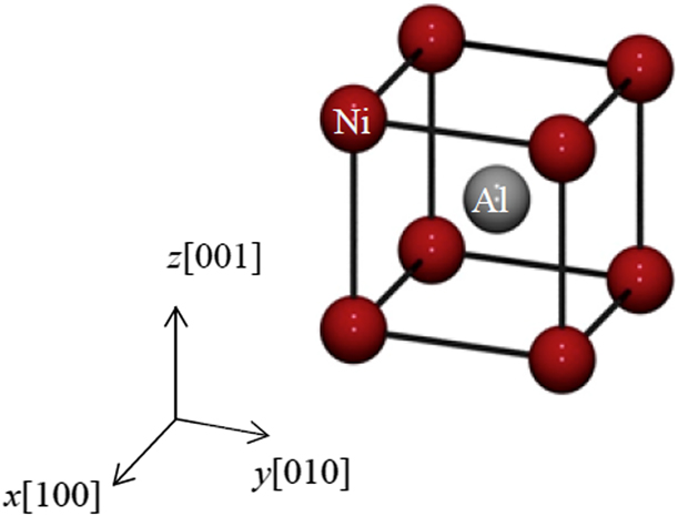
Figure 8: The B2 unit cell of Ni–Al alloy with 50% Ni composition.
Simulation settings
This study employed tight-binding (TB) potential to describe the interaction between Ni–Ni, Al–Al, and Ni–Al atoms with different parameters [Reference Cleri and Rosato28, Reference Rosato, Guillope and Legrand29]. The time step is 1 fs. In order to determine the phase transformation behavior, the cooling and heating process would be applied on the model under NTP ensemble with zero pressure. Other than adjusting the periodic length, the shape of periodic box could be flexibly changed into triclinic in order to make the shear stress zero. Instead of continuous heating and cooling process as commonly used in the literature [Reference Pun and Mishin8, Reference Uehara and Tamai11, Reference Ozgen and Adiguzel15, Reference Ozgen and Adiguzel16, Reference Uehara, Masago and Inoue18, Reference Uehara and Tamai19, Reference Uehara, Tamai and Ohno20], a quasistatic thermal process is implemented for each temperature. The model would be cooled from 1700 to 100 K and then heated back to 1700 K at 200 K temperature interval. For the starting temperature, 1700 K, of the cooling process, the initial model is constructed from B2 parent structure with 3.5 Å lattice constant. At each temperature, e.g., 1700 K, 1500 K, and 1300 K, the model would be simulated for at least 20,000 steps to make sure the equilibrium is reached and the equilibrated atomic positions are calculated by taking temporal average of the following 10,000 steps after reaching equilibrium. The equilibrated atomic positions are taken as the initial configuration for the next temperature simulation. The equilibrated length and angle of the model at each temperature will be recorded to identify the crystal structure. The reason for not taking the continuous thermal process is that the equivalent heating rate is extremely high (>109 K/s) and overcooling/overheating might appear to conceal the phase transformation process.
Only the 68% Ni–Al model would be subjected to loading test at low temperature and the shape recovery behavior at high temperature would be examined. For the loading process, the atomic model will first be equilibrated under NTP ensemble at 200 K with zero pressure while the periodic box remaining at cuboid shape. The loading is applied on equilibrated model at 200 K under NTV ensemble. In the loading process, the strain is applied incrementally and equilibrated at each loading step until reaching plasticity, at which the corresponding stress suddenly drops. Various loading conditions, e.g., uniaxial, biaxial, and shear, are tested separately at 1% strain increment. Once the models reach plasticity, the heating process will be imposed on the deformed model under NPT ensemble with zero pressure and shear stress. The model after heating up to high temperature will be inspected to determine whether the original shape is restored or not.
Acknowledgments
This research work is supported by Ministry of Science and Technology, Taiwan under the grant MOST 106-2923-E-006-004-MY3 and MOST 105-2628-E-006-003 -MY3.


 Open access