Introduction
In the soupy grist of a Ronchigram exist patterns a trained electron microscopist can use to immediately assess the quality of the instrument's alignment. By tuning the currents in a stack of electromagnetic lenses, the shape, texture, and symmetry of Ronchigrams may be sculpted until a large featureless region swims like a pool of spit (Figure 1). A well-placed aperture at the center of this pool creates an electron beam that can reveal atomic structure in vivid detail. The Ronchigram—its structure, etymology, and the physics that describes it—is puzzling to new microscopists yet requisite for high-resolution scanning transmission electron microscopy (STEM).
Figure 1: The patterns, shapes, and symmetries in an electron Ronchigram reveal lens aberrations and the quality of microscope alignment. (a) An experimental Ronchigram from an electron microscope is shown alongside (b) a simulated Ronchigram at 300 keV beam energy with a 65 mrad semi-angle aperture. Significant defocus adds structure near to the optic axis, while cumulative higher-order aberrations give rise to the six-fold shape typical of aberration-corrected electron microscopes.
Historical Development of the Ronchigram
The name Ronchigram honors the Italian physicist Vasco Ronchi (pronounced [ˈroŋki]), who in 1923 developed a standard test for shaping aberration-free light optical lenses [Reference Ronchi1,Reference Ronchi2]. In the eponymous “Ronchi test,” an optical lens focuses light onto a “Ronchi grating” comprised of alternating dark and clear stripes spaced ~100 × the light's wavelength (for example, 10–100 μm). Without this grating, the convergent beam appears as a uniform bright disc. However, with the Ronchi grating in place, the imperfections of the lens are revealed in the interference patterns (Figure 2). Shulz first used the term “Ronchigram” for light optical measurements in 1948 [Reference Schulz3].
Figure 2: Historical light Ronchigrams captured using Ronchi's linear grating technique initially developed in 1923 [Reference Ronchi1]. Interference fringes in (a) a perfect optical system are parallel, and in (b) an astigmatic system are serpentine. Reprinted with permission from [Reference Ronchi2], The Optical Society.
Constructing Ronchi's linear grating is not possible in an electron microscope because the diffracting wavelength is only a few picometers (for example, 2.51 pm at 200 keV). Instead, we use the atomic arrangement in amorphous materials to provide a nearly random assortment of atomic potentials—well approximated as a noisy grating (V noise(x)). This amorphous grating mimics the Ronchi test by providing interference patterns that reveal aberrations in electromagnetic lenses. From 1979, Cowley investigated the electron Ronchigram in the convergent beam electron diffraction (CBED) pattern, both coining the term electron Ronchigram [Reference Cowley4] and noting its benefit for measurement and correction of aberrations in STEM [Reference Cowley4–Reference Spence and Cowley8]. In conventional TEM the Ronchigram is not typically used for alignment because the electron beam is not converged on the sample [Reference Rodenburg and Macak9]. Today, the term Ronchigram is popularly associated with electron beams, while the light optics community more commonly refers to the “Ronchi test.”
A Portable Ronchigram Simulator
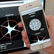
To promote an intuitive understanding of electron Ronchigrams, and how they are affected by aberrations, we developed the web application http://Ronchigram.com (Figure 3). This app calculates the electron Ronchigram of a thin amorphous sample—the same conditions used during a typical alignment. Through an intuitive graphical user interface, electron wavelength, objective aperture size, and up to 5th order aberrations can be specified or randomly generated.
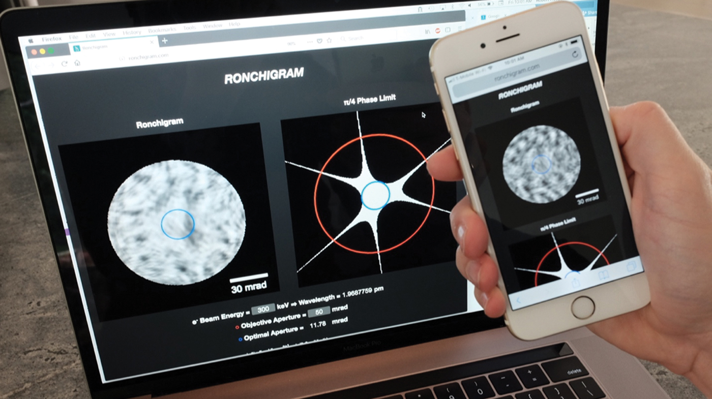
Figure 3: The Ronchigram.com web application allows exploration of Ronchigrams on any laptop computer or mobile phone. The blue circle visible in the Ronchigram on the phone indicates the maximum aperture size for the highest resolution achievable.
Concisely stated, the Ronchigram is the diffraction pattern of a convergent beam focused on an amorphous specimen. We calculate the Ronchigram from the probe wavefunction described by the Fourier transform of the aberration function transmitted through (that is, multiplied with) an amorphous specimen potential:  $\psi _t\lpar {\bi x} \rpar = FT\lcub {e^{-i\chi \lpar {\bi k} \rpar }} \rcub \; \cdot e^{-i\displaystyle{\pi \over 4}\cdot \sigma V_{noise}\lpar {\bi x} \rpar }$, where the lens aberration function, χ(k), is defined as:
 $$\chi \lpar {\alpha, \phi} \rpar = \displaystyle{{2\pi} \over \lambda} \mathop \sum \limits_{n,m\;} \displaystyle{{C_{n,m}\alpha ^{n + 1}\cos \lpar {m\lpar {\phi -\phi_{n,m}} \rpar } \rpar } \over {n + 1}}$$
 The terms C n,m and φ n,m describe a geometric aberration in Krivanek notation [Reference Krivanek10], m is the degree of the aberration, which for cylindrically symmetrical aberrations is zero and for asymmetric aberrations is defined by the smallest angle  $\displaystyle{{2\pi} \over m}$ such that the phase shift of the aberration is the same, n is the order of the aberration, λ is the wavelength of the electron beam, α is the convergence angle, and φ is the azimuthal angle. The popular Haider notation [Reference Haider11] is also provided on Ronchigram.com. To speed computation, we treat our specimen as a randomly generated noisy phase grating, which under the Eikonal approximation adds random phases to the electron beam $e^{-i\displaystyle{\pi \over 4}\sigma \cdot V_{noise}\lpar {\bi x} \rpar }$. Here, σ is the interaction parameter $\displaystyle{{2\pi m_ee\lambda} \over {h^2}}$ where m e is the relativistic electron mass and e is the charge of an electron, and Vnoise(x) provides random white noise values between 0 and $\sigma _{200\; keV}^{-1} $ with a cutoff frequency at kmax/2. Finally, the observed Ronchigram is the electron probability density on the diffraction plane and is equivalent to the square of the modulus of the Fourier transform of the transmitted wavefunction g(k) = |FT{ψ t(x)}|2.
Details Within the Ronchigram
Key features in the texture of a Ronchigram's fringes include magnification and symmetry. For an in-focus beam, the center of a Ronchigram has high local magnification that represents a coherent, nearly aberration-free portion of the beam (blue circle in Figure 3). Moving further from the optic axis (that is, the center of the pattern), aberrations reduce the local magnification. Asymmetric aberrations (m > 0) break rotational symmetry. When aligning a microscope, the operator tunes the currents through the electron lenses to minimize these aberrations.
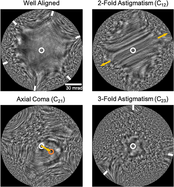
The presence of lower-order aberrations affects the structure and symmetry of the Ronchigram. Two-fold astigmatism (C12) unidirectionally stretches the region of high magnification and produces distinctive streaking, axial coma (C21) shifts the center of the Ronchigram, and three-fold astigmatism (C23) produces three-fold symmetric lobes (Figure 4). Experimentally, adjusting defocus can enhance the visibility of aberration symmetry. In a well-aligned aberration-corrected microscope, these lower-order aberrations can be nearly completely corrected, resulting in a large featureless region of high local magnification often with a characteristic six-fold structure attributable to residual higher-order aberrations [Reference Sawada12,Reference Kirkland13]. While these low-order aberrations can be recognized and corrected by hand, efficiently correcting higher-order aberrations necessitates the use of computer automation [Reference Delby14].
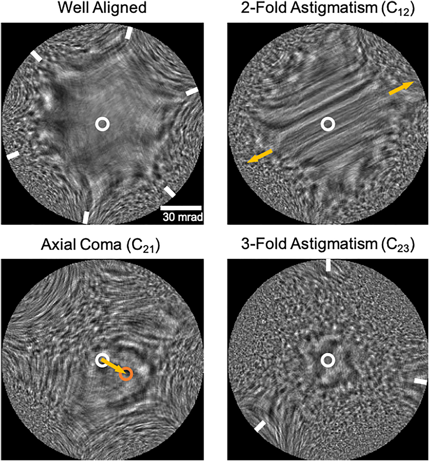
Figure 4: Simulated electron Ronchigrams visualizing common aberrations in aberration-corrected STEM. Simulations made with Ronchigram.com at 300 keV. The top-left image shows a well-aligned Ronchigram with minimal lower-order aberrations, giving rise to the large featureless region near the optic axis (white circle), while further from the optic axis residual higher order aberrations result in the six-fold structure (white tick marks). The top-right image has 10 nm of two-fold astigmatism (C12) and 10 nm of defocus (C10) applied, causing the region of high magnification to stretch and streaks to appear across its surface (gold arrows). The bottom-left image has 400 nm of axial coma (C21) and 15 nm of defocus applied, causing the center of the Ronchigram to shift (orange circle). The bottom-right image has 400 nm of three-fold astigmatism (C23) applied resulting in a three-fold structure (white tick marks).
Even after good alignment, aberrations will always become large far from the center of the Ronchigram, therefore portions of the beam that contain noticeable aberrations must be blocked by placement of a circular aperture. A larger permitted aperture size improves the diffraction-limited resolution. To optimize microscope imaging conditions, the aperture size must be balanced against the inclusion of aberrations. Aberrations refer to the phase shift of the electron wave at each position in the diffraction plane and should not exceed roughly  $ \pm \displaystyle{\pi \over 4}$ in order to achieve the best resolution and minimize probe tails [Reference Weyland and Muller15–Reference Krivanek17]. Along with an image of the Ronchigram, the $\displaystyle{\pi \over 4}$ phase limit (blue ring), optimal aperture size, and diffraction-limited resolution are displayed on Ronchigram.com (Figure 3).
Ronchigram.com
Interactive experimentation is the best way to build intuition for how aberrations are revealed in a Ronchigram. Ronchigram.com runs locally in a web browser using only client-side JavaScript including the Math.js package; no installation is required. It runs on any platform (for example, macOS, Windows, Linux), including your phone (for example, iOS, Android). Thus, mobile access provides an on-the-go solution for instant access to Ronchigrams—should an emergency arise. A simple interface streamlines calculation and facilitates fast adjustments to parameters. User-selection of the k-space sampling rate is supported, facilitating easy balancing between the desired Ronchigram resolution and computation speed. Fine adjustment of the feature size in the specimen potential structure (V noise(x)) is also supported. Ronchigram.com is an educational, open-source project released under the 3-clause BSD license, free for non-commercial use.
Significance
While information on all aberrations, including higher orders, is encoded in the Ronchigram, Cowley and his contemporaries could initially only use it to correct 1st and 2nd order aberrations, most notably, two-fold astigmatism and coma. The potential for multipole elements to negate the positive spherical aberration intrinsic to rotationally symmetric magnetic lenses had been known for a considerable time; however, only in the late 1990s was a multipole corrector system effectively realized, initiating the recent commercialization and the widespread implementation of aberration-corrected STEM imaging [Reference Krivanek10,Reference Scherzer18]. The Ronchigram has been essential to this corrector system, as well as subsequent systems, providing an easy and tractable measurement of the aberration state from which manual or automatic corrections could be made [Reference Krivanek10,Reference Sawada12,Reference Lupini and Pennycook19]. In the time since, aberration-correction has revolutionized scientific measurement, making sub-Angstrom resolution possible and the once obscure Ronchigram commonplace.
Conclusion
A Ronchigram simulator has been devised called Ronchigram.com. This software, free for non-commercial use, can assist in understanding Ronchigrams and thus helps in understanding the alignment of aberration-corrected scanning transmission electron microscopes.
Acknowledgment
Thanks to Ben Savitzky for feedback.