


Introduction
Advanced engineered materials enabled the lunar exploration era of the 20th century, and a new generation of materials will be required to facilitate human exploration of Mars and destinations beyond. For over two decades, synthesizing and processing materials at the nanoscale (<100 nm in one dimension) has attracted government, academic, and private attention enticed by the promise of unique properties, including large-surface area, high-aspect-ratio, and highly anisotropic and tailorable electrical and thermal conductivities, as well as unique optical properties. These properties can be applied to prepare high-strength, lightweight, and multifunctional structures; novel sensors; and energy-storage systems with highly reliable environmental control capable of radiation shielding. Despite the level of effort, aerospace adoption of engineered nanomaterials remains tepid, a reflection of both the immaturity of the materials and the qualification costs and certification standards required by the industry and its customers.
Applications of advanced materials in aerospace are as broad as the industry. Global aircraft production is an approximately USD$200 billion/year enterprise, comprising about half of the yearly sales in aerospace and defense.1 Of that, industry groups estimate that raw materials comprise USD$12 billion of the industry’s costs.Reference Zimm2 This can range all the way from bulk alloys of aluminum in the hundreds of millions of pounds to single-crystal nickel turbine blades. Research and development efforts in nanoscale materials match this application breadth. We have highlighted areas covering thermal protection, radiation protection, electronics and sensors, structural nanocomposites, and space propulsion. Reflecting their relative availability, many of the applications use carbon nanostructures (carbon nanotubes [CNTs] and graphene) and inorganic nanomaterials (silica and metal oxides).
Applications in aerospace
General
Engineered nanomaterials provide substantial improvements for structures and nonstructural components of almost all aeronautical and space systems. These include weight reduction; improved flexibility with maintained mechanical strength; multicomponent monitoring with redundant backup sensors; efficient power production, storage, and transmission; enhanced radiation protection for electronics and people; and sustainable life-support systems for long-duration exploration. We identify and highlight a few of the applications that are of interest to the aerospace and nanomaterials communities. Some of these applications are covered in further detail in the articles in this issue.
Propulsion
Rocket science would appear to be a natural starting point for the application of engineered nanomaterials, in particular, solid rocket motor propellant. Enhanced reactivity and faster burn rates can be achieved from the higher specific surface area provided by nanoscale particles. However, a balance must be achieved between increased reactivity with safe and predictive handling and storage of the material. Any advantages offered by nanoscale particles can be offset by application of coatings or surfactants to stabilize, disperse, or prevent aggregation, thereby reducing the propellant weight fraction. Increases in the reactivity and enhanced burn rates were found for nanoscale aluminum, but agglomeration and increased reactivity under storage conditions were highlighted.Reference DeLuca, Galfetti, Severini, Meda, Marra, Vorozhtsov, Sedoi and Babuk3 Evidence of hazards associated with this increased reactivity and the tendency for nanoparticles to agglomerate and thereby negatively affect performance were also reported.Reference DeLuca, Galfetti, Severini, Meda, Marra, Vorozhtsov, Sedoi and Babuk3 A rocket flight test using nanoscale aluminum particles and water ice fuel was achieved by The Pennsylvania State University and Purdue University in 2009.Reference Wood4–Reference Kittell, Pourpoint, Groven and Son7 Since then, efforts to optimize the performance and safety of these nanoengineered fuels have continued.Reference Wood, Pfeil, Pourpoint, Tsohas, Son, Connell, Risha and Yetter5 The use of nanoscale particles to improve the performance of the aluminum-water combustion reaction may enable an important driver for aerospace materials, in particular for long duration space flight: in situ resource utilization (ISRU). Harnessing resources en route enables mission architectures previously thought to be beyond both current resources and technology.
Thermal protection
Nanomaterials are now being incorporated into a variety of thermal protection materials to enhance the limits of thermal stability and mechanical integrity under a variety of aerothermal flow conditions. Research is also in progress to bring multifunctionality to unique task-specific material systems such as thermal protection systems (TPSs) used to protect spacecraft during the heat of reentering the atmosphere to providing protection from space radiation (Figure 1).

Figure 1. Carbon nanotubes in thermal protection materials before and after testing.Reference Nikolaev, Sosa, Arepalli, Coughlin, Moloney, Boul, Fowler, Yowell, Christiansen, Davis, Arnold, Stackpoole, Fan, Boghozian, Thornton, Johnson, Chavez and Olson8 (a) Single-walled carbon nanotubes coated with phenolic polymer. (b) Nano-PICA (phenolic-impregnated carbon ablator) after arc-jet testing and hypervelocity micrometeoroid impact to simulate atmospheric entry conditions. A thick char layer has formed.
CNTs were incorporated into the unique TPS system, phenolic-impregnated carbon ablator (PICA), to improve its char strength and protection from micrometeoroid impacts.Reference Nikolaev, Sosa, Arepalli, Coughlin, Moloney, Boul, Fowler, Yowell, Christiansen, Davis, Arnold, Stackpoole, Fan, Boghozian, Thornton, Johnson, Chavez and Olson8 It was expected that CNTs would increase the char strength by adding an additional fibrous structure to the otherwise randomly orientated pyrolysis region. Bulk performance characterized by standard TPS test methods showed considerable improvement to mechanical resiliency under ablative conditions compared with standard PICA material (Figure 2).

Figure 2. Heating characteristics of composites with (a) various loadings of pristine multi-walled carbon nanotubes (MWCNTs) in SMP-10 (liquid precursor to silicon carbide ceramics; “control”) and (b) 0.75 wt% of each MWCNTs, raw single-walled CNTs (r-SWCNTs), functionalized SWCNTs (f-MWCNTs), and purified SWCNTs (p-SWCNTs) in SMP-10 at 30–40 W directed microwave power.Reference Higginbotham, Moloney, Waid, Duque, Kittrell, Schmidt, Stephenson, Arepalli, Yowell and Tour10
In situ resource utilization
Human space exploration beyond the relative convenience of orbital operations necessitates the need for astronauts to repair rather than replace. Materials processing and repair in remote locations will be extremely challenging, limited by available power and raw materials. This fact further supports the need for ISRU.
In one study, Imholt et al.Reference Imholt, Dyke, Hasslacher, Perez, Price, Roberts, Scott, Wadhawan, Ye and Tour9–Reference Higginbotham, Stephenson, Smith, Killips, Kempel and Tour11 observed efficient conversion of microwave radiation into heat. Driven, in part, by improvements sought after the Shuttle Columbia disaster, NASA Johnson Space Center and Rice University successfully integrated multiwalled carbon nanotubes in low weight percentages into pre-ceramic materials used for repair of reinforced carbon–carbon thermal protection materials critical for spacecraft reentry. The repair material system centered around a customized commercial pre-ceramic polysilylene-methylene copolymer that converts into a silicon carbide ceramic at high temperatures (∼850–1200°C). Very low power levels (30–40 W) of microwave energy achieved bulk cure temperatures of 1150°C in 7 min.Reference Imholt, Dyke, Hasslacher, Perez, Price, Roberts, Scott, Wadhawan, Ye and Tour9
Future systems envisioned could be either ceramic or polymeric materials with CNT inclusions that could be processed at desired temperatures using low-power microwave radiation. This technique could also be applied to the processing of materials excavated from planetary surfaces for ISRU.
The commercial airline industry also places enormous emphasis on quality assurance and repairability of structures and materials. New nano-enhanced materials will have difficulty passing the required US Federal Aviation Administration or similar certification without appropriate avenues for repair and maintenance. Public and private funding for qualification, testing, and certification of materials for use in commercial aerospace applications in general is sorely lacking, receiving only initial funding and attention from government research agencies, such as the European Union’s Horizon 2020 Funding,12 but there is no evidence yet of large-scale industry adoption in the commercial arena.
Life support
Technologies for life support or environmental control and life support systems (ECLSS) represent a fertile ground for nanoengineered materials, with the greatest challenges presented by long-duration human space exploration. Whether for short-duration missions within the relative safety of low Earth orbit (LEO) or proposed long-duration missions such as ones to Mars, reliable supplies of air, water, and food; systems for waste management; and functional habitable space are required. LEO operations, including those on the International Space Station, have provided a useful proving ground for ECLSS technologies, and as spacefaring nations prepare for long-duration missions to destinations such as Mars, testing technologies in LEO is considered a requirement.
As such, no flying ECLSS currently utilize nanomaterials, but the relatively poor reliability and performance of current ECLSS warrants adoption of high-surface-area and conductive nanomaterials as one route to improve overall system performance. CNTs have been functionalized with secondary amines to achieve CO2 removal, an indispensable ECLSS function, and to address the limitations of current systems, including regenerability and high power consumption.Reference Moloney, Huffman, Gorelik, Nikolaev, Arepalli, Allada, Springer, Yowell, Benson, Chipara, Edwards and Phillips13,Reference Allada, Moloney, Anderson, Smith, Arepalli, Yowell, Chattopadhyay, Shah, Billups and Filburn14 Water purification and recovery is challenging under the best of conditions, but the addition of a microgravity environment and the necessity of multiyear robustness have driven several examples of water filtration systems based on nanomaterials. Carbon fullerenes have shown promise in the purification of water,Reference Pickering and Wiesner15 and NASA-sponsored nanoscale filtration technology using CNTs was developed into a commercial product.16 Although questions remain about scalability, perforated graphene is an actively researched material for water filtration, attracting significant aerospace and defense investmentReference Wang and Karnik17–Reference Aghigh, Alizadeh, Wong, Islam, Amin and Zaman19 (see Figure 3).

Figure 3. (a) Nanoporous graphene water desalination (simulation and schematic), (b) schematic of nanopores with hydrophilic bonding, (c) graphene filter computer simulation, and (d) nanopores with hydrophilic bondings (left) and functionalized nanopores on graphene (right).Reference Aghigh, Alizadeh, Wong, Islam, Amin and Zaman19
Although the specialist nature and limited market for ECLSS technologies does not attract large-scale dedicated investment, the challenges of providing clean water and air to large segments of the world’s population provides the necessary “dual use” to attract both academic and government interest.
Power and energy
Aeronautical and space systems need reliable power production, storage, and transmission for both short- and long-duration activities. Existing energy systems are being replaced or supplemented with nanomaterial-enabled innovations. Silicon-based solar cells with improved efficiencies and lifetimes have been developed. Better-engineered materials based on graphene and perovskites are undergoing continuous improvement.
Various different nanostructures have been developed over the past half century from silicon to multijunction solar cells, with increasing efficiency and robustness.24 Work is also in progress to improve other concepts for energy generation, including piezoelectric generators based on ZnO and other materials.Reference Jing, Xie, Zhu, Han and Wang33 The performance of a variety of fuel cells has been improved dramatically with the incorporation of engineered nanomaterials in all components, including electrodes, electrolytes, and ion-exchange, and gas-diffusion membranes.Reference Huang, Zhao, Cao, Chen, Zhu, Lin, Li, Yan, Zettl, Wang, Duan, Mueller and Huang20 A new class of low-cost metal-free catalysts based on CNTs with added nitrogen was developed and found to perform better than platinum in basic fuel cells. The latest research demonstrates the use of carbon-based metal-free catalysts in acidic fuel cells, including carbon composites with a porous structure to increase surface area and nanotubes to enhance conductivity, which could soon facilitate the commercialization of affordable and durable fuel cells for aerospace applications.Reference Dai, Xue, Qu, Choi and Baek21
In 1958, the Vanguard I satellite used a small (<1 W) silicon solar cell array to power its radios. Later that year, Explorer III, Vanguard II, and Sputnik-3 were launched with photovoltaic-powered systems on board. In 1964, NASA launched the first Nimbus spacecraft, a satellite powered by a 470 W photovoltaic array, and in 2000, at the International Space Station, astronauts began installing solar panels on what became the largest solar power array deployed in space. Each “wing” of the array consists of 32,800 solar cells (Figure 4).

Figure 4. Solar cells on the International Space Station. Source: NASA Space Exploration Image Gallery.
According to a 2014 report, the Deployable Space Systems of California developed a flexible solar array design that can unfurl in space to generate spacecraft power supplies and then retract for delicate maneuvers and docking to other spacecraft. The Roll Out Solar Array (ROSA) system features a “roll out” design that uses carbon fiber composite booms to deploy solar panels without the aid of motors, making it lighter and less expensive than current solar array designs.22
New combinations of nanomaterials and three-dimensional morphologies, to capture incoming photons of the entire solar spectrum from deep ultraviolet to far-infrared for photovoltaic and thermovoltaic conversion, as well as innovations to multiply the number of electrons released per photon, will enhance solar-cell performance tremendously.Reference Savin, Repo, von Gastrow, Ortega, Calle, Garín and Alcubilla23,24 The combination of high-performance polymers with nanoparticles holds the promise of further increasing the efficiency of flexible solar cells, especially for space applications.
Conventional energy storage using batteries is now being replaced with hybrid systems of rechargeable batteries and supercapacitors to provide the highest possible specific energies and power densities to reduce the volume and weight of these systems. The efficiencies of batteries and supercapacitors have been improved dramatically over the past few years through the use of engineered nanomaterials, including carbon as well as other materials. Early work on CNT-based supercapacitors was summarized in a review article in 2005.Reference Arepalli, Fireman, Moloney, Nikolaev, Yowell, Higgins, Kim, Kohl, Turano and Ready25 Recent work involving control of porosity and surface area has improved the supercapacitor performance multifoldReference Pandey, Maiti, Palanisamy, Nikolaev and Arepalli26 (Figure 5).

Figure 5. Supercapacitor performance using (a) pristine and ultrasonicated (U) double-walled carbon nanotubes (DWCNTs), respectively.Reference Pandey, Maiti, Palanisamy, Nikolaev and Arepalli26 (b) CV curve at different scan rates, and (c) specific capacitance dependence on current density for hierarchically porous graphitic (HPG) carbon and different samples of activated carbon (AC-1 and AC-2).Reference To, Chen, Yao, He, Kim, Chou, Pan, Wilcox, Cui and Bao28
Recently, NASA’s Space Technology Mission Directorate selected “high energy density and long-life Li–S batteries” as one of four proposals for future energy-storage system development.Reference Bugga, Jones, Pasalic, Addison and Thiallaiyan27 A recent study highlighted a “designer carbon” prepared from a hydrogel polymer with controlled porosity and high surface area, resulting in astonishing battery and supercapacitor performance.Reference To, Chen, Yao, He, Kim, Chou, Pan, Wilcox, Cui and Bao28
In the area of energy transmission, copper wires inside space vehicles and structures can be replaced by lightweight conducting wires made of CNTs.Reference Wang, Behabtu, Young, Tsentalovich, Pasquali and Kono29 The Japanese space agency (JAXA) recently tested wireless energy transmission by microwaves.Reference Yoshida, Hasegawa and Kawasaki30 JAXA is planning to test the technology in space by 2018, with a small satellite transmitting several kilowatt from LEO to a microwave receiver on the ground. JAXA hopes to have a 100 kW satellite in orbit by 2021 and a 200 MW version by 2028. By 2031, a proposed 1 GW commercial pilot plant could be in operation, with a full commercial space-based power industry to kick off with one launch per year starting in 2037.Reference Sasaki31
In this issue
In this issue, Meador provides a succinct overview of the potential of nanotechnology to benefit aerospace, as well as the technical barriers preventing wider-scale adoption in the field. He notes the significant advances made over almost two decades of progress, while highlighting challenges such as synthesizing nanomaterials at scale and integration methods that preserve the properties and performance noted at the nanoscale toward bulk implementation. Meyyappan et al. review research and engineering progress made toward nanomaterials-enabled electronics and high-performance sensors whose small footprint, low power consumption, and radiation hardness make them highly suitable for space applications.
Recent advances made using CNTs toward fulfilling the two decade promise of superlightweight structural materials have rejuvenated hope of system-level benefits. Siochi and Harrison describe these advancements, along with remaining challenges. Thibeault et al.’s topic of materials for space radiation shielding is a prominent example of where the aerospace industry, and its various funding centers, will need to lead. Nanomaterials are seen as having great potential toward multifunctional materials solutions for protection from galactic cosmic radiation and solar particle events with their respective mix of high-energy protons and atomic nuclei.
In their article, Lozano et al. present a novel nanomaterial- and microelectromechanical-systems-enabled solution for ionic-liquid thrusters, in the realm of electric propulsion for space. Practical manufacturing schemes of nanoengineered materials are suggested for the implementation of microfabricated and nanostructured thruster arrays. The article by Puneet et al. covers an interesting area of controlled CNT architectures for thermal management applications in aerospace. They have identified a possible roll-to-roll nanomanufacturing process for energy-storage devices for aircraft. Finally, in the accompanying sidebars, Suraj Rawal and Jud Ready, respectively, highlight the pioneering integration of nanomaterials for electrostatic discharge applications on the Juno spacecraft that provided cost and schedule savings over traditional solutions, as well as other space missions incorporating interesting applications of nanomaterials in space and exploration programs.
Opportunities and challenges
Unlike other historical materials innovations catalyzed by aerospace and defense, such as carbon-fiber-reinforced polymers, innovation in nanomaterials is a global concern, with other commercial applications, such as medicine and energy, driving advancements. Nanotechnology leaders in the aerospace community have noted that for the industry to both drive and utilize nanomaterials, a new level of partnership among commercial, scientific, systems, and production engineering players is crucial.Reference Vaia32 Funding from government sources such as defense science and technology programs, at least in the European and US context, is no longer the preeminent driver of advanced materials. The expectation that commercial and defense contractor internal research and development will be harnessed toward the development and integration of nanomaterials for aerospace uses is somewhat unrealistic. There is significant cost and risk in maturing advanced materials synthesis, processing, and application into a well-understood material, one produced at scale and at a price the market will adopt.
One potential solution to reducing development costs highlighted by Meador is innovative “materials-genome”-level modeling and simulation in concert with experimental testing and characterization methods that could reduce development and qualification costs. It is hoped that this modeling work will also assist in crossing the length scales of nanoengineered materials (i.e., more accurately translating modeled and experimentally verified performance into reality at the macroscale).
For the global aerospace industry to keep pace with, let alone lead, other commercial sectors in the adoption of nanoengineered materials, targeted and meaningful funding from sources that can accept the risk for the prospect of long-term potential benefits will still remain, for the most part, government-sponsored aerospace science and technology programs.
Juno and carbon nanotube technology
Advances in the synthesis, processing, and characterization of thin carbon nanotube (CNT) sheets and carbon nanostructures (CNSs) grown on carbon fibers offers a unique opportunity to exploit the multifunctional property attributes of these materials for spacecraft components. Ongoing research and development efforts indicate that state-of-the-art CNT-based films, coatings, and sheets could readily provide effective electromagnetic interference shielding and electrostatic dissipation (ESD).Reference Rice, Gibson and Lafdi1 It was recognized that the use of CNT sheet-based composites with a state-of-the-art composite manufacturing process offered cost and schedule savings by eliminating labor-intensive surface preparation steps for composite surfaces, such as scuffing to expose conductive carbon fibers, applying an electrically conductive coating or film, or bonding with an aluminum foil to satisfy ESD requirements. In collaboration with Juno spacecraft engineers, the following three components (as secondary structures) were designed and fabricated using carbon nanotechnology:Reference Rawal, Brantley and Karabudak2
(1) A CNT sheet (from Nanocomp Technologies, Inc.) co-cured as an outer ply on M55J/cyanate ester (carbon fiber/CE) composite tubes satisfied the ESD requirements. Four such tubes were designed and fabricated and used as four rocket engine motor (REM) support struts.
(2) A CNT/CE sheet prepreg was processed and used as an outer ply of the layup of an M55J/CE composite sandwich panel. Two engine cover panels (one for flight and one spare) were successfully processed.
(3) IM7 (carbon fiber) plain-weave fabric with integrally grown CNSs was produced by Lockheed Martin. Using this fabric, an IM7 (CNS)/BTCy-1 (carbon fiber/resin) prepreg was processed to fabricate composite laminates in a saddle configuration. These were used as a support structure for the multilayer insulation held around the linear actuator used for solar array deployment (labeled as a linear actuator multilayer insulation support [LAMLIS] structure).
Each of the CNT-based REM support struts, the engine cover panels, and the IM7 (CNS)-based LAMLIS structure (Figure 1) were subjected to component-level and system-level tests. Each part satisfied the mechanical and ESD requirements. Finally, the CNT-based REM support struts, the engine cover panels, and the IM7 (CNS)-based LAMLIS structure were flown on the Juno spacecraft, which was launched successfully on August 5, 2011.
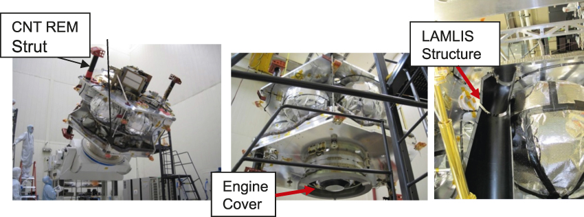
Figure 1. Carbon nanotube- (CNT-) based composite rocket engine motor (REM) struts and engine cover panel and carbon nanostructure-based composite linear actuator multilayer insulation support (LAMLIS) structure incorporated in the Juno spacecraft inherently provide electrostatic dissipation protection.
Successful use of CNT technology in the Juno spacecraft was labeled as a pathfinder for similar future applications in which the benefits of carbon nanotechnology can be fully utilized. Future advances in processing and manufacturing technologies are anticipated to yield continuous CNT yarns (like carbon fiber) and graphene ribbons and sheets to help translate the multifunctional properties of nanoscale carbon into macroscale composites with minimum loss of nanoscale properties in the design and manufacture of lightweight structures.
ALICE
Launched from Vandenburg Air Force Base, (Lompoc, Calif.) on December 5, 2013, the CubeSat ALICE (Figure 1) was designed by the Air Force Institute of Technology (AFIT) and inserted into low-Earth-orbit (LEO) to test an integrated miniaturized electrostatic analyzer (iMESA) measuring the electron output current from a carbon nanotube (CNT) experiment (Figure 2) designed by Georgia Tech. ALICE is a 3U CubeSat (consisting of three units with dimensions 10 × 10 × 10 cm each), whose name is an acronym for AFIT LEO iMESA CNT Experiment. ALICE was designed and built by AFIT with the objective of testing the performance of a pair of advanced CNT arrays for a potential propulsion system for nanosatellites. ALICE directly exposes one ∼1 cm2 CNT array to the space environment while protecting an identical control array within the satellite. The payload experiment utilizes the iMESA sensor device, designed by the US Air Force Academy in Colorado Springs, Col. It couples a series of microchanneled plates that provide a tortuous and variable electron path that allows the team to measure the number and speed of electrons emitted by the field effect from the CNT arrays.

Figure 1. The 3U CubeSat ALICE includes communication antennas and experimental modules atop an Attitude Determination and Control System (ADCS) mounted to the spacecraft “bus” that is powered by deployed solar-cell arrays.

Figure 2. The payload consists of (upper left) a silicon wafer fabricated with thousands of carbon nanotube (CNT) electron emitters; (images right) a ∼1 cm2 chip is wire bonded to a package that is then mounted (lower left) to the iMESA sensor arrays.
Researchers at the Georgia Tech Research Institute produced the CNT arrays of vertically aligned nanotubes embedded in silicon chips as Spindt-style emitters.Reference Spindt1 Existing ion thrusters rely on thermionic cathodes, which use high temperatures generated by electrical current to produce electrons. These devices require significant amounts of electricity to generate the heat and must consume a portion of the propellant to prevent thermal runaway in their operation. If, instead, the CNT arrays could be used as electron emitters, they would operate at lower temperatures with less power—and without using the limited on-board propellant. That could allow longer mission times for satellites or reduce the weight of the micropropulsion systems. The orbit of the ALICE CubeSat will decay in 2035. At the time of this writing, communication issues are hindering data retrieval of current space craft status.
RAVAN
Scheduled for launch in summer 2016, RAVAN (Radiometer Assessment using Vertically Aligned Nanotubes) is a 3U CubeSat (Figure 3) mission led by the Johns Hopkins Applied Physics Laboratory (APL), to demonstrate technology needed to measure the absolute imbalance in the Earth’s radiation budget across the entire spectrum of energy—from the ultraviolet to the far-infrared—for the first time. Under stable climate conditions, the energy from the sun reaching the top of Earth’s atmosphere and that being reflected or radiated to space are equal. However, there is substantial evidence that even a <1% difference can lead to dramatic climate shifts. RAVAN will demonstrate how Earth’s radiation imbalance can be unambiguously and affordably quantified from space, enabling a huge leap in the ability to predict the future climate.

Figure 3. Blue Canyon Technologies has been awarded a contract to build, test, and operate Radiometer Assessment using Vertically Aligned Nanotubes (RAVAN), which will be built based on their XB1 triple (3U) CubeSat bus.
RAVAN will use a small, extremely accurate radiometer, with a “forest” of CNTs grown at APL that serves as the radiometer’s light absorber. The CNTs are a very deep black across the energy spectrum, which will let the radiometer gather virtually all of the light reflected and emitted from the planet.
LISA
Scheduled for launch in November 2015,2 the European Space Agency’s LISA (Laser Interferometer Space Antenna–Figure 4) Pathfinder Space Technology 7 (ST7) mission (formerly called SMART-2) will test in flight the concept of low-frequency gravitational wave detection (Figure 5). Albert Einstein predicted the existence of gravitational waves—ripples in space time—in 1915, occurring as a result of events such as closely orbiting binary star systems, black hole mergers, and the aftermath of the Big Bang. To measure gravity waves, a satellite must be in a completely noise-free environment—even the solar pressure from the Sun must be eliminated.

Figure 4. The Laser Interferometer Space Antenna (LISA) Pathfinder (left) will be launched by a VEGA rocket from Kourou, French Guiana, and will be placed into a slightly elliptical parking orbit. From there, it will use its own propulsion module (right) to reach its final operational orbit.

Figure 5. The Laser Interferometer Space Antenna (LISA) Technology Package (LTP) uses sensitive interferometry to gauge the relative motion of test masses. The LTP is stabilized by field-effect electric propulsion microthrusters that counter solar pressure, which would disrupt the exquisite accuracy required of the measurements.
ST7 will put two test masses in a near-perfect gravitational free fall and control and measure their motion with unprecedented accuracy. To do this, it will use inertial sensors, a laser metrology system, a drag-free control system, and an ultraprecise micropropulsion system. The disturbance reduction system (DRS) will demonstrate that a solid body can float freely in space completely undisturbed. Ideally, the two test masses will follow a trajectory determined only by the local gravitational field. The spacecraft position must be continuously adjusted to stay centered about the test masses. In this way, the spacecraft essentially flies in formation with the test masses.
The ST7 DRS consists of clusters of micronewton thrusters that use sensor information to control actuation and thus keep the test masses completely isolated from external forces. These electrospray thrusters require a precision on the order of 100 nN to counteract the small disturbance forces in a very precise manner. The spacecraft therefore utilizes a CNT-based electron emitter from Busek Co. Inc. (Natick, Mass.) to serve as a low-power neutralizer for the electrospray thrusters.
Acknowledgments
The authors thank Suraj Rawal and Jud Ready for their sidebar contributions to this article.


