

I. SUBPIXEL ARRANGEMENTS IN LCD
A single pixel on a color liquid crystal display (LCD) contains several individual color primaries, typically three color elements ordered (on various displays) either as blue, green, and red (BGR), or as red, green, and blue (RGB).Footnote 1 Some displays may have more than three primaries, often called multi-primary, such as the combination of red, green, blue, and yellow (RGBY), or red, green, blue, and white (RGBW), or even red, green, blue, yellow, and cyan (RGBYC) [Reference Messing, Kerofsky and Daly1]. These color primaries, sometimes called subpixels, are fused together to appear as a single color to human due to the blurring by the optics and spatial integration by nerve cells in the human eyes. Methods that take the interaction between display technology and human visual system (HVS) into account are called subpixel rendering algorithms [2,Reference Gibson3]. Subpixel rendering technology is well suited to LCDs, where each (logical) pixel corresponds directly to three or more independent color subpixels, but less so for cathode ray tube (CRT). This is because in a CRT the light from the pixel components often spreads across pixels, and the outputs of adjacent pixels are not perfectly independent (see footnote 1).
About 20 years ago, the Apple II personal computer Introduced a proprietary high-resolution LCD graphics display, in which each pixel has two vertical stripe subpixels with green and magenta colors, respectively. Without subpixel technology, a diagonal white line on Apple II display could only be drawn using “whole” white pixels composed of a paired green and purple subpixels, as shown in Fig. 1(a) [Reference Gibson3]. Thanks to Apple's built-in subpixel technology, white pixels are often composed of adjacent subpixels to yield a much smoother result, as shown in Fig. 1(d).

Fig. 1. Rendering of a sloping edge on Apple II display. (a) pixel-based rendering result, (b) pixel-based rendering (actual color pattern), (c) subpixel rendering (actual color pattern), (d) subpixel rendering (conceptual) result.
Similar situation exists for modern-day RGB vertical stripe LCD panels. Figure 2 shows a common problem when a sloping edge is displayed by pixel rendering, and how it can be suppressed by subpixel rendering. Simple pixel-based rendering causes sawtooth in the sloping edge in Fig. 2(a). Thanks to the fact that a pixel is composed of three separable subpixels, we can “borrow” subpixels from adjacent whole pixels. Figure 2(b) depicts that using subpixel rendering, the apparent position of the sloping edge is micro-shifted by a one or two subpixel width, giving a much smoother result compared to Fig. 2(a). However, subpixel rendering may cause local color imbalance called “color fringing artifact” [Reference Gibson3–Reference Klompenhouwer, De Haan and Beuker5], because for some pixels, only one or two subpixels are turned on/off, as shown in Fig. 2(c).

Fig. 2. Rendering of a sloping edge on RGB vertical stripe display. (a) pixel-based rendering, (b) subpixel rendering (conceptual) result, (c) subpixel rendering (actual color pattern).
Although the components of the pixels (primary colors: RGB) in an image sensor or display can be ordered in different patterns or pixel geometry, the geometrical arrangement of the primary colors within a pixel can be varied depending on the usage. In computer monitors such as LCDs that are mostly used to display edges or rectangles, the companies would typically arrange the subpixel components in vertical stripes. However, in displays for motion pictures, companies would tend to arrange the components to have delta (or triangular) or other two dimensional (2D) patterns so that the image variation is perceived better by the viewer.
In 2000, Clairvoyante developed the “PenTile” matrix as a new approach to build and drive color flat panel displays [Reference Elliot and Higgins6,Reference Credelle, Elliott and Higgins7]. The PenTile design takes advantage of the way the human eye and brain process visual information and optimizes the pixel layout to match this process. Various subpixel layouts have been proposed by Clairvoyante/Nouvoyance (and demonstrated by Samsung) as members of the PenTile matrix family [Reference Elliot and Higgins6,Reference Credelle, Elliott and Higgins7]. Illustrated in Fig. 3 are a conventional RGB vertical stripe subpixel arrangement and higher-efficiency PenTile RGBTM (RGBG), PenTile RGBWTM subpixel arrangements.

Fig. 3. (a) Conventional RGB Stripe arrangement, (b) PenTile RGB subpixel arrangement utilizing 33% fewer subpixels, (c) PenTile RGBW subpixel arrangement utilizing 33% fewer subpixels.
PenTile RGBG layout uses green pixels interleaved with alternating red and blue pixels, due to the fact that the human eye is most sensitive to green, especially for high-resolution luminance information. As a result, the RGBG scheme creates a color display with one third fewer subpixels than the traditional RGB–RGB scheme but with the same measured luminance display resolution. The PenTile RGBG offers improvements in cost performance and power efficiency compared to conventional RGB stripe display, due to the combined effect of increased aperture ratio in LCD devices or decreased current density in Organic light-emitting (OLED) devices. And it has been widely used in various phones, such as the Google/HTC Nexus One Android phone, Samsung i9000 Galaxy S phone, Samsung Wave S8500 series phones as well as the newly released Galaxy Nexus phone.
In PenTile RGBW layout, one pixel contains two subpixels only and every two consecutive pixels would have these four subpixels: red, green, blue, and white. For any two consecutive rows, the color pattern of the second row is shifted to the right by 1 pixel location. Thus, all the subpixels in PenTile RGBW appear to have delta configuration, which should be good for displaying edges in many orientations. Displays made using the PenTile RGBWTM pattern offer improvements in cost performance and power efficiency compared to conventional RGB stripe displays, due to the combined effect of increased aperture ratio and improved light transmission through the white (clear) subpixel. Note that Motorola Atrix 4G phone uses PenTile RGBWTM pixel geometry display.
VP (visual perception) dynamics is another company working on displays with special dedicated subpixel rendering technologies. They have two major products: VPX and VPW [8,9]. In their VPX LCD panel, they modify the regular RGB stripe pixel geometry by shifting every other line to the right by one subpixel location, as shown in Fig. 4(c), making it similar to the delta configuration. With this modification, the VPX LCD panel combined with a subpixel rendering driver can achieve three times (3×) higher horizontal resolution than the regular RGB stripe LCD panel. As they only change the arrangement of the color filter for the subpixels, the VPX panel can be manufactured with essentially the same process as regular LCD. In their VPW panel, they modified the LCD panel such that a regular RGB stripe pixel with three subpixels (RGB) is replaced by a VPW pixel with 4 square-shaped subpixels corresponding to red, green, blue and white color (RGBW), as shown in Fig. 4(d). The main advantage of VPW (RGBW) technology is four times (4×) higher resolution (2× horizontal resolution and 2× vertical resolution) and lower power consumption. As the shapes of the VPW subpixels are different from the regular RGB stripe LCD, VPW manufacturing probably requires more modification than VPX.

Fig. 4. Pixel geometry of (a) RGB vertical stripe display, (b) RGB delta, (c) VPX (with 3 subpixel/pixel), and (d) VPW (with 4 subpixel/pixel).
II. SUBPIXEL-BASED SPATIAL-DOMAIN ALGORITHM DESIGN
A) Subpixel rendering for font image
Subpixel rendering techniques originate from the problem of monochrome font rendering on LCDs. Previously, simple pixel-based font display was used and the smallest level of detail that a computer could display on an LCD was a single pixel. However, researchers found that, by controlling the subpixel values of neighboring pixels, the number of points that may be independently addressed to reconstruct the image is increased, and it is possible to micro-shift the apparent position or orientation of a line (such as the edge of a font), by one or two subpixel width, to achieve better edge reconstruction [Reference Platt10,Reference Betrisey11].
In 1998, Microsoft announced a subpixel-based font display technology called “ClearType” [2]. Note that Microsoft ClearType is software-only subpixel technique capable of improving the readability of text on regular LCD with three vertical stripe subpixels (red, green, and blue), which requires no change of display hardware. With ClearType running on an LCD monitor, features of text as small as a fraction of a pixel in width can be displayed. Figure 5 illustrates an example of displaying the letter “m” with traditional pixel rendering and ClearType [2]. It is obvious that ClearType can reduce staircase artifacts effectively and reconstruct the shape information more faithfully. Microsoft ClearType is especially suitable when rendering relatively small-size font, and the width of consecutive font size probably differs by subpixel only.

Fig. 5. (1) Letter “m” in italic, (2) whole-pixel rendered “m” with jagged edges, (3) subpixel rendered “m” with smooth edges.
While subpixel rendering may cause local color imbalance (color fringing artifacts), Microsoft ClearType suppresses color artifacts via “energy sharing”, where each subpixel's “energy” spreads across it and its two neighboring subpixels by turning on such subpixel and its two immediately adjacent neighbors each with 1/3. Hence, the energy of a single subpixel is shared with its two neighbors instead of putting all the energy entirely within it [Reference Platt10,Reference Betrisey11]. Such energy sharing always turns on a set of R–G–B (or G–B–R or B–R–G) subpixels by the same amount.
One negative side effect of this “energy sharing” is blurring artifact, which is caused by the neighboring subpixels having a little too much energy compared with the primary center subpixel. Gibson [Reference Gibson3] proposed to simply repeat the filtering process again by having each of the three first-stage recipient subpixels share the energy with their three neighbors. Since two sets of division by three are performed, the resulting intensity has the energy distribution that equals to spread the original subpixel's energy out across the closest five subpixels using a five element inter-color low-pass filter with [1/9, 2/9, 3/9, 2/9, 1/9] coefficients [Reference Gibson3]. The five coefficients of low-pass filter sum to 1, indicating that the total energy of the original center subpixel is fully represented by the spread of five subpixels. Due to relatively higher value of the center coefficient than neighbors, the majority of the energy is kept in the center of the spread. Note that both ClearType's inter-color three-tap filter or Gibson's inter-color five-tap filter relieve color fringing artifact by spreading the energy of one subpixel to three or five subpixels, thus the R, G, B values within any pixel tend to be very similar, if not identical, making the resulting image appear monochrome.
B) Subpixel rendering for color image downsampling
Subpixel rendering is especially important for small size portable devices such as digital camera and smart phone (which may have relatively low-resolution screen). Currently, available portable devices are capable of capturing images with multiple mega-pixel resolution. And high resolution displays are becoming more and more popular in high-end smart phones and are indeed very attractive to consumers. Nevertheless, we note that there are still many mid- or entry-level portable devices with relatively low-resolution display such as the HTC Wildfire S (launched in 2011), which is quite common among university students here in Asia. HTC Wildfire S sells for about USD250 each and has a 480 × 320 display with 153 600 pixels and a 5 mega pixel camera. Therefore, we find that it is very meaningful to use subpixel rendering techniques to achieve higher apparent resolution when displaying high-resolution image/video on relatively low-resolution portable devices. For simplicity, we assume that an input high-resolution image L (meaning large) of size 3M × 3N is to be down-sampled to a low-resolution image S (meaning small) of size M × N, and to be displayed on a M × N device. (Note that if L is not of size 3M × 3N, i.e. the downsampling ratio is not 3, we can use regular interpolation or decimation methods to resize L to be 3M × 3N).
A simple way, called direct pixel-based downsampling (DPD) in this paper, is to perform simple downsampling by selecting one out of every N pixels. (In this paper, the term Direct means no anti-aliasing filter is applied.) It can incur severe aliasing artifacts in regions with high-spatial frequency (such as staircase artifacts and broken lines as shown in Fig. 6(b)). An improved scheme is called pixel-based downsampling with anti-aliasing filter (PDAF) in which an anti-aliasing filter is applied before DPD. It suppresses aliasing artifacts at the price of blurring the image, as only the low-frequency information can be retained in the process [Reference Gonzalez and Richard12]. Note that both DPD and PDAF are pixel-based methods and do not incur color artifacts.

Fig. 6. (a) Direct Pixel-based Downsampling (DPD), (b) magnified result of DPD, where “grass” is broken due to aliasing artifacts, (c) Direct Subpixel-based Downsampling (DSD), (d) magnified result of DSD, where “grass” is smooth but has color fringing artifacts.
Since the number of individual reconstruction points in LCD can be increased by three times by considering subpixels, application of subpixel rendering in downsampling schemes may lead to improvement in apparent resolution. Daly et. al. propose a simple subpixel-based downsampling pattern which we call direct subpixel-based downsampling (DSD). DSD decimates the red, green, and blue components alternately in horizontal direction [Reference Daly4,Reference Daly and Kovvuri13,Reference Messing and Daly14]. Let (r i,j, g i,j, b i,j be the (i, j)th pixel of S. DSD copies red, green, and blue components (i.e., the three subpixels) of the (i, j)th pixel from three different pixels in L, such that r i,j = R 3i−2,3j−2, g i,j = G 3i−2,3j−1, b i,j = B 3i−2,3j as shown in Fig. 6(c), where R 3i−2, 3j−2 is the red component of the (3i − 2, 3j − 2)th pixel of L and so on. It is clear that DSD considers only the horizontal direction, but not the vertical.
Figure 6 depicts the resultant images of two downsampling patterns: DPD and DSD. It is interesting to see that DSD can potentially preserve more details than DPD, thanks to the increase in the number of individual reconstruction points. A close examination of Fig. 6(d) reveals that DSD fills in the gaps of the grass, making the grass continuous and sharp at the expense of annoying color artifacts.
In [Reference Fang and Au15], Fang and Au observe that the improvement of apparent resolution in DSD tends to happen at regions with vertical edges or edges with vertical component. There is typically no improvement at smooth regions or regions with horizontal edges, due to the fact that in DSD the sampling pattern is merely in horizontal way, which is parallel to horizontal edges. To achieve improved resolution in both horizontal and vertical directions, they propose a diagonal direct subpixel-based downsampling (DDSD) pattern, changing the sampling direction from horizontal to diagonal. They divide original image L into 3 × 3 blocks so that there are M × N blocks, one for each pixel in the down-sampled low-resolution image S, such that the (i, j)th block in L corresponds to the (i, j)th pixel in S. For the (i, j)th pixel in S, DDSD copies the red, green, and blue components from three different pixels in the (i, j)th block of L along diagonal direction. (DDSD works also for anti-diagonal direction.) Figure 7 shows an example of DDSD,

Fig. 7. Diagonal Direct Subpixel-based Downsampling (DDSD) Pattern.
To further understand the potential and limitation of various downsampling schemes (DPD, DSD, and DDSD), we repeat the experiment in [Reference Fang, Au, Tang, Wen and Wang16] to generate an artificial large image (L) of size 420 × 420, containing four sub-images as shown in Fig. 8. The four sub-images named as subimage-V, subimage-H, subimage-AD and subimage-D, contain 15 pairs of black and white lines in horizontal, vertical, diagonal, and anti-diagonal directions, respectively. The width of each black or white line is 7 pixels (with a total of 21 subpixels). In the experiment, L is down-sampled by a factor of 3 with DPD, DSD, and DDSD to produce three 70 × 70 images, as shown in Figs. 8(b), 8(c), and 8(d), respectively.

Fig. 8. Artificial image with four sub-images (a) original L image, (b) result of DPD, (c) result of DSD, and (d) result of DDSD.
A subpixel-based regularity measure for each sub-image is given by,
where m is the number of black lines, w 0 is the width of black lines in L and w k (k = 1,..., m) is the width of the kth black line in DPD, DSD, or DDSD image, and the unit of w 0 and w k is subpixel. In the experiment, m = 15 and w 0 = 21. The mean μ and variance σ2 of the line width in DPD, DSD, and DDSD are shown in Table 1. To account for color fringing artifacts caused by subpixel-based downsampling, a simple color distortion measure for each sub-image is introduced as

where ![]() ,
, ![]() , and
, and ![]() . Examining (3), the value of min {|c i,j − 0|, |c i,j − 255|} would be either 0 or 255. And ΔRGB indicates the frequency (how often) of color artifacts happen for i = 1, 2, …, M and i = 1, 2, …, N. Due to 3:1 downsampling ratio, the behavior (frequency) of color artifacts is periodic every three black/while lines (21 pixel width) in L. In other words, the frequency of color artifacts is given by computing ΔRGB for a 7 × 7 (M = 7, N = 7) block in S, as shown in Table 1. According to definition, ΔRGB = 0 indicates the result is free of color distortion, while ΔRGB ≠ 0 suggests the result has color artifacts.
. Examining (3), the value of min {|c i,j − 0|, |c i,j − 255|} would be either 0 or 255. And ΔRGB indicates the frequency (how often) of color artifacts happen for i = 1, 2, …, M and i = 1, 2, …, N. Due to 3:1 downsampling ratio, the behavior (frequency) of color artifacts is periodic every three black/while lines (21 pixel width) in L. In other words, the frequency of color artifacts is given by computing ΔRGB for a 7 × 7 (M = 7, N = 7) block in S, as shown in Table 1. According to definition, ΔRGB = 0 indicates the result is free of color distortion, while ΔRGB ≠ 0 suggests the result has color artifacts.
Table 1. Line width and color distortion of DPD, DSD, and DDSD

As expected, μ = 0 for all methods, suggesting that the average line width is correct for all methods. For DPD image, σ2 is non-zero in all the four directions, indicating that the line spacing of DPD is irregular, as verified in Fig. 8(b). For DSD image, σ2 is non-zero in subimage-H, indicating that DSD may not manage to keep the horizontal line spacing regular, as verified in Fig. 8(c), due to the horizontal decimation of DSD. On the contrary, DDSD manages to keep the line spacing regular for both horizontal and vertical lines at the expense of color fringing artifacts in Fig 8(d). Of course, DDSD has its own limitation too, which cannot keep the line spacing regular for subimage-D. Fortunately, diagonal edges tend to occur less frequently than horizontal and vertical edges in real situations and our human eyes tend to be less sensitive to luminance error across diagonal direction [Reference Wandell17,Reference Piraga, Brelstaff, Troscianko and Moorhead18]. In terms of the color artifacts, ΔRGB(DPD) = 0 for all subimages, suggesting that DPD is free of color artifacts. Both DSD and DDSD have non-zero ΔRGB for three of the four subimages. For DSD, the three are subimage-V, -D, and -AD. For DDSD, the three are subimage-H, -V, and -AD. So DSD and DDSD achieve higher apparent resolution at the expense of color artifacts. As the line width of original image is 7 pixels which is not a multiple of 3, both DSD and DDSD would sample across the boundary of the black and white lines in four possible ways: (black, white, white), (white, white, black), (white, black, black), or (black, black, white), leading to four corresponding colors: cyan (0, 255, 255), yellow (255, 255, 0), red (255, 0, 0), and blue (0, 0, 255), as shown in Figs. 8(c) and 8(d).
From above discussion, exploiting subpixels in downsampling brings both opportunity as well as problem. The opportunity is that we can potentially increase the apparent resolution of a patterned display up to the subpixel resolution. The problem is the associated color distortion. The challenge of subpixel-based downsampling is to achieve subpixel resolution (i.e. apparent luminance resolution), while suppressing color artifacts (i.e. chrominance distortion). Thus, some filtering is needed to suppress the color fringing artifacts without significant damage to the improved apparent resolution. In [Reference Daly4,Reference Daly and Kovvuri13], an algorithm based on HVS is proposed to suppress visible chrominance aliasing. Kim [Reference Kim and Kim19] proposed a one dimensional (1D) reconstruction model to generate virtual pixels from down-sampled image, with which a 1D minimum mean square error (MMSE) based filter is derived to suppress the color fringing artifacts. However, the 1D MMSE filter is applied in horizontal direction without any vertical process, resulting in images with incorrect aspect ratios. Thus, an additional pixel-based downsampling in the vertical direction is further required, which introduces blurring artifacts. In [Reference Fang and Au20], Fang and Au formulate subpixel-based downsampling as a directional Min–Max problem and show that the Min–Max solution can give superior performance over other subpixel-based downsampling methods in terms of apparent sharpness. However, there is still considerable remaining color fringing artifacts. Note that all these proposed filters are designed for conventional horizontal subpixel-based downsampling (DSD). Researchers typically do not attempt to apply subpixel-based downsampling to vertical downsampling as there is a common conception that little can be gained in the vertical direction due to the horizontal arrangement of the subpixels.
In [Reference Fang, Au, Tang, Wen and Wang16], a spatial-domain filter design for DDSD is investigated. To compare the similarity between the original high-resolution image and a down-sampled low-resolution image that generated using DDSD, Fang and Au extend existing 1D reconstruction method in Kim [Reference Kim and Kim19] to a 2D model to reconstruct a virtual large image. Then, they formulate subpixel-based downsampling as a MMSE problem between the original large image and virtual large image, and derive the optimal solution called MMSE-SD MMSE for subpixel-based downsampling). Unfortunately, straight-forward implementation of MMSE-SD is computational intensive, especially for large images. They further prove that the solution is equivalent to a 2D linear filter followed by DDSD, which is much simpler. Figure 9 compares the results of PDAF and subpixel-based MMSE-SD algorithm. It is obvious that subpixel-based downsampling achieves higher apparent resolution than pixel-based method, leading to much sharper down-sampled images.

Fig. 9. Down-sampled images with left part being pixel-based downsampling with anti-aliasing filter (PDAF) and right part being MMSE-SD in [Reference Fang, Au, Tang, Wen and Wang16].
III. SUBPIXEL-BASED FREQUENCY-DOMAIN ANALYSIS
In previous section, we discuss several downsampling schemes DPD, DSD, and DDSD, which have obviously different spatial localization of RGB components. In this section, we will introduce a frequency-domain analysis approach to theoretically and systematically analyze the frequency characteristics of pixel-based (DPD) and subpixel-based (DSD and DDSD) downsampling patterns, respectively.
Suppose an input large image of size lM × lN is to be down-sampled by a factor of l to a small image of size M × N, where l is an integer. Let C k be the three color components (k = 1, 2, 3 representing R, G, and B, respectively) of the input large image, each of size lM × lN. In the downsampling processing, 1 pixel out of an l × l block in C k will be sampled and the sampling location can be different for different k. Let (m k, n k) be the sampling location inside the l × l block for C k such that m k and n k are values between 1 to l. We define a pseudo image C ↓,lk of size lM × lN with the corresponding sampled values of C k at the sampling locations and zero elsewhere such that
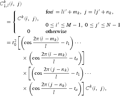
where ![]() is the largest integer smaller than l/2, t p = cos 2π p/l for p = 1, 2, …, t a, and t 0 = 1/(1 − t 1)(1 − t 2)···(1 − t a).
is the largest integer smaller than l/2, t p = cos 2π p/l for p = 1, 2, …, t a, and t 0 = 1/(1 − t 1)(1 − t 2)···(1 − t a).
Considering 1 pixel in the stripe RGB LCD contains 3 subpixels and there is no natural downsampling pattern such as DSD or DDSD for l:1 (l ≠ 3) downsampling, we thus investigate the case of l = 3 for DPD, DSD, and DDSD sampling patterns. For other downsampling ratio l ≠ 3, the analytical model can be extended accordingly. Given l = 3, we have ![]() , and
, and

Taking Fourier transform of (5), we have (6), where ![]() represents the corresponding Fourier transform, ⋆ represents convolution.
represents the corresponding Fourier transform, ⋆ represents convolution. ![]() ,
, ![]() , pk = e j2π/3mk and qk = e j2π/3nk.
, pk = e j2π/3mk and qk = e j2π/3nk.

It is well known that the HVS perceives a color stimulus in terms of luminance and chrominance attributes rather than in terms of RGB values [21]. Hence, we consider to analyze the frequency characteristics of various downsampling methods in the luma-chroma space than directly in the RGB space. To simplify the analysis, we denote the luminance component for the (i, j)th pixel of the pseudo image as 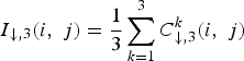 . Taking the Fourier transform of I ↓,3(i, j), and considering (6), we have

where ![]() , and
, and ![]() is the luminance component of original input image, i.e.,
is the luminance component of original input image, i.e., ![]() , and
, and ![]() are linear combinations of RGB color components,
are linear combinations of RGB color components,

Each color component such as ![]() can be decomposed into a low-frequency term
can be decomposed into a low-frequency term ![]() and a high-frequency term
and a high-frequency term ![]() , i.e.
, i.e. ![]() , and since the high-frequency components of different colors tend to be similar [Reference Lian, Chang, Tan and Zagorodnov22], i.e.
, and since the high-frequency components of different colors tend to be similar [Reference Lian, Chang, Tan and Zagorodnov22], i.e. ![]() , we have
, we have

Examining (9), ![]() would be mainly composed by low-frequency signal if
would be mainly composed by low-frequency signal if  . Similar argument is addressed for
 ![]() ,
, ![]() , and
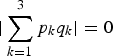
, and ![]() . Take DPD as example, where the sampling locations are identical for R, G, and B color components, i.e., m 1 = m 2 = m 3 (p 1 = p 2 = p 3) and n 1 = n 2 = n 3 (q 1 = q 2 = q 3), none of the
. Take DPD as example, where the sampling locations are identical for R, G, and B color components, i.e., m 1 = m 2 = m 3 (p 1 = p 2 = p 3) and n 1 = n 2 = n 3 (q 1 = q 2 = q 3), none of the  ,
,  ,
,  , or
, or  is zero, indicating that all the neighboring aliasing spectra in
 ![]() contain high-frequency information. Figure 10(a) shows the corresponding typical magnitude of
contain high-frequency information. Figure 10(a) shows the corresponding typical magnitude of ![]() . As expected, there are nine replicated spectra with equal magnitude (
. As expected, there are nine replicated spectra with equal magnitude (![]() ) situated at
) situated at ![]() and
and ![]() in
in ![]() , corresponding to the nine Diracs locations in (7).
, corresponding to the nine Diracs locations in (7).

Fig. 10. (a) ![]() , (b)
, (b) ![]() , and (c)
, and (c) ![]() .
.
Similarly, the sampling locations of DSD are m 1 = m 2 = m 3 and (n 1, n 2, n 3) = (1, 2, 3). We have  ,
,  , and
, and 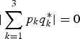 , indicating that the horizontal, diagonal, and anti-diagonal aliasing spectra in
 ![]() may appear much more compact than those of
may appear much more compact than those of ![]() , containing merely low-frequency information, as verified in Fig. 10(b). In terms of DDSD [Reference Fang, Au, Tang, Wen and Wang16], due to diagonal sampling pattern, i.e. (m 1, m 2, m 3) = (1, 2, 3) and (n 1, n 2, n 3) = (1, 2, 3), the arrangement of the nine replicated spectra in
, containing merely low-frequency information, as verified in Fig. 10(b). In terms of DDSD [Reference Fang, Au, Tang, Wen and Wang16], due to diagonal sampling pattern, i.e. (m 1, m 2, m 3) = (1, 2, 3) and (n 1, n 2, n 3) = (1, 2, 3), the arrangement of the nine replicated spectra in ![]() is obviously different from that in
is obviously different from that in ![]() and
and ![]() . The three replicated
. The three replicated ![]() are located in the anti-diagonal direction in DDSD, as shown in Fig. 10(c). Both the horizontal and vertical aliasing spectra merely contain low-frequency information.
are located in the anti-diagonal direction in DDSD, as shown in Fig. 10(c). Both the horizontal and vertical aliasing spectra merely contain low-frequency information.
According to Nyquist criterion, a signal bandlimited to W must be sampled at f s ≥ 2W [Reference Gonzalez and Richard12,Reference Diniz23]. Suppose an image X is obtained by sampling (critically) at such a sampling frequency f s = 2W. If X is to be k:1 down-sampled, the effectively sampling frequency will be reduced to f′s = f s/k. One way to prevent aliasing is to apply a low-pass (anti-aliasing) filter to the signal with a cutoff frequency of f′s/2 = f s/2k. For the image X, recall that the digital frequency of 1 corresponds to analog frequency of f s. Thus the digital cutoff frequency of the low-pass filter is 1/2k. For us, k = 3. Thus, the digital cutoff frequency is 1/6. Nevertheless, with the low-frequency nature of the horizontal aliasing spectra in DSD, the overlap between the center spectrum and the horizontal neighboring spectra is significantly lower than that in DPD. On the other hand, with the smaller amount of horizontal overlap in DSD, it is perhaps possible to use a higher cut-off frequency (larger than 1/6) to retain more high-frequency information in the center ![]() . Compared with DSD, DDSD has the advantage that the center
. Compared with DSD, DDSD has the advantage that the center ![]() overlaps less with the vertical neighbors, even though its overlap with the anti-diagonal neighboring can be considerable. Therefore, while DSD can extend its cut-off frequency beyond the Nyquist frequency horizontally, DDSD can extend its cut-off frequency both horizontally and vertically.
overlaps less with the vertical neighbors, even though its overlap with the anti-diagonal neighboring can be considerable. Therefore, while DSD can extend its cut-off frequency beyond the Nyquist frequency horizontally, DDSD can extend its cut-off frequency both horizontally and vertically.
Figure 11 shows the down-sampled results of conventional pixel-based downsampling with anti-aliasing filter [Reference Gonzalez and Richard12] and the frequency-domain analysis approach previously discussed. As we expected, the frequency-domain analysis approach for DSD and DDSD achieve higher apparent resolution than pixel-based scheme, leading to sharper images. While the frequency analysis approach for DDSD retains considerably if not significantly more details than DSD, due to relatively smaller overlapping of center spectrum and vertical aliasing spectra.

Fig. 11. Down-sampled results using various methods (a) pixel-based downsampling with anti-aliasing filter (PADF), (b) frequency-domain analysis approach for DSD in [Reference Fang, Au, Tang and Katsaggelos24], (c) frequency-domain analysis approach for DDSD in [Reference Fang, Au, Tang and Katsaggelos24].
IV. CONCLUSION
In this paper, we introduce a novel way, i.e., subpixel-based techniques, to increase the apparent resolution when displaying high-resolution image/video on relatively low-resolution portable displays. We start by introducing various subpixel arrangements in different LCDs. Several subpixel-based spatial-domain algorithms are discussed for the purpose of improving the apparent sharpness of font rendering and color image/video downsampling. To study the different frequency characteristics of pixel and subpixel-based schemes, a transform-domain analysis approach is introduced, which theoretically shows that the cut-off frequency of the low-pass filter for subpixel-based decimation can be effectively extended beyond the Nyquist frequency to achieve higher apparent resolution than pixel-based decimation.
ACKNOWLEDGEMENTS
This work was supported in part by the Research Grants Council (RGC) of the Hong Kong Special Administrative Region, China (GRF 610109). Thanks to Editor-in-Chief Dr. Antonio Ortega and three anonymous reviewers for their insightful comments and suggestions.


 Open access