Introduction
In Part 1 of this series of articles proper procedures for reproducibly setting up a transmission electron microscope (TEM) for selected area electron diffraction (SAED) patterns were discussed. It is critical that data from unknown samples are acquired using the same conditions that were used to calibrate the microscope with known samples. In this segment, methods for recording the SAED patterns with digital cameras that provide high-quality centered patterns that are well suited for diffraction software, while protecting the camera from damaging exposures, are presented.
Recording the SAED Pattern Procedure
This is important: only the lowest binning setting of the camera, that is, binning of 1, should be used to record diffraction patterns. This camera setting is the least sensitive to the high intensity of the transmitted beam and intense diffracted beams that often occur during collection of SAED patterns.
1) An initial decision of whether to use a beam block is required. This may depend on the type of pattern being displayed or the type of recording system that is available.
a. No Beam Block: record the pattern using an appropriate exposure.
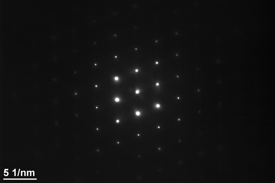
i. Regardless of the type of system available, if a pattern is from a single crystal where the transmitted beam is about the same intensity as the diffracted beam(s), as may occur on a low-index zone axis or a two-beam condition, then a beam block is not necessary (Figure 1). Simply record the pattern with the appropriate exposure.
ii. A beam block might not be necessary if a camera with sufficient dynamic range that will capture the intense transmitted beam and the less intense diffracted spots is available.
iii. A pattern without a beam block present is preferred. For most SAED patterns working without a beam block results in an overexposed transmitted beam region that will oversaturate the camera in the center of the pattern. Typically, if a beam block is not used, gamma processing of the digital image is required to show low-intensity diffraction information in the pattern.
b. Beam Block: record the pattern with “double exposure.”
i. If using film or an imaging plate, a double exposure on a single sheet of film can be acquired by first collecting a long exposure with the beam block stopping the transmitted beam and then a second very short exposure with the beam block removed. This creates a diffraction pattern with a small spot at the center of the pattern.
ii. Use one of the following methods to produce a “double-exposure” pattern using a digital camera.

Figure 1: Si [011] SAED single crystal pattern showing that the beam block is not required when the intensity of the spots is uniformly distributed.
Recording a “Double-Exposure” SAED Pattern with a Digital Camera
A double exposure with film is taken by opening the shutter twice with the same piece of film in place. Of course there is no controlled way of taking a “double exposure” with a digital camera that produces a single image. It is possible to take a “double exposure” with a digital camera by removing the beam block shortly before the end of a long exposure. However, this is not a very consistent and reliable method for collecting the correct exposure for the transmitted beam. However, a long-exposure digital image acquired with a beam block can be added to a short-exposure digital image acquired without one. In Gatan's Digital Micrograph (DM) and with other acquisition programs care must be taken to ensure the image tags (that is, the metadata that carry the calibration parameters) are carried along to the new SAED image. The following procedure describes how to safely take a long- and a short-exposure SAED pattern to create a single image that shows a bright diffraction pattern with a superimposed transmitted beam (000) that marks the center of the pattern.
Method to acquire two SAED patterns:
1) Center the transmitted beam as described in Part 1 of this series. The pattern center should be checked every time. The pattern center will move when changing from imaging to diffraction mode, if it was previously centered, or if the camera length is changed.
2) With the screen lowered, insert the beam block and align it with the transmitted beam. Try to make the intensity that surrounds the beam block as uniform as possible. (Note: If the beam block drifts when inserted, have it tightened by a service engineer so that it doesn't drift. It should take some effort to move it, otherwise it will drift because the vacuum is pulling it in. Exposure times of 60 s or longer are not uncommon for SAED patterns.)
3) Lift the screen and observe the illumination around the beam block. Set the exposure at about 0.1 second and carefully adjust the position of the beam block to obtain uniform illumination around it (Figure 2). Take care not to expose the transmitted beam while doing this. If you accidently move the beam block away from the transmitted beam, be prepared to quickly cover it again, lower the screen, or hit your beam blank button and then lower the screen. (It is important to avoid exposing the camera to a transmitted beam with an exposure that is too high!)
4) Increase the exposure time to obtain a better pattern without saturating the camera. Locate the brightest spot on the image as shown with the yellow circle in Figure 2 and determine the maximum exposure that can be used in the Record image.
a. Calculate the exposure in the Record image by taking into account binning for the View and Record images and the maximum counts to be included in the image. For example, the pattern in Figure 2 acquired with a Gatan Orius camera using a 1.5 s exposure with a binning of 3 gave 8,500 counts for the brightest spot in the (111) ring, indicated by the circle. This camera saturates at 15,000 counts. Calculation of the exposure to use in order to give a maximum count of 14,000 in Record image is given by the equation below:
$$\left(\displaystyle{14,000 \over 8,500} \times 1.5\,s^{`}\right)\times 3^2 = 22.2\,s.$$Figure 2: Enlarged area of the central portion of the SAED pattern from polycrystalline gold showing the uniform intensity around the beam block. The beam block allows a longer exposure to give better SAED patterns. The yellow circle indicates the brightest pixel in the (111) ring of the pattern.
b. This is important! Prior to proceeding, reduce the View exposure to a very short time, similar to the exposure that was used to center the pattern on the crossed lines. Do not leave it at the exposure that was used to determine the Record exposure. In DM, after an image is recorded, the live View image comes back. After recording the image, remove the beam block. It is important that the camera is not exposed to the transmitted beam for a long period of time.
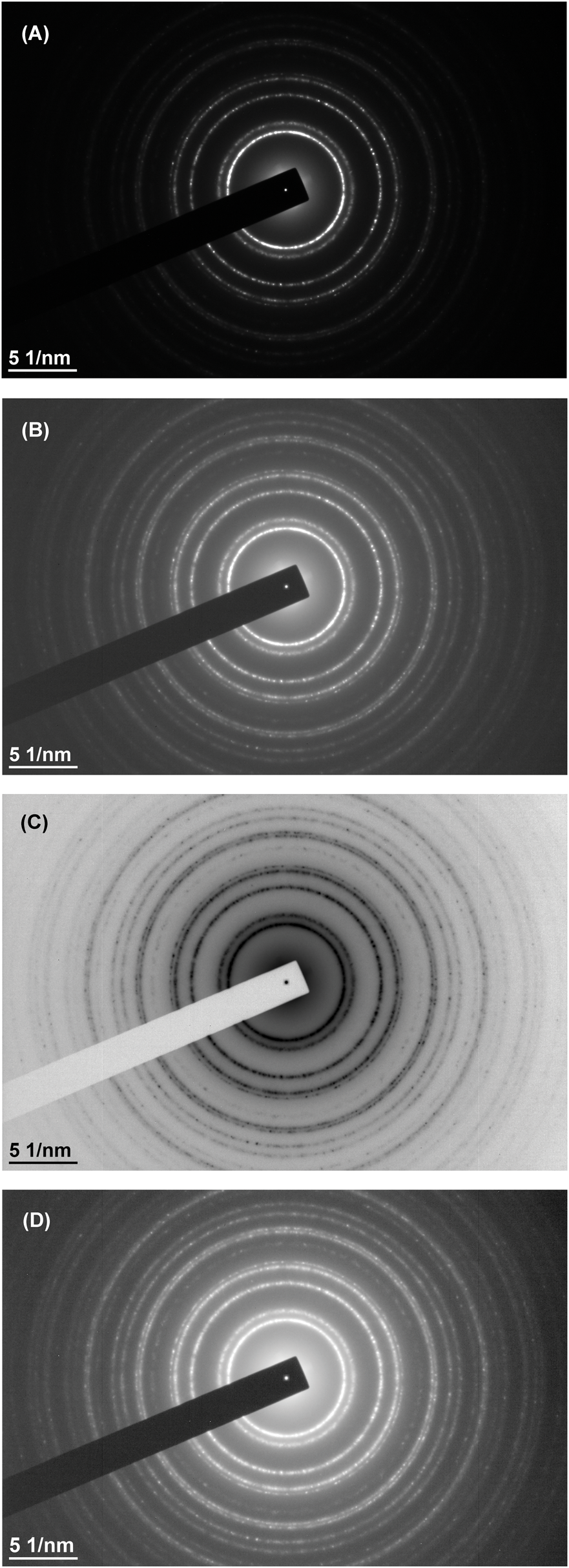
5) Record the SAED pattern with the calculated exposure using Binning 1 (Figure 3A).
a. In DM, while the pattern is being recorded with the long exposure, change the Record exposure to a very short one. This will depend on the number of crystallites in the selected area, the intensity of the transmitted beam due to the diffraction aperture selected, and the amount of open area exposed to the transmitted beam. A very small transmitted beam that is not saturated is optimal. A typical starting value is 0.005 s, which can be adjusted if necessary.
6) Remove the beam block and immediately press Record to take the short-exposure pattern without the beam block present (Figure 3B).
7) As soon as the short-exposure recording is finished, lower the screen or, if available, press Beam Blank on the microscope first, which is faster. This will minimize the time that the camera is exposed to the transmitted beam without the beam block inserted.
8) Save the long-exposure recording and leave both images open in DM. It is not necessary to save the short-exposure recording.
9) Process the image by copying the area of the transmitted beam in the short-exposure recording to the same area in the long-exposure recording and save the image.
10) Follow one of the following procedures to create the “double-exposed” pattern.
Figure 3: Images for creating a “double-exposed” SAED pattern. A) SAED pattern acquired with a 7 s exposure and the beam block inserted. B) SAED pattern acquired with a 0.003 s exposure without the beam block.


Creating the Digital “Double-Exposure” SAED Pattern
There are several ways to add the transmitted spot to the long-exposure image with DM. Regardless of the method used, make sure that the image calibrations are correct in the final image. In DM this means making sure that the image and calibration tags are the same as the original image taken with the beam block inserted.
1) The first method is simply to add the two images together. In DM, this can be achieved with the Menu command: Process-Simple Math – Add – a + b, where “a” and “b” are the two images. The problem with doing it this way is that if the exposure for the diffraction pattern is short, such as would occur with a two-beam condition, then the background of the resultant summation image may be poor. In addition, the tags from the acquired image must be copied to the resultant image. Dave Mitchell's script, “Copy_All_Tags_Between_Images.s,” can be used to do this [1]. An alternative method that preserves the image tags is to write a simple script, such as “SimpleImageSum.s” (Appendix A). Another option, given in the script “ReplaceCenter.s,” is to simply copy a region of interest (ROI) containing the transmitted beam and overlay this in the other image (Appendix B).
2) The second method uses some of the tools in the latest version of DiffTools [2, 3] (V6.1) that must be first installed in DM. This is done manually in a designated sequence but can be automated with the “ChooseMenuItem” script command. Appendix C presents a short script that can be used to automatically generate images (Figures 5A, 5C, and 5D) from the two images shown in Figure 3.
a. Draw an ROI box around the center of the transmitted beam in the image that was taken without a beam block and run the DiffTools menu item, DiffTools – Locate (000) Spot, as shown in Figure 4A.
b. Click on the SAED pattern without the beam block, and then click on the SAED pattern with the (000) spot located. This will put the two images in the correct order for the next DiffTools step. If the sequence of capturing the two patterns is 1) with the beam block in place and then 2) without the beam block in place, the images are already in the required order.
c. Run the DiffTools menu item, DiffTools – Transpose Centre to produce the result shown in Figure 4B. The resultant image retains the calibration tags, and DiffTools also adds the location of the center of the pattern in the image tag that can be used with some of its other tools. The image must be saved to retain the center location tag for future work.
3) The third method uses a slightly more complicated script, but it does not require much user intervention. It also generates two additional images that are image processed. Since the user aligns the transmitted beam with the center of the image with the aid of the crossed lines, the transmitted beam is always contained within a square array of pixels centered about the point where the lines cross. The following is an outline of the algorithm that can be used to write a similar script. The results from applying it to the SAED patterns in Figure 3 are shown in Figure 5.
a. Determine which of the two images has the transmitted beam. One simple and sure way to do this is to subtract the sum of intensities of a center ROI from the sum of intensities of the whole image and compare results for the two images. The pattern with the larger value is the one without the beam block.
b. Create a new image that is a clone of the image with the beam block. This preserves the tag information and gives the basis of the new filename.
c. Replace the data in the square ROI of the image with the beam block with the data from the same ROI in the image without the beam block.
d. Name the new image the same as the image with the beam block and add the suffix “+” to denote that it is the modified file and save it. The resultant image is shown in Figure 5A. Figure 5B shows the image of Figure 5A processed within DM using the gamma control set with a value of 0.62. This image was not processed using a script, but is included here to compare with the other images.
e. Create a “Reveal Weak Reflections” image. This is easily done by using DiffTools and then incorporating the DM script command, ChooseMenuItem(“DiffTools”, “”, “Reveal Weak Reflections”) into your script. This result is shown in Figure 5C.
f. Create a gamma-processed image. You can incorporate Dave Mitchell's “Invert Image Contrast.s” script [4] into this script to invert the Reveal Weak Reflection image and produce a gamma-processed image as shown in Figure 5D.
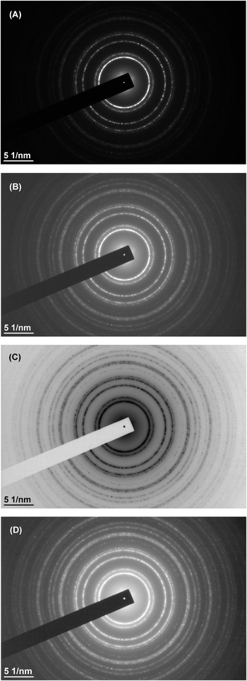
Figure 4: SAED patterns processed with DiffTools. A) Short-exposure image is used to locate the (000) spot. The center of the transmitted beam is found with sub-pixel resolution and reported in a popup dialog box, as shown. B) Long-exposure image with the ROI of (A) transposed to the same area. The center location of the transmitted beam is saved in an image tag. The size of the ROI in this example was intentionally made larger than needed to show the area transposed.
Figure 5: “Double-exposure” SAED patterns. A) Center replaced with transmitted beam from image without the beam block. B) Image (A) manually processed in DM with gamma of 0.62. C) “Reveal Weak Reflections” processed image of (A). D) “Inverted Image Contrast” processed image of (C).

After following the procedures presented in Parts 1 and 2 of this series, a researcher will have a well-calibrated and centered digital SAED pattern with good intensities in multiple reflections and with its center position marked and known. In Part 3 of this series, software used to analyze SAED patterns will be discussed.
Acknowledgements
The research reported in this document was performed in connection with contract/instrument W911QX-16-D-0014 with the U.S. Army Research Laboratory. (As of January 31, 2019, the organization is now part of the U.S. Army Combat Capabilities Development Command [formerly RDECOM] and is now called CCDC Army Research Laboratory.)
The views and conclusions contained in this document are those of the author and should not be interpreted as presenting the official policies or position, either expressed or implied, of the CCDC Army Research Laboratory or the U.S. Government unless so designated by other authorized documents. Citation of manufacturer's or trade names does not constitute an official endorsement or approval of the use thereof. The U.S. Government is authorized to reproduce and distribute reprints for Government purposes notwithstanding any copyright notation hereon.
Appendix A
DM Script: SimpleImageSum.s
// SimpleImageSum.s
// This short script adds the intensities from one image to another image preserving the image tags.
image img0, img1
gettwoimageswithprompt(“0 = Image0 With Beam Block, 1 = Image1 Without Beam Block”,\
“Add Two Images together”, img0, img1)
img0 = img0 + img1
Appendix B
DM Script: ReplaceCenter.s
// ReplaceCenter.s
// This is an alternative short script to replace the center of the image without beam block
// with the center of the image with the beam block.
image img0, img1
number cntrX = 1995 // X position of center crossing lines
number cntrY = 1337 // Y position of center crossing lines
number W = 25 // 2W is size of square box ROI
gettwoimageswithprompt(“0 = Image0 With Beam Block, 1 = Image1 Without Beam Block”,\
“Add Two Images together”, img0, img1)
img0[cntrY-W, cntrX-W, cntrY + W, cntrX + W] = img1[cntrY-W, cntrX-W, cntrY + W, cntrX + W]
Appendix C
DM Script: SimpleAutoDiffToolsTranspose.s
//SimpleAutoDiffToolsTranspose.s
//Arrange SAED Images:
//Front Image - short exp without beam block
//Next image - long exp with beam block.
image img000
number SX, SY, ROIdim
GetFrontImage(img000)
GetSize(img000, SX, SY)
ROIdim = 160 //ROI box is 160 x 160 pixels
SetSelection(img000,(SY-ROIdim)/2, (SX-ROIdim)/2, (SY + ROIdim)/2, (SX + ROIdim)/2)
ChooseMenuItem(“DiffTools”,“”,“Locate (000) Spot”)
ChooseMenuItem(“DiffTools”,“”,“Transpose (000) Centre”)