0] (perpendicular to the coalescence boundary) which originate in the coalescence boundary and extend laterally into the film on the (1
 00). The third set of dislocations threads laterally through the film along the [1
Introduction
High dislocation densities plague GaN films because the commercially available bulk substrates all have substantial lattice mismatch (13.5% for Al2O3, 3.3% for SiC) and thermal expansion coefficient (TEC) mismatch with GaN (34% and 25% for Al2O3 and SiC, respectively). Presumably, eliminating one or both of these sources of mechanical stress is a step towards reducing the defect densities. Lateral epitaxial overgrowth (LEO) relieves components of the lattice mismatch stress by growing part of the GaN film over an amorphous material [Reference Zheleva, Nam, Bremser and Davis1,Reference Kapolnek, Keller, Vetury, Underwood, Kozodoy, DenBaars and Mishra2]. This report describes the dislocation microstructure in a 16µm thick coalesced film grown by the LEO method on a sapphire substrate. TEM images of the entire thickness of the film over five periods of the LEO mask pattern reveal a complex but characteristic arrangement of dislocations, many of which appear not to have their origin in the template.
Experimental Procedures
The LEO substrate was fabricated using conventional CVD processes to grow a 1µm thick GaN template layer (MOCVD with TMGa and ammonia) and a ∼0.1µm thick SiO2 glass mask layer. Openings 2µm wide, oriented along [1
Results
Prior to coalescence, the cross-section of the growing LEO material was rectangular with smooth, vertical sidewalls on (11
High-resolution x-ray reciprocal space maps were recorded using the 0002 point with the stripes oriented both perpendicular (Fig 1a) and parallel (Fig 1b) to the diffractometer plane. The appearance of three distinct peaks in Fig 1a, but not 1b, indicates that the c-axis is tilted + 0.5o about the stripe axis in a portion of the material, presumably over the glass [Reference Fini, Zhao, Moran, Hansen, Marchand, Ibbetson, DenBaars, Mishra and Speck5]. The downward shift of the side peaks corresponds to a relative expansion of the lattice along [0001] in the regions where the c-axis is tilted, a result that is consistent with different levels of in-plane compressive stress existing in the tilted and untilted regions of the material. The significant difference in the diffuse scatter between the perpendicular and parallel maps suggests a highly anisotropic defect structure.

Figure 1. High resolution X-ray diffraction reciprocal space maps recorded with the stripes perpendicular ( Fig 1a ) and parallel ( Fig 1b ) to the diffractometer plane. The three peaks in (a) indicate three distinct orientations for the c-axis, while the difference in the distribution of diffuse scatter between (a) and (b) indicates a highly anisotropic dislocation structure.
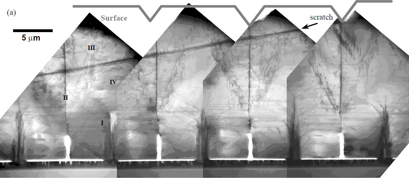
Figure 2a is a montage of TEM images showing four periods of the LEO structure. The schematic in Fig. 2b illustrates the components of the characteristic dislocation arrangement that are repeated in each period. Labeled with Roman numerals in Figs. 2a & b are: (I) a core of threading dislocations (TDs) that are copied from the template, (II) threading and longitudinally oriented dislocations in the coalescence plane (CP), (III) a V-shaped complex of dislocation loops, and (IV) longitudinal dislocations that run along the window axis in the upper part of the film. The arrows in the collection of unit cells in Fig 2c indicate the Burgers vectors (b) for each of these families of dislocations. The threading dislocations in the core have all of the “a” and “a+c” type Burgers vectors that typically populate epitaxial GaN films. The Burgers vectors of the dislocations in each of the other families are a specific subset of these b’s. Limitation to specific b’s indicates that these are introduced into the microstructure to fulfill a particular purpose.

Figure 2. (a) Composite TEM image showing nearly four periods of the LEO structure. Four families of dislocations are labeled: (I) threading dislocations (TDs) copied from the template, (II) dislocations in the coalescence plane, (III) a V-shaped arrangement of rectangular loops, and (IV) longitudinal dislocations lying along the stripe axis.
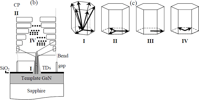
Figure 2 (b) Schematic illustrating the four families of dislocations identified in the film: (I) the core of threading dislocations, (II) coalescence plane dislocations, (III) rectangular loops, and (IV) longitudinal dislocations. (c) Schematic illustrating the orientations of b for each set of dislocations.
(I) Threading Dislocations
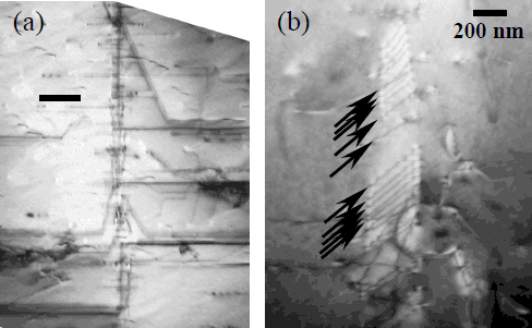
Threading dislocations are copied from the underlying template in the region above the window. In this sample, within 8 µm of growth all the threading dislocations bend away from [0001]. All appear to bend in the plane normal to the stripe axis. Some, but not all, bend 90° to lie on (0001); others prefer one of several other habit planes [Reference Marchand, Wu, Ibbetson, Fini, Kozodoy, Keller, Speck, DenBaars and Mishra6]. As they approach the coalescence plane, at least a subset, if not all, of these dislocations bend again to thread to the surface in the coalescence plane (Fig. 3a). Even if there is no crystallographic tilt, net b, or disregistry at the coalescence plane, there is a dislocation structure in the boundary as a result of the bending threading dislocations. These dislocations do not disappear into the interface, nor do they continue into the next LEO stripe. They could act as sources or sinks for dislocations and point defects and/or provide a mechanism for mechanical deformation at the coalescence plane.

Figure 3. Structure of the coalescence plane. (a) Threading dislocations are displaced from the core to thread to the surface along the CP. (b) Walls of dislocations that lie in the CP with line direction approximately parallel to the substrate have configurations reminiscent of dislocation pile-ups in plastically deformed materials.
(II) Coalescence plane
In addition to the displaced threading dislocations, there is a wall of parallel dislocations (Fig 3b) that lie parallel or slightly inclined to the substrate and have Burgers vectors in the basal plane. These dislocations are present in somewhat dense sets with a local spacing that varies from 40-190 nm along the boundary. Their configurations are reminiscent of dislocation pile-ups in plastically deformed materials. The local dislocation spacings in this segment of the boundary correspond to a lower and upper estimate for the local misorientation across the coalescence plane of 0.16° and 0.43°, assuming b=1/3[11
(III) Rectangular loops
The third set of dislocations consists of rectangular loops in the (1

Figure 4. TEM images showing lateral extent of rectangular dislocation loops. Notice the contrast reversal of the dislocation image when the coalescenceplane is crossed.
(IV) Longitudinal dislocations
The regions above the core of threading dislocations and between the legs of neighboring “V’s” are populated by longitudinal dislocations of the type that have been observed in a number of films [Reference Liliental-Weber, Benamara, Swider, Washburn, Park, Grudowski, Eiting and Dupuis7]. These dislocations have a-type Burgers vectors. The contrast produced where they intersect the surface of the TEM sample suggests that they have a screw component (i.e., Burgers vector other than that of the loops), but additional study of plan view samples is needed to characterize them more completely.
Discussion
Four distinct dislocation families were observed in a thick LEO GaN film grown on sapphire. Each family has specific Burgers vectors, suggesting that they are introduced into the microstructure for a specific reason. The orientation of the Burgers vector in one of the dominant families, the rectangular dislocation loops (III), suggests that they form to in response to stresses other than lattice mismatch. An obvious candidate is TEC mismatch. An analysis of the deformation of the crystal that would be produced by the dislocation loops alone shows their net effect is to cause a contraction of the material in the bar by buckling it like an accordion. Other dislocations would be needed to satisfy compatibility requirements caused by the V-shaped configuration of the loops. Arguments can be made that the longitudinal dislocations in the coalescence plane and the LEO material satisfy these requirements, but further Burgers vector analysis and examination of the driving force would be needed to establish this mechanism unambiguously.
Conclusions
The dislocations observed in a thick, coalesced LEO GaN film on sapphire form a complex but characteristic arrangement, and do not appear to be solely copied from the template. While wing tilt and TD bending are commonly observed in LEO films, the observation of additional sets of dislocations with specific Burgers vectors suggests a large scale cooperative motion in response to the in-plane compressive stress or other driving forces.
Acknowledgements
This work was funded by the ONR-MURI on Compliant Substrates. Partial support for the electron microscopy facilities was provided by the NSF-MRSEC at UW-Madison.