


1. INTRODUCTION
The seascape is changing in terms of beacons used as short range Aids to Navigation (AtoN) to provide regulatory guidance and information to vessels. Their traditional role to help navigators determine their position, follow a safe course and avoid dangers and obstructions remains unchanged. However, the methods used for implementation and presentation to navigators and watchstanders on the bridges of vessels are evolving and expanding using new technologies. The results are a wider range of more capable AtoN that can now be deployed in more locations to supplement existing AtoN, as well as to regions where environmental factors and remoteness have in the past prevented AtoN use. Instrumental to this change is the concept of virtual electronic AtoN (eAtoN) presently implemented using Automatic Identification System (AIS) radio technology viewable on the bridge where eAtoN can be projected to locations where no physical AtoN exists. These may also be included within Electronic Navigation Charts (ENC) and displayed using Electronic Chart Display and Information Systems (ECDIS).
The nature and outcome of new research is described focusing on the creation of truly virtual eAtoN that require no physical infrastructure whatsoever and are intended for use where physical AtoN and AIS eAtoN are impractical. This includes the Arctic where ice can hole and sweep away buoys from their intended locations, the tropics where sinkers cannot be placed on ecologically sensitive coral reefs, and other areas where navigational infrastructure does not exist or has been destroyed due to war or natural disaster. This concept is more than simply placing a symbol on a chart as it includes high-resolution hydrographic and geospatial data correlation of the physical environment to virtual eAtoN characteristics essential to their operation. This physical data is also used to verify eAtoN are watching properly, defined by the US Coast Guard as, “an aid to navigation on its assigned position exhibiting the advertised characteristics in all respects” (USCG, 2005a). The described implementation can overcome many vulnerabilities of Global Navigation Satellite Systems (GNSS) and AIS, technologies essential to modern vessel navigation.
2. JUSTIFICATION FOR VIRTUAL eAtoN
A marine AtoN is a device or system external to vessels that is designed and operated to enhance the safe and efficient navigation of vessels and/or vessel traffic (IALA, 2014a). There are limitations to the present AtoN system that impede expansion to geographic regions which are experiencing significant growth in marine traffic yet are highly remote and ecologically fragile. In the United States this includes thousands of square miles in the Arctic encompassing the northern slope of Alaska, the Aleutian Islands, tropical regions spanning the Hawaiian Islands to Midway Atoll and other US territories. Figure 1(a) illustrates the volume and transit patterns of vessel traffic along a portion of Alaska's northern slope based upon ships using AIS to transmit their position and other information (NOAA, 2015). These same areas are poorly charted, if they are charted at all. According to the US National Oceanographic and Atmospheric Administration (NOAA), the Arctic is severely deficient in many capabilities extended to the rest of the nation and large gaps exist in the information it does have illustrated by empty white space on nautical charts of the region (NOAA, 2011; 2013). This is shown in Figure 1(b) where empty white space is interrupted occasionally by track lines and spot soundings that are often many miles apart.
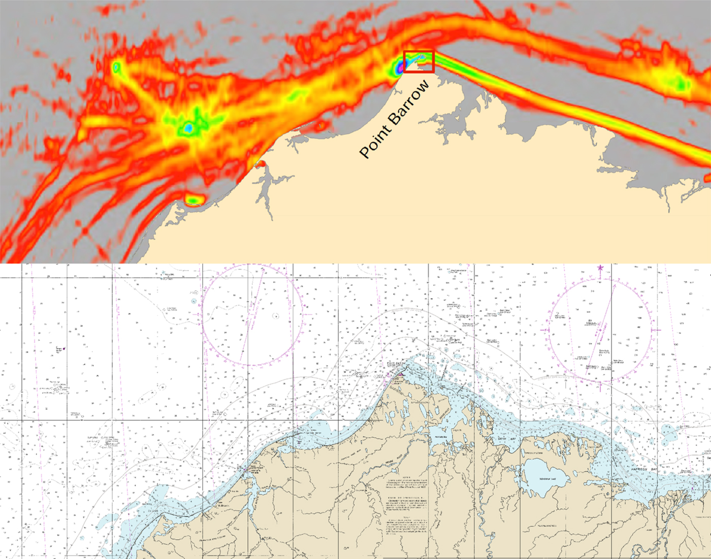
Figure 1. Comparison of AIS tracking of vessel volume and transit routes to official nautical charts of the northern slope of Alaska, US.
(a) (top) AIS vessel tracking across the Chuckchi and Beaufort Seas. (source: NOAA, 2015). (b) (bottom) Mosaic of NOAA nautical charts 16004 and 16005 illustrating large areas of unsurveyed bottom.
The scale of these charts is 1:700,000, therefore the soundings appear inordinately large compared to the actual geographic areas represented. According to the U.S. Coast Guard, a situation to be avoided unless specifically warranted by unusual circumstances is the establishment of AtoN in areas not properly charted or where they would invite the inexperienced to attempt a passage which would still be dangerous in spite of the AtoN (USCG, 2005b). The phrase “unusual circumstances” can be applied directly to the Arctic, where vessel traffic is increasing and traditional AtoN systems are inadequate and not practical. Virtual eAtoN can overcome many limitations that afflict physical AtoN and AIS eAtoN in these remote and harsh locations. A significant need can be fulfilled using eAtoN for vessels to transit safely and efficiently and avoid unintentional groundings, obstructions and hazards to navigation. The problem of hydrographic survey insufficiency in much of the region can be solved using 3-Dimensional Forward Looking Sonar (3D-FLS) to assist vessels of opportunity to safely navigate uncharted waters while simultaneously capturing high-resolution, full bottom coverage swaths of sonar data that can assist in the development of nautical charts.
3. AIDS TO NAVIGATION: AN OVERVIEW
AtoN systems are intended to facilitate safe and efficient movement of vessels through a waterway. Their responsible provisioning requires that systems be designed to meet the minimum requirements for safe and expeditious navigation through special waters in accordance with the type and volume of traffic and the degree of risk. Requirements will change due to revised circumstances, the introduction of new technologies and increased demands by crews, vessels and operations. The means to fulfill new requirements must also change through the use of modern techniques, new tools and implementation methodologies in the analysis of sites, needs, simulation, and operations. In assessing modern AtoN system requirements, three primary elements illustrated in Figure 2 must be considered in terms of system functions, capabilities and the duration of the services provided by AtoN.
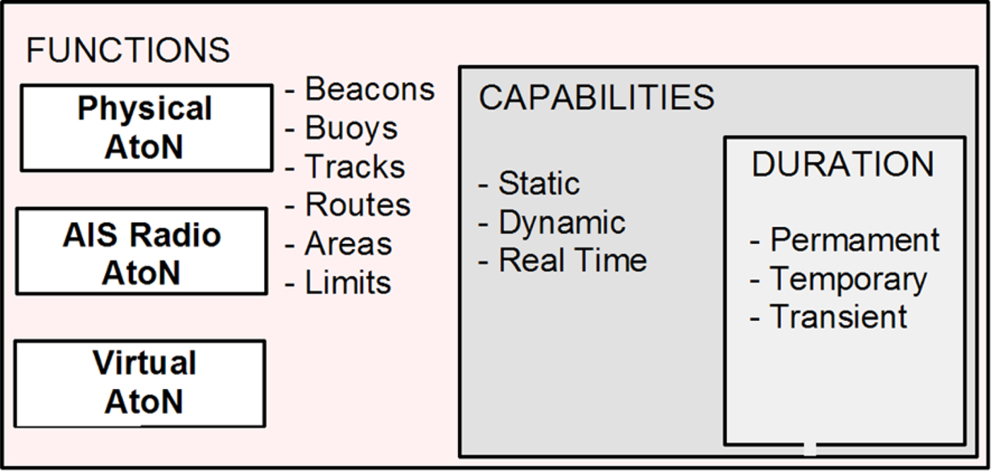
Figure 2. Aids to Navigation (AtoN) elements pertinent to safety of navigation.
3.1. Functions
The traditional functions accorded to mariners by AtoN have been manifest as physical beacons and buoys whose functions based upon colour, shape, topmarks and other characteristics have explicit meaning in the context of their use. Their placement within an overall AtoN system is used to denote tracks, routes, areas and limits implemented across the entire waterway using a systematic approach. Emulation of these same functions can be accomplished using AIS radio-based eAtoN and virtual eAtoN to supplement physical AtoN. They may also be used in their stead when the deployment of physical AtoN or AIS eAtoN is difficult or impossible. However, both AIS and virtual eAtoN can provide additional capability to facilitate the electronic display of lines and symbols that represent areas, routes, tracks and limits directly on ECDIS without having to emulate the physical AtoN that are typically used to denote these functions.
3.2. Capabilities
Historically the capabilities for implementing AtoN functions have been viewed from a static point of view where, upon completion of a waterway design, physical AtoN are deployed to required locations. The ability to provide dynamic AtoN capabilities where their characteristics can change based upon a function of time and other factors has only recently been accomplished using AIS radio-based eAtoN broadcasting area special messages. One example is their use to broadcast race boundary lines that appear on spectators’ electronic charts marking a safety zone during the 2013 America's Cup races in San Francisco (Queeney, Reference Queeney2013). Exploration of AIS dynamic operational information from both ship and shore installations can lead to further enhancement of AIS eAtoN capabilities. Real time reporting capabilities are inherent in the design of physical AtoN by virtue of their presence in the environment at the time they are viewed. Similar capabilities can exist using AIS eAtoN to report the position of sensor arrays and other tows. Virtual eAtoN can also be used to display in real time underwater hazards to navigation detected using 3D-FLS.
3.3. Duration
The use of physical beacons and marks continues to be the preferred method of physical AtoN deployment for channels, routes and other locations. Changes are made primarily resulting from experience and maintenance issues as they arise and not based upon new design and implementation methods. AIS eAtoN can also be used to permanently mark features that are difficult to mark using physical AtoN such as the Isolated Danger mark located on Tarapunga Rock in Doubtful Sound near the South Island of New Zealand (Marinetraffic VIRT, 2016). Virtual eAtoN can also perform the temporary marking of wrecks and other features in addition to marking transient features that have very short or momentary significance such as a shipping container that is adrift, growler or whale directly in the path of the vessel.
4. eAtoN IMPLEMENTATIONS
A beacon is defined by the International Association of Marine Aids to Navigation and Lighthouse Authorities (IALA) as “a fixed artificial navigation mark” that can be recognised by its shape, colour, pattern, topmark or light character, or a combination of these (IALA, 2014b). Beacons are realised in the IALA Maritime Buoyage System (MBS) using piles or buoys as Lateral Marks, Cardinal Marks, Isolated Danger Marks, Safe Water Marks, Emergency Wreck Marking Buoys and Other Marks (IALA, 2014c). They are used to mark a landfall position, obstruction, danger or area; indicate lateral limits of a channel and navigable waterway and turning points or junctions, bearings or lines of position. The methods described using the IALA Region B MBS applicable to the Americas, Japan, Korea and the Philippines also apply to the IALA Region A MBS (IALA, 2014d).
4.1. AIS eAtoN
The eAtoN concept has recently been introduced using AIS radio technology to emulate the characteristics of physical AtoN using their electronic equivalents. Their capabilities for rapid deployment and update have proved very useful in operational situations. AIS eAtoN may or may not be present at the deployed location, depending upon their method of implementation which includes the following (IALA, 2008):
-
• Real: AIS signal broadcasts originate from a physical AtoN,
-
• Synthetic: AIS signals originate from a remote AIS base station and are broadcast to a location where a physical AtoN exists, and
-
• Virtual: AIS signals originate from a remote AIS base station and are broadcast to a location where no physical AtoN exists.
Infrastructure to support Very High Frequency (VHF) transmitters, receivers, power and health monitoring must be present at a suitable location in the local environment within line-of-sight to the AIS eAtoN deployment location due to radio range limitations. This requirement for physical infrastructure limits their deployment to accessible regions where personnel and vessels to support the installation and maintenance of these aids are available. Hundreds of locations exist worldwide where AIS eAtoN are currently deployed, with the vast majority being Real and Synthetic aids. Their capability to emulate physical AtoN can support new functionality that is not possible with physical AtoN. Using the symbols shown in Figure 3 charts currently produced by NOAA with AIS eAtoN present within ENC are displayed on ECDIS (NOAA, 2013b). A second line in this table has been added to suggest possible symbols for (non-AIS) virtual AtoN display on ECDIS omitting the magenta radio station circle and text for AIS. Not all systems are presently equipped to display many of the symbols currently identified for ECDIS use. Introduction of an extended symbol set into new ECDIS systems will begin in 2017 and continue after this date for older systems. Symbols similar to those shown in Figure 3 are also contained in raster and printed charts to depict virtual AtoN.
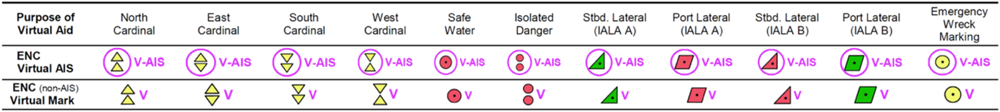
Figure 3. Present AIS virtual eAtoN symbols with suggested non-AIS virtual eAtoN symbols.
AIS eAtoN have been tested to mark the entrance to a Traffic Separation Scheme (TSS), provide emergency wreck and obstruction markings, identify waypoints and turning points, supplement existing physical AtoN, mark bridge abutments and offshore structures alone and in groups to make them more visible. Examples of wreck marking include a sunken former Russian Whiskey class submarine off Denmark in February 2007 and the cargo vessel Omar N that capsized in the Baltic Sea in October 2007 (FRV, 2009).
In 2008 AIS eAtoN were used to aid vessels on the approaches to the southern end of Drogden Channel between Denmark and Sweden. In 2014 the US Coast Guard began testing synthetic and virtual AIS eAtoN to mark reporting points in the offshore TSS approaches to San Francisco as shown in Figure 4. They are also used to mark the bridge towers to better alert mariners of their presence on the western span of the San Francisco-Oakland Bay Bridge as shown in Figure 5 (USCG, 2014). Many additional AIS eAtoN have been deployed along both coasts, in the Great Lakes and in the interior along portions of the western rivers within the US (Lewald, Reference Lewald2015).
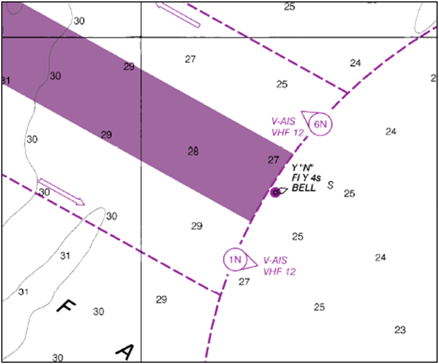
Figure 4. AIS AtoN Marking the Entrance and Exit from the San Francisco Traffic Separation Scheme. Source: NOAA Chart 18645
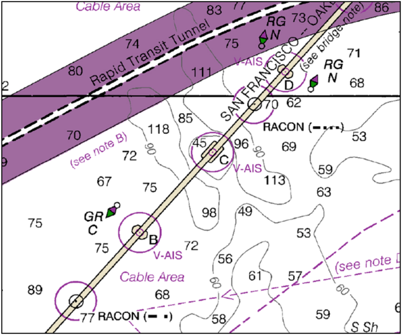
Figure 5. AIS AtoN Marking Bridge Towers on the San Francisco-Oakland Bridge. Source: NOAA Chart 18645
4.2. Virtual eAtoN
The virtual eAtoN concept is enhanced beyond AIS eAtoN technology as computer-generated and existing entirely as a digital data object with no corresponding presence in the physical environment required for implementation. Virtual eAtoN also include expanded functional elements beyond AIS eAtoN to support static, dynamic and real time elements with permanent, temporary and transient durations. The basic definition of a virtual aid to navigation is (IALA, 2010):
“A virtual aid to navigation (Virtual AtoN) does not physically exist but is a digital information object promulgated by an authorised service provider that can be presented on navigational systems”,
where a digital information object is further defined as:
“An item or group of items, regardless of type or format that a computer can address or manipulate as a single object that will inform the user as to the characteristic of a Virtual AtoN”.
This definition is further amplified to describe Virtual AtoN use in informing mariners about dangers to navigation, safe waterways, caution and avoidance areas as may be represented by a line, area, position or other form displayed graphically without providing specific implementation mechanisms. Recommendations provided for the provisioning of Virtual AtoN and their deployment under the International Maritime Organization (IMO) e-Navigation initiative have thus far been limited to AIS eAtoN that use VHF radio technology (IALA, 2011; NCSR, 2014).
The characteristics and benefits of virtual eAtoN have been explored by Wright and Baldauf (Reference Wright and Baldauf2014) in research designed to enhance the safety of navigation for vessels in regions that are uncharted or poorly charted. Each of these types of AtoN has their unique functions, characteristics and associated advantages and disadvantages that determine how and where they may be deployed and how they are used by mariners.
4.2.1. Functions
Virtual eAtoN can provide the same beacon functions as AIS eAtoN along with additional functionalities pertaining to areas and limits, and tracks and routes that are not possible with either physical AtoN or AIS eAtoN.
4.2.1.1. Beacons and Buoys
Figure 6 illustrates the placement of virtual eAtoN lateral marks at the entrance to and along a channel that is particularly difficult to mark with physical AtoN in Kotzebue, Alaska, US.

Figure 6. Portion of NOAA Chart 16161 for Kotzebue Harbour, Alaska, US depicting the placement of non-AIS virtual eAtoN where physical AtoN are normally not shown.
Located 26 miles inside the Arctic Circle, much of the area is not surveyed and there are constantly changing sandbars along the approaches. A note to this effect is posted on the nautical chart along with advice to seek local knowledge when using this route that spans several miles from clear water to Kotzebue Harbor. Physical AtoN are placed each season along this route but are not marked on charts due to their varying positions. This location provides circumstances advantageous to determining the viability of virtual eAtoN as it represents a transitional point where VHF radio coverage is also suitable for AIS eAtoN operation. This makes it useful to evaluate the integration and performance of AIS eAtoN and virtual eAtoN. The route is also sufficiently travelled to offer useful experience and feedback in their operation from numerous vessels.
A prime location for the use of virtual eAtoN is remote and not easily accessible for AtoN installation and maintenance and exhibits one or more hazards to navigation that, if left unmarked, may result in significant risk to life, property and the environment. One such example is shown in Figure 7 along a possible Bering Strait TSS providing northbound and southbound traffic lanes through the narrow passage around Big Diomede Island in Russia and Little Diomede Island in Alaska, US (MarEx, 2015). A hazard to navigation exists as Fairway Rock to the south and east of Little Diomede Island.
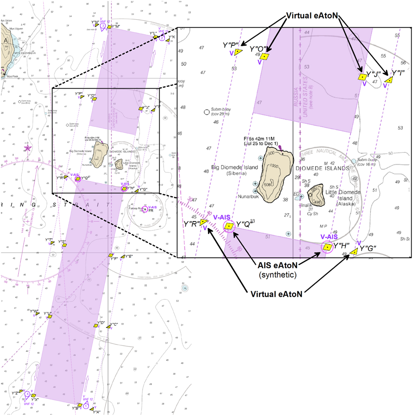
Figure 7. Portion of NOAA Chart 16220 showing a possible Bering Strait TSS and placement of both AIS and virtual eAtoN.
Virtual eAtoN placed at entrance and exit positions along the TSS and along the transit path centreline or at lateral positions would define the route. These could be mixed with AIS eAtoN along the lanes of the TSS using VHF transmitters located on Big Diomede and Little Diomede Islands respectively, with one additional AIS eAtoN transmitting from Fairway Rock also possible. This figure depicts the use of virtual eAtoN in combination with AIS eAtoN special purpose TSS buoys marking the port and starboard sides of the traffic lanes separated by the two islands along with radio reporting points at the ends of each lane.
Marking of hazards to navigation that heretofore has been difficult or impossible due to the harsh environment and lack of accessibility may now be accomplished. This includes sites such as the previously discovered but uncharted ledge in Resolute Bay, Canada upon which MV Clipper Adventurer grounded in 2006 (TSB, 2012). In this respect it might be reasonable to further integrate and investigate the potential of virtual eAtoN for enhanced route, position or direct grounding warnings or alarms.
4.2.1.2. Tracks and Routes
In addition to virtual eAtoN temporarily marking beacons, areas and limits, their use can be advantageous to mark tracks and routes in cases where knowledge of previous recent transits can directly contribute to increasing the safety of navigation. One such example is the track of an icebreaker where the route of transit may provide guidance to where ice may be substantially thinner and more suitable for navigation. In this case it is likely the best representation would take the form of a non-regulated recommended track not based on fixed or virtual marks. Virtual eAtoN encoded characteristics represented by this track should include vessel name and time of most recent transit, an expiration date and time when the virtual eAtoN is no longer valid, heading information and possibly the shoalest depth value along a track as illustrated in Figure 8. Should previous hydrographic survey data exist along the route of transit this information would already be included in the ENC. However, when depths in the track are not known due to lack of survey a reported shoalest depth using single-beam echo sounder measurements from the icebreaker may be encoded but identified as being unreliable.
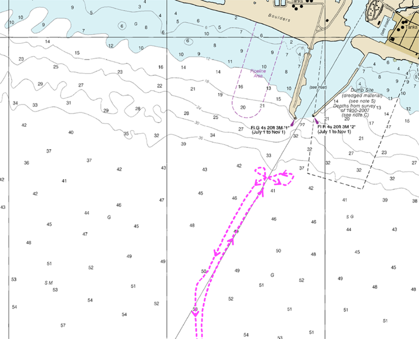
Figure 8. Portion of NOAA chart 16206 depicting virtual eAtoN icebreaker track on approaches to Nome, Alaska.
4.2.1.3. Areas and Limits
Virtual eAtoN may also be used to mark specific geographic areas such as the Bering Sea and Aleutian Islands groundfish fishery designated conservation areas and protection zones. The availability of such functionality is valuable where conservation measures requires rapid action to temporarily and spatially limit fishing efforts, especially in relation to closures around areas involving marine mammals. One such implementation is shown in Figure 9(a), where transit of the area is normally allowed between 1 April and 15 August with a permit. During times when walrus activity is high it may be necessary to restrict entry with little advance notice during the normally open to transit period as shown in Figure 9(b) (FMP, 2015). This may be accomplished using virtual eAtoN depicting area and limit boundaries without having to emulate one or more buoys to achieve this same purpose. These boundaries may also rapidly expand and contract as local needs dictate. Such functions can be used to place no-entry zones and advisory areas near to coral reefs and other ecologically sensitive areas, disaster areas, race and other events that require time and spatial restrictions. This applies to other restrictions that pertain to offshore wind farms, fishing, anchoring and diving as well as marking bird and seal sanctuaries and marine parks.
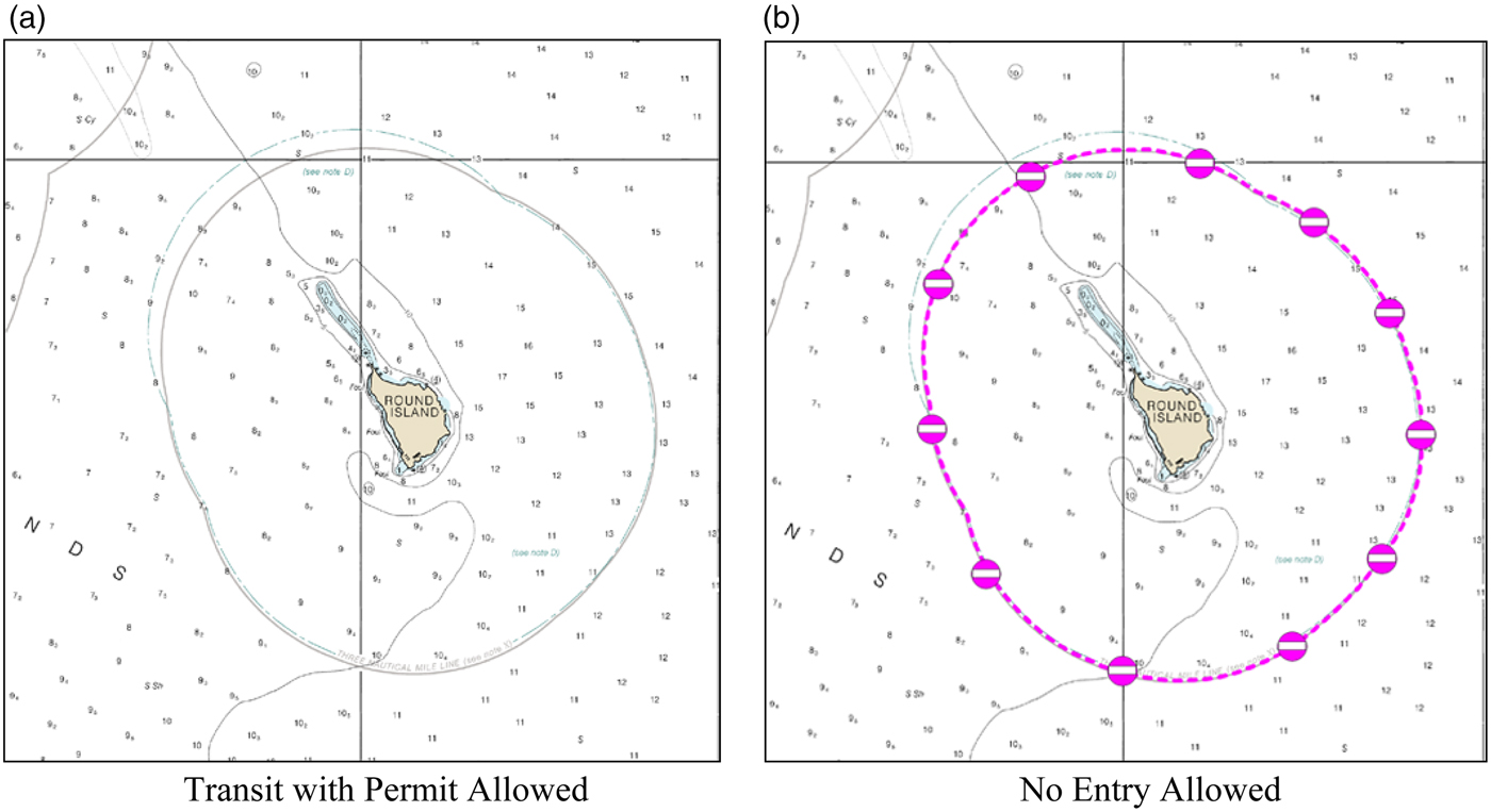
Figure 9. Portion of NOAA Chart 16315, Bristol Bay, Alaska depicting the Round Island virtual eAtoN walrus protection area: transit permit active and inactive.
Virtual eAtoN use in poorly surveyed regions where physical and AIS eAtoN are not practical can also enhance the safety of navigation where charting data is inadequate or does not exist at all resulting in blank white spaces on nautical charts. The use of aids to navigation in such areas is greatly restricted since the knowledge of where to place them is deficient due to lack of soundings. To help solve this problem research was performed using 3D-FLS for navigating poorly surveyed regions to avoid unintentional groundings (Wright and Baldauf, Reference Wright and Baldauf2015a). Further research involved assessing the usefulness, resolution and accuracy of 3D-FLS to supplement hydrographic survey resources as externally sourced data (Wright and Zimmerman, Reference Wright and Zimmerman2015). The findings indicate that it is possible to perform examination with full bottom coverage using 3D-FLS to obtain an accurate characterisation of the sea floor, useful for nautical chart development and virtual eAtoN placement. Figure 10 provides an example of how multiple special purpose virtual eAtoN beacons may be placed along a track with a swath of sonar data where neither soundings nor AtoN previously existed, itself a virtual eAtoN representing an area. This data can be obtained from a vessel of opportunity equipped with 3D-FLS and used to define a route in an uncharted area.
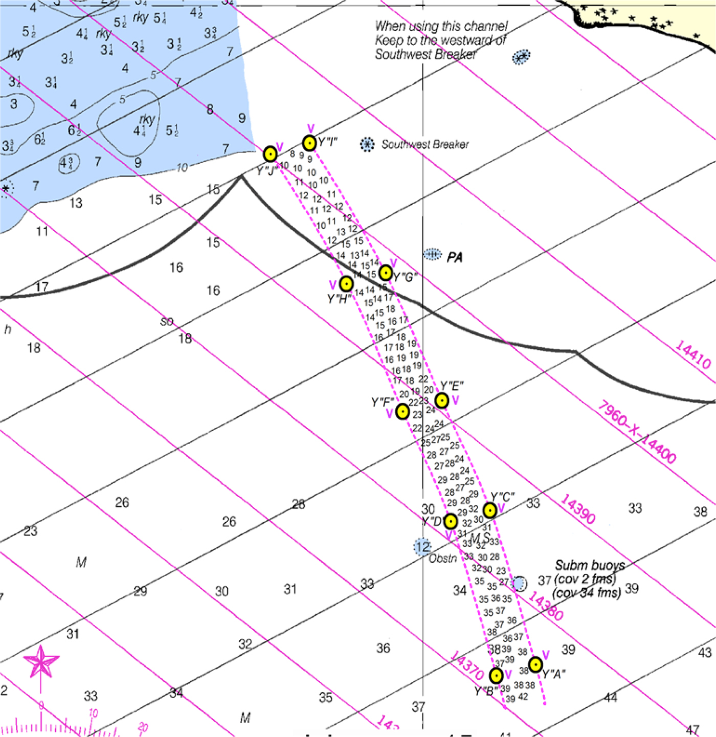
Figure 10. Portion of NOAA chart 16723, Controller Bay, Alaska, US depicting virtual eAtoN special purpose buoys and soundings swath from 3D forward-looking sonar equipped vessel.
4.2.2. Capabilities
Beyond the functions virtual eAtoN are able to provide in terms of use are the capabilities through which these functions may be delivered and observed on the bridge of the vessel while underway. This can also extend to shore-based vessel traffic service operators (including fleet operation centre operators), vessel owners and others involved in supervising vessel activity. Many of these capabilities are new, having become possible due to detailed hydrography data integrated within the International Hydrographic Organization (IHO) S-100 framework standard Universal Hydrographic Data Model and specifically the draft S-102 High Definition Gridded Bathymetry standard that supports development of new navigation products not possible under the S-57 and previous standards (S-102, 2012).
4.2.2.1. Dynamic Virtual eAtoN Positioning for Marking Coaxial Waterways
One example of new capability is dynamically repositioning virtual eAtoN considering vessel physical and performance characteristics rather than to maintain fixed geographic positions regardless of vessel size and draft requirements. This can be used to mark a deep draft channel within a wider waterway, a portion of which is illustrated in Figures 11(a) and 11(b), and is different from related ECDIS capabilities as the physical bottom configuration characteristics of the virtual eAtoN existing within ENC are used together with vessel draft parameters and live single-beam echo sounder measurements to determine lateral spacing requirements for channel width. This is based upon detailed hydrographic surface topography model data and is accomplished in real time considering bottom depths and the forward motion of the vessel. Here it is shown that the bottom configuration offers a much broader geographic area for the safe navigation of a vessel with a two metre draft compared to a vessel with a four metre draft where the vessels travel at the same speed.
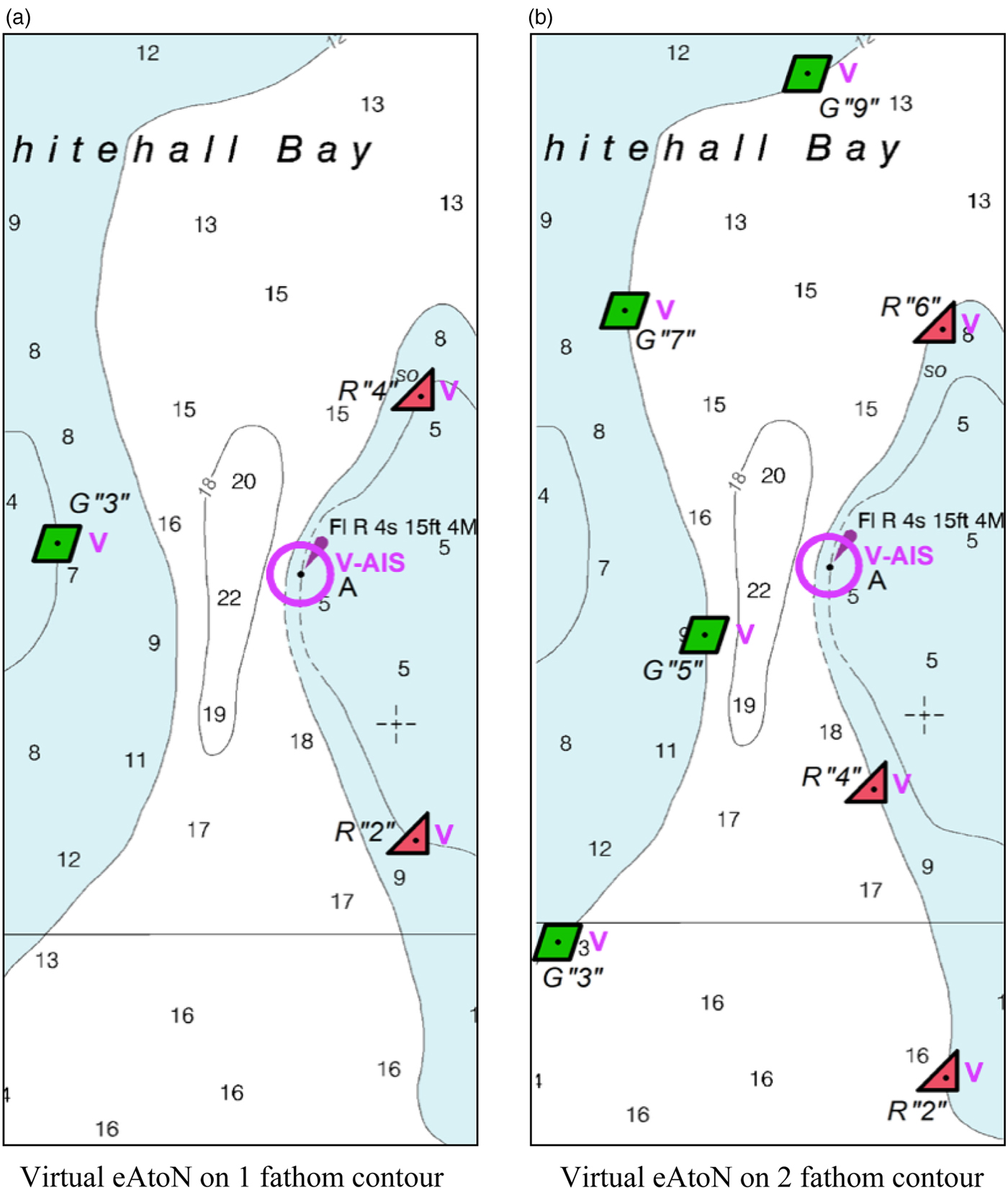
Figure 11. Portion of NOAA chart 12283, Annapolis, Maryland, US depicting mix of fixed position AIS eAtoN and dynamic positioning of virtual eAtoN to mark coaxial waterways.
4.2.2.2. Single and Group Virtual eAtoN
An additional layer of abstraction in the overall AtoN scheme has been added with AIS virtual eAtoN that may be placed on physical AtoN to supplement their characteristics, and at locations other than AtoN to project AtoN characteristics to locations where no AtoN exist at all. The introduction of completely virtual eAtoN provides an opportunity to further extend AtoN capabilities to create a “group” virtual eAtoN representing a “system of systems” that together provides capabilities beyond the sum of the individual virtual eAtoN components is comprised. For example, the Kotzebue channel shown in Figure 6 and the possible configuration of a Bering Strait TSS shown in Figure 7 can support new capabilities by linking individual virtual eAtoN characteristics when accompanied by detailed hydrographic surface model data in an ENC. This can include automatic determination of changes and shifting of bottom contours resulting from storm action and other causes by comparing the ENC terrain model data with live echo sounder measurements while underway. This same process could be used to detect whether AtoN (physical, AIS or virtual) are on station and watching properly in good water. Furthermore, this technique would rapidly detect poor GNSS availability due to atmospheric interference, spoofing or a denial of service attack taking place that results in the apparent vessel position being different from the actual vessel position based upon differences in bottom topography.
4.2.2.3. Real-time Hazard to Navigation Detection
Virtual eAtoN can be used to contribute new alarms and methods to notify in real time watchstanders on the bridge of the detection of uncharted hazards to navigation when integrated with 3D-FLS adequate to support this capability. This includes shoals, ledges and rocks, as well as floating hazards and those suspended in the water column in the path of transit based upon research performed by Wright and Baldauf (Reference Wright, Baldauf and Weintrit2015b). Notable case studies were presented illustrating how MVs Clipper Adventurer, Exxon Valdez, Rena and Costa Concordia could have been provided 1·7 to 2 minutes advance warning of grounding had 3D-FLS been installed and operational. This would have also been useful for a situation such as was encountered by Carnival's Ecstasy in April 2010 which responded in very short time to miss a large, partially submerged data buoy adrift in the Gulf of Mexico (Yanchudas, Reference Yanchudas2010).
The detection of such hazards to navigation can be accomplished using algorithms already available within 3D-FLS. However, their display to watchstanders must conform to existing human-machine interface conventions and standards. Hazards to navigation may be displayed on ECDIS by placing an isolated danger mark shown in Figure 3 directly at one or more positions where contact was made using 3D-FLS as illustrated in Figure 12. The background shown within this figure corresponds to many poorly charted and uncharted locations in the Arctic where ECDIS is essentially blank since the underlying ENC contains no or sparse sounding information. The isolated danger marks shown in this figure represent a hazard to navigation detected in real time while making way and within the range of the 3D-FLS providing a significant acoustic target when compared to surrounding waters. These targets can represent a shipping container, growler, whale or other target. A transient virtual eAtoN is something that is neither permanent nor temporary in nature, and is likely to exist only momentarily until the hazard passes. Such an approach is wholly unorthodox in terms of the present AtoN development lifecycle as the mark has not been promulgated by a competent authority. However, consideration by a competent national authority of the processes that make such capabilities possible through the integration of new technologies must be considered, especially when risk is heightened while transiting unknown waters.
Figure 12. Live display of real time virtual eAtoN isolated danger mark using 3D-FLS integrated with ECDIS.
4.2.3. Virtual eAtoN Adoption
Examples of virtual eAtoN realised as beacons, areas and limits, and tracks and zones are provided to illustrate functions that are possible. The capabilities described to employ these functions are also illustrative, as are the specific characteristics that have been described for implementation. Determination of virtual eAtoN adoption for future test, evaluation and/or operational use must be made by the competent national authority after the development and validation of the processes required to assure their performance and technical viability have themselves been validated.
4.2.4. IHO S-100 Framework Standard
A key component of virtual eAtoN implementation includes high resolution three-dimensional digital terrain model data of the sea bottom incorporated into ENC represented as IHO S-102 High-Definition Gridded Bathymetry featuring level 1 (harbour) 0·02° x 0·02° grid sizes and a final surface grid resolution of 0·0001° or approximately 8 metres (Journault et al., Reference Journault, Maltais and Kuwalek2012). Sufficient resolution exists within these data to perform the verification of virtual eAtoN physical characteristics using the metrics described and illustrated by Wright and Baldauf (Reference Wright and Baldauf2015c). Similar resolution available from 3D-FLS data as a source for hydrographic survey data from vessels of opportunity in inadequately surveyed areas can accelerate the deployment of virtual eAtoN (Wright and Zimmerman, Reference Wright and Zimmerman2015). Issues yet to be resolved include the transport architecture that will be used to convey ENC from shore to on board vessels, cyber security enhancements needed to ensure trust in data sources, training in the use of this infrastructure and the range of new products to be delivered. One issue still to be addressed is the orientation of gridded data with the meridians and parallels at the higher latitudes of the Arctic.
5. CONCLUSIONS
The ability of virtual eAtoN to emulate beacons and buoys, tracks and routes, areas and limits and other functions with minimal investment and recurring cost for physical assets and support infrastructure is very appealing to supplement physical AtoN and AIS eAtoN in the many inaccessible, remote and ecologically sensitive regions of the world. The trend of increasing budget constraints for AtoN research, development, deployment and maintenance is contrasted with the rise in vessel traffic in regions that are the least amenable to support such traffic. These regions are the least surveyed, most remote, devoid of AtoN infrastructure, lacking safe harbours and adequate search and rescue capabilities, and among the most ecologically fragile on the planet.
Results of this research reported to date indicate a realistic potential for the use of virtual eAtoN, especially in locations and regions where traditional AtoN are not practical or feasible. Evidence has been presented to indicate the proposed approach provides advantages over physical AtoN and AIS eAtoN in overcoming the vulnerabilities and limitations of GNSS and AIS technology. New functions and capabilities available using virtual eAtoN integrated with 3D-FLS can provide significant enhancements to safety of navigation especially in regions that are not surveyed and remain uncharted such as the Arctic. An initial starting point may include the adaptation of existing 3D-FLS in-water hazard and obstruction detection algorithms to produce standard ECDIS symbology. Also, the Polar Code should be amended to mandate 3D-FLS as an echo-sounding device having forward-looking capabilities as a vessel carriage requirement in the Arctic (MSC.385(94), 2014). Alternatively, 3D-FLS should qualify as one of the two already required independent echo-sounding devices.
The concepts involved have already been proven in the aviation industry, where aircraft plying the airways at speeds orders of magnitude faster than vessels at sea routinely navigate in safety. All airborne AtoN are virtual. There is not one physical AtoN suspended in the air to help guide aircraft to their destinations. The described implementation of maritime virtual eAtoN is firmly grounded in high-resolution geodetic data traceable directly to the local environment in which they are deployed. Such characteristics provide the means by which assurance of their correct implementation and watching properly can be established and continuously monitored. These concepts can be extended to existing physical AtoN and AIS eAtoN, enhancing overall confidence in short-range AtoN performance throughout the maritime industry.
DISCLAIMER
The opinions expressed are solely those of the authors and do not represent the U.S Coast Guard, U.S. National Oceanic and Atmospheric Administration, International Maritime Organization, International Hydrographic Organization or any other organisation.
ACKNOWLEDGEMENTS
This research was supported under project 45215 by GMATEK, Inc., in Annapolis, Maryland, USA.


