


I. INTRODUCTION
As a sustainable and renewable clean energy source, fuel cells, which can generate electricity from fuels, have long been considered as a promising solution to the global energy crisis and environmental pollution caused by fossil fuels. The critical but sluggish oxygen reduction reaction (ORR) in conventional fuel cells limits the current density and cell voltages; therefore, the optimization of electrochemical catalytic performance toward the reduction of oxygen has attracted much attention from both industrial and academic researchers. On the other hand, the expensive and less earth-abundant precious-metal catalysts (such as Pt/C catalysts) suffer from low tolerance to fuel crossover and the inherently poor efficiency of the ORR; therefore, the ongoing research is focused on the development of cost effective precious metal-free materials with unique electronic properties and high stability. Doped carbon materials have shown promising potentials in competitive activity and significantly enhanced fuel crossover tolerance as compared to commercial Pt/C catalysts. Reference Jaouen, Proietti, Lefevre, Chenitz, Dodelet, Wu, Chung, Johnston and Zelenay1
Heteratoms doping in the carbon heterocyclic ring offers an effective route to enhance the electron-donor properties of the carbon matrix, improve the spin density and charge distribution of neighboring C atoms, and consequently enhance catalytic activity. Reference Li, Zhou, Wang, Xie, Liang, Wei, Idrobo, Pennycook and Dai2–Reference Liu, Peng, Wang, Yu, Zheng and Yang6 N-doped carbons, such as nitrogen-doped carbon nanotubes or graphene, graphitic C3N4, pyrolytic carbon from polymer/biomass, have been extensively developed as promising ORR catalysts. Reference Qu, Liu, Baek and Dai4,Reference Yang, Feng, Wang and Müllen5,Reference Gong, Du, Xia, Durstock and Dai7–Reference Silva, Voiry, Chhowalla and Asefa9 Several key parameters were considered to tailor structure design to achieve enhanced ORR performance without using platinum catalysts in practical applications, such as electrical conductivity, active site density, and structural integrity. The high surface area of catalysts can lead to a higher volumetric surface area and high active site density, thereby resulting in high ORR activity. The creation of more active sites can be achieved by increasing the N doping content on graphitic carbon. It has been reported that metal–organic frameworks (MOFs) with high surface area can be a favorable template/precursor for the synthesis of high-surface-area nanomaterials and catalysts with N doping through their N-containing organic linkers. Reference Tang and Yamauchi10–Reference Wang, Xu, Zhou and Shao16 On the other hand, this approach results in high structural integrity and electrical conductivity, which play a crucial role in charge transport during ORR electrocatalysis. The electrical conductivity and corrosion resistance derived from a high degree of graphitization are preferred to obtain ORR electrocatalysts with high stability.
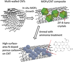
In our previous report, we have developed N-containing carbon from an in situ grown MOF/carbon nanotube (CNT) hybrids. Reference Ge, Yang, Wang, Zhou, De Marco, Chen, Zou and Zhu17 The multi-walled carbon nanotubes (CNTs) were applied as the high conductivity skeleton, while the N-containing MOFs were used to form continuous layers on the CNTs and create abundant catalytic sites on the CNT skeleton without sacrificing structural integrity and electrical conductivity. The derived catalysts had an N content of 5.38% and exhibited comparable ORR activity to commercial Pt/C electrocatalysts. In this study, to further improve the ORR performance, the additional ammonia treatment was applied after the pyrolysis of the MOF/CNT composite (Fig. 1). The graphitic N content and surface area have been further increased, exhibiting higher activity and stability than 40 wt% Pt/C electrocatalysts.
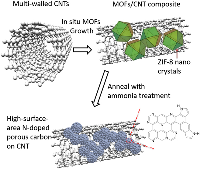
FIG. 1. Schematic diagram of the method to synthesize high-surface-area N-doped carbon from ZIF/CNT composites.
II. EXPERIMENTAL DETAILS
A. Material synthesis
1. Synthesis of carbon nanotubes and ZIF-8 composites
The multiwalled carbon nanotubes were supplied by Tsinghua University, China, with its purity exceeding 95 wt%, and the external diameter of CNTs is in the range of 10–30 nm. The inner diameters are around one third of the corresponding external diameters. The orientation of the carbon layers is parallel to its axis in a typical CNT.
Before synthesis of ZIF-8/CNTs composites, the carboxyl-modified CNTs were prepared by acid treatment based on the method reported elsewhere. Reference Liu, Rinzler, Dai, Hafner, Bradley, Boul, Lu, Iverson, Shelimov, Huffman, Rodriguez-Macias, Shon, Lee, Colbert and Smalley18 For instance, CNTs (0.5 g) were sonicated in a 300 mL mixture of concentrated H2SO4 (98 vol%)/HNO3 (70 vol%) (3:1 in volume) for 3 h at 60 °C. Subsequently, the sample was washed with deionised water and filtered, followed by drying under vacuum. The ZIF-8/CNTs composites were also prepared under the same solvothermal procedures of ZIF-8, with the exsistence of predispersed CNTs. Reference Ge, Yang, Wang, Zhou, De Marco, Chen, Zou and Zhu17 More specifically, 120 mg-treated CNTs were dispersed into Hmim (0.649 g) in 20 mL methanol by repeating the sonication and stirring process prior to adding the Zn(NO3)2·6H2O methanol solution. For comparison, different amounts (5.1, 14.7, 50.6, and 240.3 mg) of CNTs were used. Then the dispersion was rapidly added into a solution of Zn(NO3)2·6H2O (0.2933 g) with 20 mL methanol. The mixture slowly turned milky in color, and the stirring continued for 15 min. Then the mixture was put into a 100 mL Teflon-lined autoclave and later into an oven where it was heated at 90 °C for 6 h. After the hydrothermal reaction, the synthesized CNTs/ZIF-8 composites were separated by centrifugation and washing with methanol for three times; finally the product was dried at 80 °C under vacuum. The synthesized composite was noted as ZIF-CNT.
2. Pyrolysis of CNT-ZIF composites and ammonia treatment
Firstly, the CNT-ZIF powders were carbonized in a tube furnace under Ar atomosphere. The furnace was heated to 150 °C for 1 h. Subsequently, pyrolysis of the ZIF-8 and composites was performed in Ar at 1000 °C for 3 h with a heating rate of 10 °C/min. After that, the furnace was cooled down to 800 °C under a cooling rate of 5 °C/min by a temperature program of the furnace, and then 10 vol% NH3 was injected for 0.5 h. After annealing, the furnace was cooled to room temperature in this atmosphere of NH3 and Ar. As a comparison, pyrolyzation of CNT-ZIF under the same condition was also conducted followed by natural cooling in Ar without ammonia treatment. The ZnO residues in the derived carbon were removed by HCl solution washing. Reference Jiang, Liu, Lan, Kuratani, Akita, Shioyama, Zong and Xu19 The obtained sample was named as N-ZCNT.
3. Fabrication of thin film electrode
A suspension of the electrocatalyst was prepared by mixing N-ZCNT catalysts (5 mg) in ethanol (0.25 mL) and Nafion solution (5 wt%, 25 μL) for 20 min of sonication. Then 5 μL of suspension was drop cast onto a glassy carbon disk electrode (4 mm diameter, 0.126 cm2 area) and left to dry in a glass jar.
B. Electrochemical measurements
Voltammetric experiments were performed with a Biologic VMP2/Z multichannel potentiostat. RRDE voltammograms were obtained in an O2 (99.999%)-saturated 0.1 M KOH electrolyte at 5 mV/s at room temperature using a platinum wire counter electrode and an Ag|AgCl (3 M NaCl) reference electrode. All potentials in this study were iR-corrected to compensate for the influence of solution resistances, which were calculated using the following equation:
 $$E\left( {iR{\rm{ ‐ corrected}}} \right) = E - iR\quad ,$$
where i is the current and R is the uncompensated ohmic electrolyte resistance measured via high-frequency AC impedance spectroscopy in O2-saturated 0.1 M KOH. The double-layer background current obtained in N2-saturated cells was subtracted from the ORR currents. Electrode kinetic data was calculated according to the well-known Koutecky–Levich equation:
 $${1 \over i} = {1 \over {{i_{\rm{k}}}}} + {1 \over {{i_{\rm{d}}}}} = {1 \over {nFAk{C^{\rm{o}}}}} + {1 \over {0.62nFAD_{{{\rm{O}}_2}}^{2{\rm{/}}3}{v^{ - 1/6}}{C^{\rm{o}}}{\omega ^{1/2}}}}\quad ,$$
where n is the overall transferred electron number, F is the Faraday constant, C
o is the saturated concentration of oxygen in 0.1 M KOH (1.14 × 10⁻⁶ mol/cm3), A is the geometric area of the electrode (cm2), ω is the rotating rate (rad/s), ${D_{{{\rm{O}}_2}}}$
is the diffusion coefficient of oxygen (1.73 × 10⁻⁵ cm2/s), v is the kinetic viscosity of the solution (0.01 cm2/s), and k is the rate constant for oxygen reduction. i
k is the mass-transport-corrected kinetic ORR current density, and i
d represents the limiting current density. RRDE voltammograms were used to identify the electron transfer number (n) and peroxide yield (X, percentage of H2O2 relative to total products). The ring potential was set at 0.4 V versus Ag|AgCl (3 M NaCl), which is considered to be sufficiently positive to induce complete H2O2 decomposition.
${D_{{{\rm{O}}_2}}}$
is the diffusion coefficient of oxygen (1.73 × 10⁻⁵ cm2/s), v is the kinetic viscosity of the solution (0.01 cm2/s), and k is the rate constant for oxygen reduction. i
k is the mass-transport-corrected kinetic ORR current density, and i
d represents the limiting current density. RRDE voltammograms were used to identify the electron transfer number (n) and peroxide yield (X, percentage of H2O2 relative to total products). The ring potential was set at 0.4 V versus Ag|AgCl (3 M NaCl), which is considered to be sufficiently positive to induce complete H2O2 decomposition.
C. Materials characterization
The JEOL JSM 7001 (JEOL Ltd., Tokyo, Japan) operated at 10 kV with an Oxford SDD EDS X-ray spectrometer (Oxford Instruments, Abingdon, United Kingdom) was used to characterize material morphology. High-resolution transmission electron microscopy (HRTEM) was performed on a JEOL JEM-2100 microscope (JEOL Ltd., Tokyo, Japan), with accelerating voltages of 200 kV. The Micromeritics TriStar 3020 (Micromeritics, Norcross, Georgia) was used to obtain nitrogen gas physisorption isotherms of samples at −196 °C after degassing the samples for 12 h at 150 °C. The corresponding specific surface areas (S g) were calculated using the Langmuir equation at a relative pressure (P/P θ) of 0.005–0.05. Total pore volumes (V p) were evaluated at relative pressures (P/P θ) close to unity, with the micropore volume obtained using the Dubinin–Radushkevich method by taking data points in the range of P/P 0 of 0.01–0.3. The Fe residue contents in the catalysts were determined by Varian Vista Pro ICP-OES (Varian, Inc., Palo Alto) using a Sturman-Masters spray chamber and a V-groove nebulizer.
Raman spectra were obtained by using an ALMEGA Dispersive Raman instrument (Thermo Nicolet, Waltham, Massachusetts) with a 10 mW Ar laser (wave length of 514 nm). A 100× objective lens was used to focus an illuminated spot of ∼2 μm diameter on the sample. XPS was performed on a PHI-560 ESCA (Perkin Elmer, Waltham, Massachusetts) using a near-monochromatic Mg Kα excitation source at 15 kV. The C 1s peak at 284.6 eV was applied as an internal standard to correct charging of the samples. Quantitative analysis was performed using the CASAXPS software (Casa Software Ltd., Teignmouth, United Kingdom) after the Shirley background subtraction. The best fits of peaks were obtained using mixed 30% Gaussian–Lorentzian line shapes. The full width at half maximum values was fixed at a maximum limit of 1.5 eV for all peaks in the curve fitting procedure.
III. RESULTS AND DISCUSSION
A. Characterisation of electrocatalysts
Figure 2 shows the morphology of ZIF-CNT composites before the pyrolysis. The observed grape-branched morphology can be attributed to the strong interaction between ZIF-8 and CNTs. Most of the ZIF-8 crystals covered the surface of carbon nanotubes by taking advantage of the oxygen functional groups as the nucleation sites. Reference Hermes, Schröder, Chelmowski, Wöll and Fischer20–Reference Yang, Ge, Rudolph and Zhu23 As can be seen in Fig. 2(b), the crystal sizes of ZIF-8 on the CNTs are between 10 and 50 nm. Most of the particles formed a continuous layer and were smaller than ZIF-8 synthesised at the same condition, indicating the confinement growth mode on CNTs. Reference Ge, Yang, Wang, Zhou, De Marco, Chen, Zou and Zhu17 Some ZIF-8 particles with a size of ∼100 nm can also be observed, which could be attributed to the extra ZIF-8 sources and lack of nucleation sites. The homogeneity of ZIF-8 growth on CNT depends on the surface area of CNT and the amount of oxygen functionality on CNTs, which can be tuned by the CNT ratio in the ZIF-8 synthesis. As shown in our previous article, Reference Ge, Yang, Wang, Zhou, De Marco, Chen, Zou and Zhu17 the CNT loading ratios up to 42 wt% were carried out to screen the optimal ZIF-8 dispersion and composite morphology. By control of the amount of CNTs in the hydrothermal synthesis, the controllable location and dispersion of ZIF-8 crystals were observed (Fig. S1). At a low CNT ratio (<27 wt%), more individual growth of ZIF-8 can be observed due to the insufficient surface support and nucleation sites. At a higher CNT ratio (>27 wt%), smaller ZIF-8 particles can be observed on the CNT due to the enrichment of nucleation sites. However, the high surface coverage of the CNT inhibits further attachment of ZIF-8, leading to the heterogeneity of the ZIF-8 particle size. The optimal ZIF dispersion morphology was observed with ZIF-8 crystals with most of the particles wrapping onto the external surface of CNTs at 27 wt% CNT loading, which was selected for pyrolyzing and further ammonia treatment in this study.

FIG. 2. SEM (a) and TEM (b) images of ZIF-CNT composites.
Figure 3 displays the morphology of the derived carbon composite after pyrolyzation and ammonia treatment. The rough surface can be observed in the treated N-ZCNT samples [Fig. 3(a)]. Compared to ZIF-8 grown on CNTs, the carbonization process reduced the particle size and formed ZIF-8 wrapping on the carbon nanotubes. By comparing to the morphology of ZIF-8 on CNT [Fig. 2(b)], it is clear that rhombic dodecahedral ZIF-8 crystals have led to distorted-shaped carbon particles with large amounts of nanopores after pyrolysis [Fig. 3(b)]. By comparing the SEM images of the pyrolyzed sample without ammonia treatment (Fig. S2), the ammonia treatment had a negligible impact on the morphology. The integrity and tubular structure of carbon nanotubes were maintained after carbonization and ammonia treatment at high temperature. As can be seen in Fig. 3(c), the thickness of the porous carbon layer on the CNTs is 5–10 nm, showing multilayer graphene sheets stacked in parallel. As can be seen in Fig. S2, the ammonia treatment has little influence on the carbon nanotube X-ray diffraction patterns (002, 100, and 004) which only illustrate three crystalline peaks at 2θ = 26°, 43°, and 54° of carbon materials. No diffraction peak of Zn residues was observed thereby confirming the efficiency of acid washing.

FIG. 3. SEM (a) and TEM images of N-ZCNT (b), carbonized ZIF-8 on carbon nanotubes (c).
Figure 4 demonstrates the XPS spectrum of N-ZCNT. The absence of the Zn 2p peaks at 1021 eV in the XPS spectra suggests the removal of Zn residues by acid washing. By taking advantage of the N content in ZIF-8 and ammonia treatment, the nitrogen doping content can reach 5.4%. N heteratoms in the derived composite is made up of pyridinic N, pyrrolic N, graphitic N, and oxidized N. Compared to our previous results (N content of 4.58%) of the sample, without further ammonia treatment, Reference Ge, Yang, Wang, Zhou, De Marco, Chen, Zou and Zhu17 N-ZCNT displayed more graphitic N (approximately 1.35 at.%, BE (binding energy) = 401.0 eV) and pyridinic N (approximately 2.47 at.%, BE (binding energy) = 398.4 eV). The further increase of total N content after ammonia treatment should be attributed to the N doping on both CNT and porous carbon-derived ZIF-8. It may also suggest that the ammonia treatment can tune the N doping configurations derived from the N-containing organic linker of ZIF-8. The further improvement of total N and graphitic N contents in porous carbon composite is expected to boost the catalytic activity in ORR since the graphitic nitrogen has been hypothesized as the most active site compared to pyrrolic and pyridinic nitrogen. Reference Lai, Potts, Zhan, Wang, Poh, Tang, Gong, Shen, Lin and Ruoff24
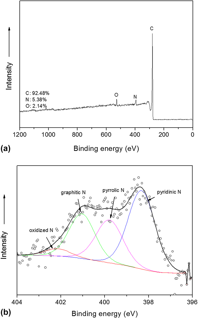
FIG. 4. XPS survey (a) and high-resolution (b) spectra of N 1s of N-ZCNT.
Since the trace impurity metal can contribute to the electrocatalyst activity, Reference Wang, Ambrosi and Pumera25 the iron impurity contents from ICP are also given and compared in Table I. As shown in Ref. Reference Li, Zhou, Wang, Xie, Liang, Wei, Idrobo, Pennycook and Dai2, further purification of the referenced carbon nanotubes-graphene catalyst and reduction in the iron content can lead to the reduction of catalytic activity. The iron residues in our catalyst also originate from the metal catalyst used in the CNT synthesis, while low iron content of the N-ZCNT electrocatalyst at 0.37 wt% is observed. Compared to carbon nanotubes-graphene catalyst (1.1 wt%2) in the literature, the N-ZCNT electrocatalyst with lower iron content still performs with higher activity, suggesting the positive roles of the derived catalyst structure and graphitic nitrogen.
TABLE I. The composition and pore information of synthesized N-ZCNT.

Figure 5 shows the nitrogen adsorption isotherm of the derived N-ZCNT, the Type II isotherm indicates the presence of both mesopores and micropores. This nitrogen-enriched product still exhibits a very high surface area (739 m2/g) and processes the mixture of micropores and mesopores, as summarized in Table I. The hierarchical porous structure of N-ZCNT, the excellent adhesion of porous carbon/CNTs, and the preserved graphitic structure in CNTs are expected to boost the oxygen diffusion and activity in ORR. Compared to the carbon product without ammonia annealing, Reference Ge, Yang, Wang, Zhou, De Marco, Chen, Zou and Zhu17 a slight increase in surface area and pore volume was observed. The minor drop in microporous volume can be assigned to the induced graphitic defects by ammonia treatment. As indicated in Fig. 6, the I D/I G value is 2.18, which is higher than that of the sample without ammonia treatment (I D/I G = 1.39). Reference Ge, Yang, Wang, Zhou, De Marco, Chen, Zou and Zhu17
FIG. 5. N2 adsorption isotherm of N-ZCNT.

FIG. 6. Raman spectrum of N-ZCNT.
B. Electrochemical performance of derived electrocatalysts
Figure 7 shows the comparison of ORR activities between N-ZCNT and 40 wt% Pt/C electrocatalysts measured by sweep voltammetry in O2 saturated 0.1 M KOH electrolyte using a RRDE at room temperature. The half-wave potential (E 1/2) of the N-ZCNT is 0.899 V with an E 1/2 positive shift of 18 mV compared to commercial Pt/C electrocatalysts (E 1/2 = 0.881 V). The incorporation of CNTs into the composite material can significantly increase the mesoporous volume with the hierarchical porous structure also facilitating oxygen diffusion during the ORR process. Reference Liang, Zheng, Chen, Liu, Hulicova-Jurcakova, Jaroniec and Qiao26,Reference Yang, Feng, Wang and Mullen27 Furthermore, the N-ZCNT catalyst shows a higher ORR onset potential of 1.05 V against Pt/C (1.02 V). The further increment of N content benefits the improvement of ORR activity compared to the untreated carbon products from the ZIF-CNT composite with a half-wave potential (E 1/2) of 0.887 V. Reference Ge, Yang, Wang, Zhou, De Marco, Chen, Zou and Zhu17 The Tafel curve of the N-ZCNT is shown in Fig. 7(b). The Tafel slope of N-ZCNT is 46 mV/dec, which is lower than that of commercial Pt/C electrocatalysts and some other advanced electrocatalysts. Reference Li, Zhou, Wang, Xie, Liang, Wei, Idrobo, Pennycook and Dai2,Reference Liang, Li, Wang, Zhou, Wang, Regier and Dai28,Reference Chung, Won and Zelenay29 A low value of the Tafel slope illustrates attainment of a high catalytic current density at low applied potentials, reflecting the high activity of the electrocatalyst. Due to this low value of the Tafel slope, the specific activity of N-ZCNT at 0.80 V is over 700 mA/cm2 that is much higher than that of the commercial Pt/C catalyst (∼114.4 mA/cm2). By comparing to the sample without ammonia treatment (49 mV/dec), Reference Ge, Yang, Wang, Zhou, De Marco, Chen, Zou and Zhu17 the further reduction of the Tafel slope in N-ZCNT indicates the effectiveness of boosting the total N and graphitic N content. The ORR pathways catalyzed by the N-ZCNT were also revealed by RRDE measurements [Fig. 7(c)], and the calculated peroxide yield of the N-ZCNT is less than 2.3% in the range from 0.85 to 0.4 V. The electron transfer number is 3.994 that approach the perfect 4-electron transfer for ORR, suggesting an ultrahigh ORR activity in this N-doped carbon hybrid electrocatalyst. Figure 7(d) displays the corresponding chronoamperometric response of the N-ZCNT electrode to evaluate the possible crossover and poison effects in the presence of methanol. Compared to the sharp decrease in current upon the addition of methanol observed by the commercial Pt/C electrode, N-ZCNT shows a stable chronoamperometric response, indicating the superior resistance of the poisoning crossover effect. As a whole, the N-ZCNT electrocatalyst exhibits higher ORR catalytic activity compared to the Pt/C electrocatalyst. The CNTs act as the skeleton to support the continuous thin layer of N-doped carbons and introduce the hierarchical porous structure and high surface area, facilitating the charge transfer and oxygen diffusion in ORR. A further improvement in the N content by following ammonia treatment can further increase the active sites on the derived catalysts.
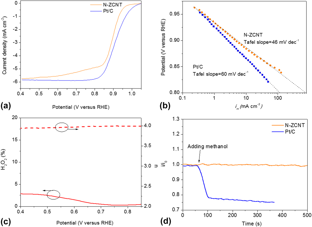
FIG. 7. (a) ORR current densities of glassy carbon (GC)-supported thin film N-ZCNT (0.72 mgcatalyst cm−2) and 40 wt% Pt/C electrocatalysts (80 μgPt cm−2) at 1600 rpm in O2-saturated 0.1 M KOH at 5 mV/s; (b) Tafel plots of N-ZCNT and Pt/C derived by the mass-transport correction of corresponding rotating ring disc electrode (RRDE) data; (c) Peroxide yield (H2O2, solid lines) and electron-transfer numbers (n, dash lines) during. (d) Chronoamperometric response at 0.95 V on N-ZCNT and Pt/C electrodes, respectively, in O2-saturated 0.1 M KOH (1600 rpm) before and after introduction of methanol.
IV. CONCLUSIONS
The grape-brunched shape of the nitrogen-doped carbon composite has been synthesized by in situ hydrothermal synthesis, followed by pyrolysis and ammonia treatment. The derived ORR electrocatalyst has hierarchical porous structures enriched with nitrogen, exhibiting superior ORR activity (a positive shift of +18 mV and a low Tafel slope of 46 mV/dec) and methanol tolerance compared to commercial Pt/C catalysts. The high-surface-area and thin graphitic N enriched carbon layer on the CNT skeleton favor the charge transfer, electrical conductivity, and mess diffusion in ORR. Nitrogen doping in the carbon composite can be achieved by the existing N-containing organic ligands with further adjustment of the facial ammonia treatment, favoring the boost of the active site for ORR. The additional ammonia annealing process contributes to the further increment of the surface area and N doping content, especially the increase of graphitic N. This facial treatment can play an important role in tuning the N content and species in MOFs-derived carbon electrocatalysts. The combination of MOFs and graphitic carbon materials offers an excellent platform for fabricating high-efficiency electrocatalysts for applications in many electrochemical reactions and systems.
Supplementary Material
To view supplementary material for this article, please visit https://doi.org/10.1557/jmr.2017.416.
ACKNOWLEDGMENTS
This work was supported by the Australia Research Council Future Fellowship (FT120100720). The authors acknowledge the facilities, and the scientific and technical assistance, of the Australian Microscopy & Microanalysis Research Facility at the Center for Microscopy and Microanalysis.


