


I. INTRODUCTION
Owing to their unprecedented chemical and physical properties, graphene has witnessed huge research activity in most areas of science and technology. The combination of their superlative mechanical, thermal, and electronic properties can be envisioned for not only a wide range of applications, but also a test bed for fundamental science and research work. Reference Soldano, Mahmood and Dujardin1,Reference Geim and Novoselov2 Researchers around the world have been intrigued by its unique combination of properties that makes them ideal candidates as advanced fillers in composite materials. In particular, properties of graphene have been envisaged as an ideal filler material in monolithic ceramics. This is because; despite the fact that monolithic ceramics are commonly known as a promising structural material with high stiffness, strength, and stability at high temperatures; they are still susceptible to brittleness, mechanical unreliability, and poor electrical conductivity. Reference Centeno, Rocha, Alonso, Fernández, Gutierrez-Gonzalez, Torrecillas and Zurutuza3–Reference Cho, Boccaccini and Shaffer7 In view of these limitations, ceramic matrix composites have been developed. Thanks to graphene's exceptional properties (Young's modulus of 1 TPa, breaking strength of 42 N/m, and in plane electrical conductivity of 107 S/m) Reference Gómez-navarro, Burghard and Kern8,Reference Singh, Joung, Zhai, Das, Khondaker and Seal9 incorporating graphene into ceramics has great potential to produce tough and electrically conductive ceramic composites which could solve a wider range of material related challenges in processing industries, aerospace, transportation, and military applications. Reference Gómez-navarro, Burghard and Kern8,Reference Koller10–Reference Choi and Awaji12 Nevertheless, processing of graphene based ceramic composites is complicated due to introduction of reinforcement particle at nanometric scale. Therefore, processing routes need to be modified carefully and validated thoroughly before producing graphene based ceramic composites. In this context, critical issues such as (i) homogenous dispersion of graphene in the ceramic matrix and (ii) interfacial bonding between graphene and ceramic matrix needs to be addressed since it directly affects the properties of the nanocomposites.
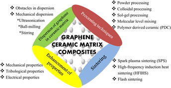
Whilst much of the emphasis has been intensifying on graphene based composites, comprehensive reviews on processing graphene based ceramic composites are still limited. Herein, the authors make an attempt to gather information from the early to the most recent developments regarding graphene based ceramic composites. More specifically, the paper is aimed at discussing in depth on three principle topics: (i) principles and techniques for graphene dispersion (ii) processing of graphene–ceramic composites and (iii) the effects of graphene fillers on the properties of the resultant composite. Figure 1 summarizes the topics which will be covered in this review paper.

FIG. 1. Graphical illustration of topics discussed in review.
II. WORLDWIDE RESEARCH ON GRAPHENE BASED COMPOSITES
The quality and quantity of work on graphene have attracted worldwide attention in the mere five year span upon its emergence. This is ascertained by the intensity and number of publications arising from various countries in the field of graphene. In fact, by the year 2020, graphene market will rise by a Compound Annual Growth Rate (CAGR) of 60%. Reference Vivek Dhand, Rhee and Kim13 As of today, research on graphene has been revolutionized in every discipline. A total of 174,521 articles was retrieved via Web of Science search tool for the syntax string 〈graphene〉 from the year 2000–2015. The publication trend on graphene reveals that the amount of research on graphene has increased exponentially from 90 articles in the year 2000 to 44,648 articles in the year 2015 (Fig. 2).
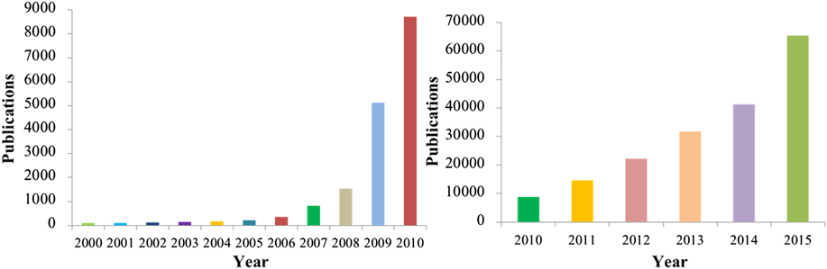
FIG. 2. Publication trend of graphene from the year 2000 to 2015.
From the bar chart (Fig. 2), it is evident that the future of graphene is very bright with high prospects. A refined analysis shows that the annual number of publications for graphene has been increasing dramatically and graphene's properties are likely to be exploited in the primary area of applications. In the last five years, materials science (no. of documents: 79,273) was the most researched area followed by chemistry (73,951), physics and astronomy (60,495), engineering (44,962), and energy (14,328). This indicates the importance of graphene research in various research areas across the world. In particular, the phenomenal properties (mechanical, thermal, and electrical) of graphene make it an ideal candidate as advanced filler material in ceramic composites. Researchers have envisaged taking advantage of these properties to produce tough and electrically conductive ceramic composites using graphene as reinforcing fillers. For example, ZrB2–graphene based ceramic composites can be exploited for use in the aerospace industry as high temperature barrier for space vehicle during the re-entry event. Reference Yadhukulakrishnan, Karumuri, Rahman, Singh, Kaan Kalkan and Harimkar14 These ultra-high temperature ceramic composites have been used as primal infrastructure for nose caps in space shuttles and military ballistic equipment. Some work has also been carried out on several other ultrahigh temperature ceramic composites such as carbides of tantalum (Ta), zirconia (Zr), hafnium (Hf), niobium (Nb), and borides of Hf, Zr, and titanium (Ti) respectively. Recently, Lahiri et al. introduced carbon nanotubes (CNTs) in TaC ceramics and proved that one can induce formation of multilayer graphene within host matrix upon spark plasma sintering. Reference Lahiri, Khaleghi, Bakshi, Li, Olevsky and Agarwal15 This phenomenon is important as it offers resistance to pullout, which results in high strength of material and delayed fracture. Another interesting study, demonstrated by Kim and Hong is the use of TiN–graphene composites as selective permeable membrane for hydrogen. Reference Kim and Hong16 They proposed the use of graphene with TiN owing to graphene's high resistance to oxidation and exceptional mechanical properties. Findings from their study revealed that high specific area of TiN–graphene membrane was due to nanoflake type of graphene used which enhanced hydrogen permeability on the membrane. These membranes can be revisited in future for implementation in high purity separation and filtration of chemicals, petroleum, and biomolecules by exploiting their pore size distribution, surface area, and elasticity.
III. DISPERSION OF GRAPHENE IN CERAMIC MATRIX
A. Obstacles in graphene dispersion
Quality of graphene dispersion in ceramic matrices significantly affects properties of the final composite produced. In an ideal situation, a fully densified ceramic composite with perfect graphene dispersion within the ceramic matrix whilst avoiding any graphene damage and agglomeration is required to achieve excellent performance of graphene–reinforced ceramic composites. Sizable amount of work has been done in the past decade to produce well dispersed graphene based ceramic composites. Reference Tapasztó, Tapasztó, Markó, Kern, Gadow and Balázsi17–Reference Chintapalli, Marro, Milsom, Reece and Anglada25
One of the major issues during the incorporation of graphene in ceramic matrices is the difficulty in obtaining uniform dispersion of the nanofillers owing to their tendency to agglomerate due to van der Waals forces. This is a consequence of high surface area and high aspect ratio of graphene; which is strongly undesirable. Reference Tkalya, Ghislandi, de With and Koning23,Reference Ma, Siddiqui, Marom and Kim26–Reference An, Simmons, Shah, Wolfe, Lewis, Washington, Nayak, Talapatra and Kar32 This critical disadvantage has driven the need to develop various techniques to improve dispersion of graphene to ensure efficient load transfer from ceramic matrix to nanofillers.
Amongst them is the use of dispersing agents or surfactants. Walker et al. have shown dispersion of graphene using a cationic surfactant (cetyl trimethyl ammonium bromide, CTAB); which occurs because hydrophobic graphene is attracted to hydrophobic tails of the surfactant which results in graphene that is covered in positively charged surfactant molecules. Reference Walker, Marotto, Rafiee, Koratkar and Corral33 Other studies have reported using polyethylene glycol (PEG), Reference Dusza, Morgiel, Duszová, Kvetková and Nosko34,Reference Kun, Tapasztó, Wéber and Balázsi35 1-methyl-2-pyrolidinone (NMP), Reference Liu, Fan, Li, Wang and Jiang36 3-aminopropyltriethoxysilane Reference Chen, Liu, Zhao, Wang, Wang, Jiang and Li37 and sodium dodecyl sulfate. Reference Yazdani, Xia, Ahmad and Zhu5 Results from these studies have demonstrated that the behavior of graphene follows the qualitative prediction of Derjaguin–Landau–Verwey–Overbeek (DLVO) theory. Based on the DLVO theory, stability of graphene in the ceramic suspension is based on the net balance of two pre-dominant forces; namely electrostatic repulsion that prevents and attractive Van der Waals forces that promote agglomeration. While in distilled water the high negative wall surface potential of graphene is capable of overwhelming Van der Waals attractions, addition of surfactants (ionic charges) gives rise to double layer formation, high surface potential, and strong electrostatic repulsion which counterbalances Van der Waals attraction and stabilizes graphene dispersion.
Uniform distribution of nanofillers within ceramic matrix ensures efficient load transfer and stress distributions from ceramic matrix to nanofillers, thus minimizing presence of stress concentration points. We postulate that stress concentration sites between grains invariably cause fracture to proceed from this point. In particular, a big piece of ceramic fails in a rapid and spectacular fashion due to a tiny crack. Herein, the various dispersion techniques will be discussed in the following sections.
B. Mechanical dispersion of graphene
1. Ultrasonication
Ultrasonication technique utilizes ultrasound energy to agitate particles in any solution. The principle is such that ultrasound propagates through a series of compression, which induce attenuated waves in the molecule of the medium it passes. Shear force due to this shockwave will “peel off” the individual nanoparticle located at the outer part of nanoparticle bundle or agglomerates, thus resulting in separation of individualized nanoparticles of the bundle. Reference Sahithi, Harshit, Mansi, Ganesh and Vijayakumar27 Ultrasonication in solvents and high power bath sonication are among the common primary step to produce homogenous and aggregate free dispersions. Reference Guo, Mao, Ouyang, Zhu, He, Lv, Liang, Ren, Chen and Zheng28
Wang et al. used ultrasonication to produce well dispersed graphite oxide (GO)–alumina composites. Reference Wang, Wang, Fan, Yan and Wei29 In their work GO and alumina suspension in water were prepared by ultrasonication in 100 mL water respectively by sonication for 30 min. Well-dispersed graphene–alumina composites were produced by adding GO drop wise to the prepared alumina suspension under mild magnetic stirring. The results showed that GO solution was well dispersed due to electrostatic repulsion and intramolecular dehydration occurring on the edges of GO, whereas alumina particles were also well dispersed in water solution with zeta potential value of 32 mV. However, flocculent precipitate was observed when GO was gradually added into the identical alumina suspension due to electrostatic attraction between GO and alumina particles. In a similar vein, recently Kim et al. revisited the technique used by Wang et al. where N,N-dimethylformamide (DMF) was used as a solvent to disperse expanded graphite via ultrasonication. Reference Kim, Lee, Oh, Yang and Lim38 While graphene dispersion is similar to previous studies, the use of un-oxidized graphene (which did not go through any oxidation or reduction process) in ceramic based composite materials has not been achieved in previous studies. In another study, Ivanov et al. dispersed graphene in 100 mL of deionized water and treated ultrasonically for 5 min at 100 W with a pulse mode of 3 s work and 1 s pause respectively. Reference Ivanov, Hussainova, Aghayan and Petrov39 After a series of steps, the final ceramic composites of the graphene solution and various ratios of partially stabilized zirconia (PSZ) consisted of very well dispersed and agglomerate-free graphene.
However, it should be noted that this technique is unfortunately hampered by aggressive and long sonication periods; especially when a probe sonicator was used. For example, extreme cases observed complete destruction of graphene layers and deterioration of nanotubes manifested by the reduction of nanofiller's aspect ratio, a direct effect of the breakage of agglomerates or conversion of nanotubes into nanofibers. Reference Gkikas, Barkoula and Paipetis30 The localized damage to graphene deteriorates both electrical and mechanical properties of the composite. Some researches have proposed carrying out sonication process in an ice bath to avoid overheating and defect formations on nanofiller surface.
2. Ball milling
Ball milling is a physical grinding method that is capable of breaking the materials into extremely fine powder. In this process, high pressure is generated locally from a collision that takes place among the small and rigid balls (e.g., ceramics, flint pebbles, and stainless steel) in the concealed container. The internal cascading effect of the balls will lead to a reduction in size of the material into a fine powder.
Ball milling of graphene in the presence of chemicals not only enhances its dispersability, but also provides a simple, cost-effective, and scalable process for production of few layer graphene (FLG) by combining ball milling with exfoliant. Reference Aparna, Sivakumar, Balakrishnan, Sreekumar Nair, Nair and Subramanian31 A simple high energy ball milling and combinatorial approach using strong exfoliant (1-pyrenecarboxylic acid) and common solvent (methanol) were able to produce few-layer graphene with distinctive Raman signature, x-ray diffraction crystallinity, and high conductivity values (6.7 × 10³ S/m). Reference An, Simmons, Shah, Wolfe, Lewis, Washington, Nayak, Talapatra and Kar32 In fact, various researchers have investigated the effect of ball milling on the dispersion of graphene/CNT. Reference Wu and Kim40–Reference Bastwros, Kim, Zhu, Zhang, Wang, Tang and Wang43 Pierard et al. investigated the effect of ball milling time on CNT structure; where milling time varied from 1 to 50 h while the milling amplitude was kept constant at 3000 vibrations per minute. Reference Pierard, Fonseca, Colomer, Bossuot, Benoit, Van Tendeloo, Pirard and Nagy44 The resulting images from transmission electron microscopy (TEM) revealed limited destruction of nanotubes during first 3 h of milling; progressive disruption of nanotubes was observed with increasing milling time until complete destruction after 50 h of milling. Besides, the increase in intensity of the D-bands with increasing ball-milling time ascertains progressive disruption and production of disordered carbon [Fig. 3(a)]. Similarly, Bastwros et al. studied the effect of different ball milling times on graphene quality within the alumina matrix. Reference Bastwros, Kim, Zhu, Zhang, Wang, Tang and Wang43 Qualities of samples were studied by performing Raman spectroscopy analysis. The authors used I D/I G ratio from Raman scans as a measure to detect the disordering and defect density in graphitic structure. From the Raman scans obtained, I D/I G value for sample after 90 min of ball milling increased from 1.1 to 1.4 that indicates disordering and defects in graphene structure [Fig. 3(b)]. The authors claimed that the amount of defects in graphene increased after ball milling due to the physical forces applied during the process.

FIG. 3. Effects of ball milling time on the structures of (a) CNTs Reference Pierard, Fonseca, Colomer, Bossuot, Benoit, Van Tendeloo, Pirard and Nagy44 and (b) graphene Reference Bastwros, Kim, Zhu, Zhang, Wang, Tang and Wang43 represented by Raman spectra. Reproduced from Refs. Reference Bastwros, Kim, Zhu, Zhang, Wang, Tang and Wang43 and Reference Pierard, Fonseca, Colomer, Bossuot, Benoit, Van Tendeloo, Pirard and Nagy44 with permission from Elsevier.
Ball milling process maximizes the load sharing and pullout effect of graphene as it strengthens interfaces between ceramic matrix and graphene. It is also a proven technique not only to disperse, but also reducing the number of stacked graphene layers within the matrix. However, few attempts have been carried out to study the effect of other influencing parameters such as ball amplitude, process time, and ball material. Since these parameters modulate graphene's final surface area, further studies concerning these parameters should be taken into consideration.
3. Stirring
Stirring is one of the most commonly used techniques for particle dispersion in liquid systems. The factors that influence the dispersion of graphene by stirring include the size and shape of the propeller, mixing speed, and duration of mixing. Reference Ma, Siddiqui, Marom and Kim26 Intensive stirring of graphene in ceramic matrix may result in relatively fine dispersion. In 2014, Rincon et al. established the route to produce laminates of Al2O3–YSZ–graphene based composite. Reference Rincón, Moreno, Chinelatto, Gutierrez, Rayón, Salvador and Borrell45 After a series of steps (including modified Hummer's method), the as-prepared mixtures of Al2O3–ZrO2–GO were kept under mechanical stirring for 20 min to achieve excellent homogenization, and produce materials with controlled microstructure. Similar stirring technique was used by Wu et al. to produce GO–ZrB2 ceramic composite. Reference Wu, Lv, Peng, He and Mu46 The results from SEM analysis indicate the presence of very stable ZrB2 between graphene stacks; which prevents graphene from rapidly restacking.
In a more recent study, Low et al. prepared GO films from graphite flakes via an improved Hummer's method. Reference Low, Lai and Abd Hamid47 The authors investigated the effect of stirring duration at a high speed of 1200 rpm on the formation of GO films. They studied the variation in transmittance value of functional group for GO sheet synthesized at different stirring durations using the FTIR instrument. This work suggests that transmittance value (intensity) broadened after 72 h of high-speed stirring; indicating the formation of high-yield large-area GO sheets. A disappointing fact of this technique is the tendency of graphene to re-agglomerate, due to various factors such as frictional contacts, elastic interlocking mechanisms, sliding forces, and weak attractive forces upon stirring. Reference Schmid and Klingenberg48 Besides, these agglomerations become spontaneous under static conditions.
Table I compares the characteristics of three common techniques used for the dispersion of graphene; which can be used as a general guideline to select the appropriate dispersion technique for the preparation of graphene/ceramic composites. It is, however noteworthy that there is no omnipotent tool to achieve perfect dispersion of different graphene in different ceramic matrices. Factors such as state of ceramic matrix, dimensions and content of graphene to be added, availability and suitability of dispersion techniques should be taken into consideration prior to selecting the best technique for graphene dispersion.
TABLE I. Characteristic comparison of various graphene dispersion techniques.
IV. PROCESSING OF GRAPHENE CERAMIC COMPOSITES
The desirable characteristics of graphene based ceramic composites depends on many factors such as phase homogeneity, fine particle size that promotes sintering, equiaxed shape to enhance packing and uniform distribution of graphene within the ceramic matrix. A key issue in assessing toughening mechanisms of these composites has been the difficulty in fabricating composites with well-controlled micro/nano-structures. Reference Wu and Kim40 Thus, suitable processing route is critical to obtain ceramic composites with desired properties. Today, there is a trend to develop more complex processing techniques of graphene based ceramic composites than the traditional powder processing route. They include colloidal processing, sol–gel, PDC route, and molecular level mixing. The following subsections present the classifications of major processing techniques to fabricate graphene based ceramic composites.
A. Powder processing
Powder processing route has been very commonly applied in ceramic system and were the first processing route considered at the early stages of graphene–ceramic composite fabrication. Different matrices that have been used with this processing route include alumina, zirconia, silicon nitride, and silica. Reference Miranzo, Ramírez, Román-Manso, Garzón, Gutiérrez, Terrones, Ocal, Osendi and Belmonte4,Reference Yazdani, Xia, Ahmad and Zhu5,Reference Tapasztó, Tapasztó, Markó, Kern, Gadow and Balázsi17,Reference Fan, Wang, Li, Li, Sun, Chen, Chen and Jiang55–Reference Liu, Yan, Reece and Jiang65 In this technique, graphene is deagglomerated via ultrasonication/stirring prior mixing with a ceramic mixture using conventional ball milling or high energy ball milling. The most common dispersant for graphene has been ethanol or NMP whereas milling time ranged from 3 to 30 h to produce well dispersed composites. Since processability of graphene is easier in comparison to CNTs, powder processing route is a promising approach to create graphene based ceramic composites.
Kun et al. synthesized fine particles of graphene and Si3N4 using this technique by milling in highly efficient attritor mill to form the composite. Reference Kun, Tapasztó, Wéber and Balázsi35 The milling process was performed at high rotation speed of 3000 rpm for 4.5 h. The authors reported that graphene particles conferred a cumulative effect in improving the mechanical attributes of composites and decreased the agglomeration quotient of graphene in the ceramics during mixing. A similar technique was demonstrated by Miranzo et al. using SiC powder and graphene, milled in ethanol for 2 h and spark plasma sintered at a heating rate of 133 °C/min under 4 Pa at 1850 °C. Reference Miranzo, Ramírez, Román-Manso, Garzón, Gutiérrez, Terrones, Ocal, Osendi and Belmonte4 In another study, Tapaszto et al. produced Si3N4 composites reinforced with single walled carbon nanotubes (SWCNTs), multi-walled carbon nanotubes (MWCNTs), and few layer graphene using attritor milling. Reference Tapasztó, Markó and Balázsi66 Small angle neutron scattering experiments and SEM images confirm that graphene can be dispersed more efficiently in the ceramic matrix in comparison to CNTs. In 2014, Michalkova et al. compared homogenization of graphene nanoplatelets (GNP) in Si3N4 matrix using various methods such as attritor milling, ball milling, and planetary ball milling. Reference Michálková, Kašiarová, Tatarko, Dusza and Šajgalík59 The best results were obtained for ceramic composites prepared using planetary ball milling although all composites displayed a decrease in mechanical properties compared to monolithic Si3N4.
In conclusion, powder processing route offers unprecedented opportunities to significantly reduce complexity, cost, and time to synthesize graphene–ceramic composites in comparison to colloidal processing. Besides, this technique has successfully created a homogenous dispersion of the second phase (graphene) in ceramic composites. However, it should be noted that the distribution of high surface area and high aspect ratio filler in the absence of driving force impede graphene to de-agglomerate and distribute from ceramic powder particle surface into the bulk of the mixture.
B. Colloidal processing
Colloidal processing refers to the route of producing intimate dispersion of graphene and ceramic matrix to produce composites with homogenous microstructure and controllable properties based on colloidal chemistry. In this route, colloidal suspensions are usually used to coat graphene with ceramic particles by modifying the surface chemistry, stabilizing suspensions, and reducing repulsion between graphene that facilitates the homogenous dispersion of graphene throughout ceramic matrix grains. It is noteworthy that dispersion of graphene is established by manipulating surface chemistry of two phases during low temperature processing; wherein this dispersion is retained even after sintering. Typically, similar solvent is preferred for both graphene and ceramic powders to ensure uniform dispersing medium. Moreover, slow mixing (magnetic stirring/ultrasonication) is important to favor uniform dispersion of graphene into the ceramic matrix. Another requirement for colloidal processing is surface modification of both graphene and ceramic matrix; which is achievable via direct functionalization (i.e., oxidation) or by using surfactants that generate electric charges. In most cases, modification involves generation of charges between ceramic powders and graphene; a process known as heterocoagulation. To date, many literature have demonstrated heterocoagulation as a very effective route for producing well dispersed graphene–ceramic composites. Reference Centeno, Rocha, Alonso, Fernández, Gutierrez-Gonzalez, Torrecillas and Zurutuza3,Reference Yadhukulakrishnan, Karumuri, Rahman, Singh, Kaan Kalkan and Harimkar14,Reference Wang, Wang, Fan, Yan and Wei29,Reference Walker, Marotto, Rafiee, Koratkar and Corral33,Reference Rincón, Moreno, Chinelatto, Gutierrez, Rayón, Salvador and Borrell45,Reference Fan, Jiang and Kawasaki56
The first true study of heterocoagulation process to produce graphene–alumina based ceramic composites was reported by Wang et al. in 2011. Reference Wang, Wang, Fan, Yan and Wei29 In their work, GO and alumina suspension was prepared by ultrasonication in water separately. Then, GO was added dropwise into the alumina suspension under stirring conditions. Centeno et al. demonstrated a similar technique where graphene–alumina based ceramic composites were fabricated by adding GO dropwise into alumina suspension under mechanical stirring while pH of 10 was maintained. Reference Centeno, Rocha, Alonso, Fernández, Gutierrez-Gonzalez, Torrecillas and Zurutuza3 Similar to the previous studies, Fan et al. prepared GNS–Al2O3 composites via colloidal processing route; where GO colloid and alumina colloid were added dropwise into each other. Reference Fan, Jiang and Kawasaki56 In another study by Walker et al. graphene–Si3N4 composites were successfully produced via colloidal processing route. Reference Walker, Marotto, Rafiee, Koratkar and Corral33 Cetyl trimethyl ammonium bromide (CTAB) was used as a cationic surfactant to produce positive charges on both ceramic and graphene surfaces. 1 wt% CTAB was used to disperse both graphene and Si3N4 to develop electrostatic repulsive forces on the surfaces, to obtain good dispersion of graphene within the ceramic matrix. Although a variety of colloidal processing routes have been described, there is still a lack of quantitative information on graphene and ceramic matrix to precisely compare the dispersion potential of each route in terms of agglomerate size in solutions to quantitatively evaluate the dispersion homogeneity of various routes.
C. Sol–gel processing
Sol–gel processing route provides an alternative route to create an intimate dispersion of graphene in ceramic composites. In this method, graphene is dispersed in molecular precursor solution (e.g., tetra methyl ortho silicate (TMOS)) that undergoes condensation reaction to generate green body for subsequent consolidation. Later, suspension of TMOS and graphene will be sonicated to obtain a uniformly dispersed sol. Gelation is initiated by adding catalyst (e.g., acidic water) which promotes hydrolysis and leads to formation of composite gels upon condensation at room temperature. This technique has been utilized mainly to create silica nanocomposite. For example, Watcharotone et al. prepared graphene–silica film to be used as transparent conductors, where TMOS was added to the Hummers-modified graphene oxide (GO) suspension to create a stable suspension. Reference Watcharotone, Dikin, Stankovich, Piner, Jung, Dommett, Evmenenko, Wu, Chen, Liu, Nguyen and Ruoff67 GO (highly oxygenated graphene) was used instead of graphene since GO has good solubility in polar solvents in comparison to graphene. Reference Narasimman, Vijayan and Prabhakaran68 Another work by DiMaio et al. reported tetra ethyl ortho silicate (TEOS) as the molecular precursor solution to produce silica composites for nonlinear optic application with low CNT content (0.25 wt%). Although sol–gel reaction is ought to provide route to good dispersions, agglomeration in the precursor suspensions has been problematic. Reference Cho, Boccaccini and Shaffer7 Nevertheless, this technique only requires liquid precursors; which eases the preparation of doped materials or well-dispersed composites by dissolving or suspending materials in liquid phase. Reference Zheng, Feng, Zhen, Huang and Zhan69
D. Polymer derived ceramics (PDC)
Polymer derived ceramic (PDC) route is used to produce composite materials that are difficult to be processed via conventional powder technology. In this technique, common preceramic polymers such as poly(silazanes), poly(siloxanes), and poly(carbosilanes) are processed and shaped using conventional polymer forming techniques that are very well established in the polymer industry such as polymer infiltration pyrolysis (PIP), injection molding, coating from solvent, extrusion, and resin transfer molding (RTM). Reference Colombo, Mera, Riedel and Sorarù70 Upon processing, objects made from preceramic polymers can be converted into ceramic components by heating to temperatures that are sufficient to consolidate elements in the polymer structure into a ceramic. One of the fundamental advantages of PDC route is the versatility of the materials that can easily be shaped in form of fibers or bulk composites. Besides, PDCs exhibits excellent thermo–mechanical properties such as temperature stabilities up to 1500 °C. In fact, recent studies show that temperature stability up to 2000 °C can be achieved if the preceramic polymers contains boron. Reference Riedel, Mera, Hauser and Klonczynski71 Furthermore, PDCs have also been considered as additive free ceramic materials that possess excellent oxidation and creep resistance. In particular, PDC technique is suitable for graphene–ceramic composites since desired dispersion of nanofiller (graphene) can be produced in liquid phase precursors prior pyrolysis. Reference Porwal, Grasso and Reece72,Reference Ionescu, Francis and Riedel73
One of the earliest study utilizing PDC route was reported by Ji et al., where GO was dispersed in polysiloxane (PSO) precursor liquid and SiOC followed by crosslinking and pyrolysis at 1000 °C in Argon gas to produce graphene nanosheets (GNS)–SiOC. Reference Ji, Li, Feng, Su, Wen, Feng and Hou74 Their results show that discharging capacity of GNS–SiOC composite was higher in comparison to monolithic SiOC because of increasing number of electrochemically active sites. Another technique in PDC route involves the infiltration of PDC resin from solution into pre-existing fabricated ceramic green body, which was demonstrated by Cheah et al. in 2013. Reference Cheah and Chin75 They first fabricated green bodies by gel casting the ceramic suspension on PDMS soft molds. These green bodies were then infiltrated with PDC resin (RD-212a) before sintering at 1200 °C. In their study, the infiltration of the pre-ceramic resin into presintered ceramic has successfully sealed the pores.
However, there are several concerns in using this processing route such as considerable shrinkage ratio and volume decrease due to material change and gas loss during thermal treatment. Reference Sarin, Mari, Llanes and Nebel76 Shrinkage also causes cracking while gas loss may leave poorly distributed pores behind. In some cases, retaining the as-formed shape throughout the thermal treatment stage becomes difficult since polymers become less viscous. In view of these limitations, extensive experimental or modeling data are necessary to understand how PDC route may affect the microstructural features and composition of graphene based ceramic composites.
E. Molecular level mixing
Molecular level mixing is another route used to produce ceramic–graphene composites by utilizing a molecular-level-mixing process. In this route, functionalized graphene in a solvent will be mixed with ceramic salt; which is then converted into ceramic particles by heat treatment or other processing methods. Reference Lee, Koo, Jin, Kim and Hong77,Reference Hwang, Yoon, Jin, Lee, Kim, Hong and Jeon78 This route enables molecular level coating of ceramic particles with graphene. The key advantages are excellent dispersion of graphene in the ceramic matrix and good interfacial bonding of ceramic–graphene at molecular level. As a consequence of good interfacial bonding between ceramic matrix and graphene, molecular level combination of the two components (ceramic & graphene) necessary to enhance property of the composite may be relatively easier to achieve.
In 2014, Lee et al. reported molecular level mixing to produce alumina–GO composite with different wt% of GO. Reference Lee, Koo, Jin, Kim and Hong77 In their study, GO was dispersed in distilled water by sonication to form a GO suspension. Alumina nitrate precursor salt [Al(NO3)3·9H2O] was added to this suspension and stirred for 12 h by magnetic stirring. The solution was then vaporized at 100 °C and dried powders were oxidized at 350 °C hot air to produce alumina particles. The powders were further processed by ball milling for 12 h to obtain well-dispersed alumina–GO powders. In the first stage, aluminum nitrate was thermally decomposed to Al ions while hydroxyl and carboxylic groups present on the surface of GO react with Al ions at the molecular level. This results in heterogeneous nucleation of Al ions on GO surface. Coating of Al ions on surface of GO avoids agglomeration of GO flakes. Interestingly enough, the authors examined Al–O–C bonding via FT-IR analysis and interface area of reduced GO–alumina matrix using TEM analysis; which are strong evidences of molecular level mixing process. Due to the characteristic microstructure, the GO–alumina composite showed enhanced strength, hardness, and fracture toughness superior to monolithic. The schematic representation for fabricating reduced GO–alumina composite by molecular level mixing process is depicted in Fig. 4.
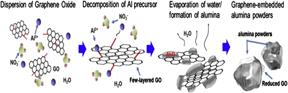
FIG. 4. Schematic representation for fabricating reduced GO–alumina composite by molecular level mixing process. Reproduced from Ref. Reference Lee, Koo, Jin, Kim and Hong77 with permission from Elsevier.
Previous work of graphene–ceramic composites was mostly based on conventional powder metallurgy route; which resulted in composites exhibiting lower than expected mechanical properties because graphene is prone to agglomeration due to van der Waals forces. Reference Wang, Wang, Fan, Yan and Wei29 Besides, sol–gel process have been proven to disperse graphene within ceramic matrix; however; interface between graphene and ceramic matrix were not strong. Reference Dimaio, Rhyne, Yang, Fu, Czerw, Xu, Webster, Sun, Carroll and Ballato79 Therefore, although molecular level processing remains to be explored in detail, it is nonetheless plausible to claim that this route is the most promising process to obtain homogenous dispersion of graphene and strong interfacial strength.
V. COMPACTION AND CONSOLIDATION
Early studies of graphene reinforced ceramic composites were rather limited due to thermal stability of graphene >600 °C. Reference Jeong, Lee, Jin, Kim, Bae and Lee80 While ceramics start to densify upon sintering at temperature >1000 °C, challenges arises to incorporate graphene which has low thermal stability at temperature in excess of ∼600 °C. Insights into conventional sintering (e.g.,: pressure-less sintering) revealed that this technique require long processing time and high temperature to prepare fully dense ceramics. A disappointing fact is that, this leads to grain growth and simultaneous degradation of graphene in the ceramic matrix. Reference Inam, Yan, Reece and Peijs18 As such, to overcome the limitations in ceramic–graphene composites, novel sintering techniques are continuously being exploited with the aim of lowering sintering temperature and shortening dwelling time. For example, Hot Pressing (HP) and Hot Isostatic Pressing (HIP) have focused on sintering ceramics at lower temperatures by application of pressure whereas Spark Plasma Sintering (SPS) and microwave sintering focus on sintering ceramics at both lower temperature and shorter dwell times by application of both pressure and electric field to obtain high heating rates.
A. Spark plasma sintering (SPS)
SPS is considered as a relatively new; high temperature-low dwell time powder consolidation technique that has been successfully implemented to create fully dense ceramics. Reference Munir, Anselmi-Tamburini and Ohyanagi81–Reference Hulbert, Jiang, Dudina and Mukherjee83 SPS involves simultaneous application of pressure and electric current through a graphite die containing ceramic powders to be sintered. The pulsed current assist in densification of ceramics via creep mechanism; unlike conventional sintering techniques that relies on diffusion and mass transport phenomena across grain boundaries during long periods of dwelling time. Therefore, SPS has been useful for investigating the sintering behavior of carbon based fillers (graphene/CNTSs) reinforced ceramic composites; since isothermal conditions can be achieved rapidly enabling densification to be studied over wide range of densities. Reference Milsom, Viola, Gao, Inam, Peijs and Reece84
Other key advantages of SPS technique is the in situ reduction of GO to graphene in a single step without requiring any additional steps and alignment of graphene in host matrix. Reference Centeno, Rocha, Alonso, Fernández, Gutierrez-Gonzalez, Torrecillas and Zurutuza3 Graphene—a two dimensional material naturally aligns in a direction perpendicular to applied pressure. Centeno et al. used Raman spectroscopy to ascertain the alignment of graphene in alumina matrix. Reference Centeno, Rocha, Alonso, Fernández, Gutierrez-Gonzalez, Torrecillas and Zurutuza3 Raman scans on surface of graphene–alumina composite in parallel and perpendicular directions during SPS shows that I D/I G ratio (the ratio of D and G peaks) was higher for sample surface perpendicular to pressing direction (I D/I G = 1.13) than the sample surface parallel to pressing direction (I D/I G = 0.83). Typically, the I D/I G ratio in Raman spectra can be used to quantify defects in graphene. Figure 5 shows the Raman spectra of composites taken at different directions. The percentage of graphene surface exposed to Raman scans were considerably higher in orientation parallel to the pressure direction applied in SPS leading to a higher Raman intensity; while in the perpendicular orientation the percentage of the graphene surface exposed to the measurement were considerably lower.
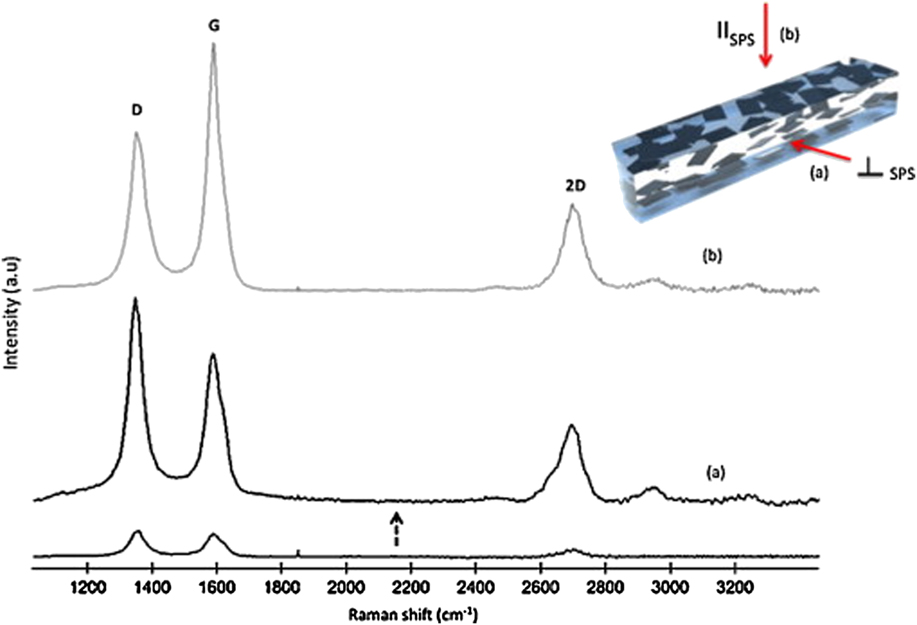
FIG. 5. Raman spectrum of the Al2O3–graphene composite at two different orientations: (a) perpendicular to pressure direction applied in SPS (b) parallel to pressure direction applied in SPS. Reproduced from Ref. Reference Centeno, Rocha, Alonso, Fernández, Gutierrez-Gonzalez, Torrecillas and Zurutuza3 with permission from Elsevier.
One of the first studies on physical properties of Si3N4 ceramics densified via SPS was made by Walker et al. in 2011. Reference Walker, Marotto, Rafiee, Koratkar and Corral33 In this work, preliminary densification investigation on SPS parameters revealed that; (i) for dwell time of 5 min; density increased with increasing temperature (1500–1600 °C) and remained constant up to 1700 °C (ii) for dwell time of 2 min; greater densification was achieved resulting in 100% theoretical density at 1650 °C (Fig. 6). This is important as it demonstrates a better understanding of maintaining high density at the lowest possible temperature and shortest amount of time at temperature. Shortly afterward, SPS was revisited by many authors to densify ceramics owing to its advantages. Reference Centeno, Rocha, Alonso, Fernández, Gutierrez-Gonzalez, Torrecillas and Zurutuza3,Reference Chintapalli, Marro, Milsom, Reece and Anglada25,Reference Ramirez and Osendi58,Reference Román-Manso, Sánchez-González, Ortiz, Belmonte, Isabel Osendi and Miranzo60,Reference Liu, Yan and Jiang64,Reference Liu, Yan, Reece and Jiang65,Reference Shin and Hong85,Reference Porwal, Tatarko, Grasso, Khaliq, Dlouhý and Reece86
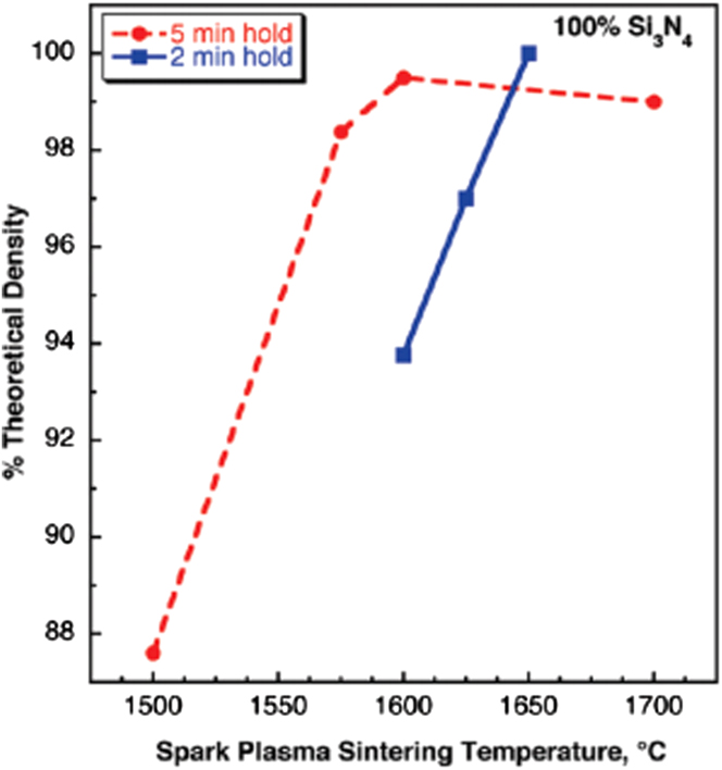
FIG. 6. Density of Si3N4 as a function of sintering temperature for two different holding times (5 and 2 min); 100% of theoretical density obtained at ∼1650 °C for 2 min hold. Reproduced from Ref. Reference Walker, Marotto, Rafiee, Koratkar and Corral33 with permission from American Chemical Society.
B. High-frequency induction heat sintering (HFIHS)
In 2015, Kwon et al. demonstrated that ZrO2–graphene composites can also be densified via high-frequency induction heat sintering (HFIHS). Reference Kwon, Lee and Shon87 HFIHS focusses on sintering ceramics over very short sintering times (<2 min) through the simultaneous application of induced current and high pressure (Fig. 7). Role of the current in HFIHS is two-folded; (i) intrinsic contribution of current to mass transport (ii) fast heating attributed by Joule heating at contact points. The composites produced via this technique were dense; with relative density as high as 96%. Recently, Ahmad et al. reported similar sintering technique (HFIHS) in processing conditions of 1500 °C sintering temperature, 60 MPa pressure, and 3 min holding time yields Al2O3–graphene composites with near theoretical densities (>99%). Reference Ahmad, Islam, Abdo, Subhani, Khalil, Almajid, Yazdani and Zhu88 While this sintering technique is not earth shattering, it is still plausible as it represents a new sintering approach to that of SPS, HP, or HIP. By careful modification or optimization of process parameters, it may be possible to push the relative density values to near 100% by increasing the heating rates. The challenge is to avoid degradation or property deterioration of graphene within the ceramic composite and to find a cost effective way to achieve this.
FIG. 7. Schematic representation of the equipment for HFIHS. Reproduced from Ref. Reference Kwon, Lee and Shon87 with permission from Elsevier.
C. Flash sintering
A more recent technique of sintering ceramics is via flash sintering. It occurs when electrical field is applied to a heated ceramic compact. At critical combination of field and temperature, power surge occurs (“flash event”) resulting in sintering completion in few seconds. Reference Todd, Zapata-Solvas, Bonilla, Sneddon and Wilshaw89 The growing interest in flash sintering arouse after publication from Cologna et al. in 2010. Reference Cologna, Rashkova and Raj90 In their study, an initial voltage was applied to zirconia powder compact whilst it is slowly heated in conventional furnace. At 850 °C, “flash event” occurs and over a few seconds, specimens are sintered to near full density. This finding was explained by local Joule heating of grain boundaries, which on one hand promotes grain-boundary diffusion (kinetic effect) and at the same time restricts grain growth (thermodynamic effect). The smaller grain size and higher temperature at grain boundaries work synergistically to enhance rate of sintering. In a recent study, Grasso et al. used flash sintering to sinter ZrB2 ceramics. Reference Grasso, Yoshida, Porwal, Sakka and Reece91 The ceramic were densified up to 95% in 35 s under an applied pressure of 16 MPa. In comparison to conventional SPS technique, the newly developed flash sintering resulted in unprecedented energy and timesaving of approximately 95% and 98% respectively. However, this technique is limited to conductive ceramic materials. Since GCMC is conductive due to the presence of graphene, flash sintering can be exploited in future studies to densify ceramic–graphene composites.
Table II summarizes processing route of graphene based ceramic composites reported in literature. It should be noted that since graphene based composites are emerging materials, many studies are conducted to devise newer processing routes that will produce graphene-based composites with unique structures for specialty end applications.
TABLE II. Processing routes of graphene based ceramic composites as reported in literature.
VI. MATERIAL PROPERTIES
Graphene exhibits exceptional mechanical properties; monolayer graphene was reported to be the strongest material ever existed with Young's Modulus of 1 TPa and reported breaking strength of 42 N/m. Reference Gómez-navarro, Burghard and Kern8 The excellent properties of graphene alongside with its low density, high surface area, and high aspect ratio enables graphene to be a desirable material for reinforcement in ceramic composite materials. However, dispersion is the foremost important requirement to produce strong and tough graphene based ceramic composites.
The techniques used for dispersion of graphene have been discussed in Sec. III. Good dispersion of graphene in ceramic matrix ensure availability of large filler surface area for bonding with the host matrix and prevent aggregation of the filler that acts as stress concentrator which is detrimental to mechanical performance of composite. Reference Liu and Wagner96 Thus, graphene dispersion can be influential largely on the mechanical properties of composites. Although there is sizable volume of literature on the mechanical properties of graphene reinforced ceramics, little open literature have been hitherto compiled the very recent research and findings in this area. Therefore, the recent progress and findings on the mechanical properties of graphene reinforced ceramics are introduced here.
A. Evaluation of fracture toughness
The dream prosecution of graphene properties has been the driving force for the ceramic community to study the reinforcement mechanism in graphene based ceramic composites. Vickers Indentation (VI), single etched notched beam (SENB), and Chevron notch are the most commonly used techniques to measure fracture toughness and exemplify the toughening mechanisms induced by graphene in ceramic composites. VI is the nontraditional method that utilizes a Vickers indenter to make a contact impression on polished and flat specimen surface. This technique has been widely used and advantageous in terms of ease of use without requiring any precrack elaboration, mechanical testing equipment, and proper fixtures. However, VI has been criticized by traditional fracture mechanics community due to unreliability, inaccuracy, and imprecision. Reference Quinn and Bradt97,Reference Ponton and Rawlings98 More importantly, this technique has not been included in any form of international standards for determination of fracture toughness including American society for testing and materials (ASTM) and European committee for standards (CEN). 99,100 VI also does not account for the absolute values of fracture toughness as it a measure of material toughness locally under complex stress field. Reference Ponton and Rawlings98,99 Nevertheless, many studies have repeatedly used VI method to determine fracture toughness, K IC of graphene based ceramic composites. Reference Yamamoto, Omori, Hashida and Kimura24,Reference Chintapalli, Marro, Milsom, Reece and Anglada25,Reference Walker, Marotto, Rafiee, Koratkar and Corral33,Reference Wang, Padture and Tanaka101 Majority of these studies used the formula developed by Anstis et al.
 $${K_{{\rm{IC}}}} = 0.16{\left( {{E \over H}} \right)^{{1 \over 2}}}\left( {{P \mathord{\left/ {\vphantom {P {\mathop {{C_{\rm{O}}}}\nolimits^{{3 \mathord{\left/ {\vphantom {3 2}} \right. \kern-\nulldelimiterspace} 2}} }}} \right. \kern-\nulldelimiterspace} {\mathop {{C_{\rm{O}}}}\nolimits^{{3 \mathord{\left/ {\vphantom {3 2}} \right. \kern-\nulldelimiterspace} 2}} }}} \right)\quad ,$$
where E is the modulus of the composites, H is the measured hardness, P is the applied load, and C O is the radical crack length or Shetty equation as below; Reference Dusza, Morgiel, Duszová, Kvetková and Nosko34,Reference Kvetková, Duszová, Hvizdoš, Dusza, Kun and Balázsi92
 $${K_{{\rm{ICInd}}}} = 0.089{\left( {{{H.P} \mathord{\left/ {\vphantom {{H.P} {4l}}} \right. \kern-\nulldelimiterspace} {4l}}} \right)^{0.5}}\quad ,$$
where K IC is the fracture toughness, P is the load for indentation, H is the hardness, and l is crack indentation length.
On the other hand, SENB method has been claimed as one of the formal test procedures available to measure fracture toughness. Reference Quinn, Sundar and Lloyd102 This technique has single-well shaped precrack, good loading configuration and accurate stress intensity factor solution in comparison to VI method. The advantages have led to recognition and approval by the International Organization for Standards (ISO). 103,104 SENB method measures fracture toughness for bulk under the crack opening mode. Reference Sheldon and Curtin105 Therefore, SENB method is recommended where absolute fracture toughness values are required. In recent studies regarding graphene reinforcement effect in ceramic composites, determination of the fracture toughness using SENB is more often than VI due to the accuracy and fruitful discussions about the testing method. Reference Yazdani, Xia, Ahmad and Zhu5,Reference Cho, Boccaccini and Shaffer7,Reference Ahmad, Cao, Chen, Zhao, Kennedy and Zhu22,Reference Chen, Bi, Yin and You61,Reference Liu, Yan and Jiang64,Reference Liu, Yan, Reece and Jiang65,Reference Gogotsi, Galenko and Ozerskii106 In all studies mentioned above, SENB method was considered a standard method for measuring fracture toughness of advanced ceramic materials. The appealing main features of this technique such as uniform loading on a straight crack front and its ability to characterize R-curve of ceramics have been useful to analyze the dependence of fracture toughness with crack front size.
Another well-established technique to measure fracture toughness is the Chevron-notch method. In Chevron-notch bend test, K IC is typically determined by loading the sample at predetermined displacement rate in a test machine. K IC is then calculated from existing expressions for stress intensity factor in terms of maximum load observed and specimen geometry. Reported advantages of this technique are simplicity of loading under difficult conditions (elevated temperatures or in reactive environments), reproducibility of results and small amount of material required. Reference Chuck, Fuller and Freiman107 Despite these advantages, several studies have shown the formation of unstable crack propagation during loading. In a recent study by Porwal et al. they investigated the effect of graphene concentration on fracture toughness of alumina ceramics by using both Chevron notch and micro-indentation method. Reference Porwal, Tatarko, Grasso, Khaliq, Dlouhý and Reece86 Fracture toughness of the composite reinforced with 0.8 vol% graphene improved by ∼40% as measured by micro-indentation and ∼25% as measured by Chevron notch method. Authors claimed that indentation method measures toughness value locally and is not a reliable tool for measuring fracture toughness of high graphene (vol%) composites.
B. Toughening and crack mechanism
The intensity of reinforcement effects depends solely on bonding and graphene dispersion throughout the ceramic matrix. Toughening mechanism proposed in graphene reinforced ceramic composites are crack deflection due to load transfer and crack bridging due to graphene pullout. All these mechanisms are crucial to be microstructurally characterized for fruitful discussions.
In 2013, Centeno et al. reported that 0.22 wt% of graphene loading in alumina prepared by colloidal method has led to 50% increment in fracture toughness; attributed to the crack bridging phenomena. Reference Centeno, Rocha, Alonso, Fernández, Gutierrez-Gonzalez, Torrecillas and Zurutuza3 In other work by Dusza et al. 1 wt% graphene–Si3N4 composites by hot isostatic pressing were prepared; in which the hardness and fracture toughness of composites reinforced with different types of graphene; namely multilayer graphene, exfoliated GNP and nanographene platelets were compared. Reference Dusza, Morgiel, Duszová, Kvetková and Nosko34 Graphene platelets were found to induce porosity in samples. As a result of this, both hardness and fracture toughness values were lower in comparison to composites reinforced with multilayer graphene.
In a similar vein, Kun et al. prepared and characterized Si3N4 based nanocomposites reinforced with different amounts of carbon reinforcement in the form of multilayer graphene, GNP and nanographene platelets. Reference Kun, Tapasztó, Wéber and Balázsi35 The results was in good agreement with Dusza et al., where graphene platelets induced porosity in samples that leads to lower bending strength and module of elasticity value in comparison to composites reinforced with multilayer graphene. Most of the studies on graphene based ceramic composites have shown that toughening mechanisms originated from pull-outs, crack deflection, crack branching, and crack bridging (Figs. 8 and 9).

FIG. 8. Various toughening mechanisms in graphene based ceramic composites (a) crack deflection and bridging Reference Ahmad, Islam, Abdo, Subhani, Khalil, Almajid, Yazdani and Zhu88 (b) crack deflection Reference Liu, Yan and Jiang64 (c) crack branching Reference Kvetková, Duszová, Hvizdoš, Dusza, Kun and Balázsi92 (d) and (e) GNS pullouts. Reference Chen, Bi, Yin and You61

FIG. 9. TEM images representing (a) distribution of Al2O3 nanoparticles over graphene nanosheets (GNS) and (b) GNS anchoring interaction with the base matrix grains. Reproduced from Ref. Reference Ahmad, Islam, Abdo, Subhani, Khalil, Almajid, Yazdani and Zhu88 with permission from Elsevier.
Ramirez et al. discussed the toughening mechanism in graphene–Si3N4 using a well-established model for reinforcement in ceramic composites. Reference Ramirez and Osendi58 The assumptions made were (i) GNP/GO were aligned in direction perpendicular to pressing direction in SPS (ii) graphene in ceramic matrix are in residual tension die to mismatch in thermal expansion coefficient of Si3N4 and graphene (iii) since graphene are in residual tension in Si3N4 matrix, fracture toughening due to graphene pull-out were not considered. This assumption is contradictory to experimental evidence; where many authors reported improvement in fracture due to graphene pull-out. Reference Chen, Bi, Yin and You61,Reference Liu, Yan, Reece and Jiang65,Reference Kvetková, Duszová, Hvizdoš, Dusza, Kun and Balázsi92 The improvement in toughness due to failure of graphene in wake zone was evaluated using equation below;
 $$\Delta {G_{\rm{c}}} = 2f\int_0^{t = S} {t{\rm{d}}u + {{4f{\Gamma _{\rm{i}}}d} \over {\left( {1 - f} \right)R}}}$$
 $$=\; {{f{S^2}R\left[ {{{\left( {{\lambda _1} + {\lambda _2}\left( {{d \mathord{\left/ {\vphantom {d R}} \right. \kern-\nulldelimiterspace} R}} \right)} \right)}^2} - {{\left( {{E_{\rm{f}}}{{{e_{\rm{T}}}} \mathord{\left/ {\vphantom {{{e_{\rm{T}}}} S}} \right. \kern-\nulldelimiterspace} S}} \right)}^2}{{\left( {{\lambda _3} + {\lambda _4}\left( {{d \mathord{\left/ {\vphantom {d R}} \right. \kern-\nulldelimiterspace} R}} \right)} \right)}^2}} \right]} \over {Ef\left( {{\lambda _1} + {\lambda _2}\left( {{d \mathord{\left/ {\vphantom {d R}} \right. \kern-\nulldelimiterspace} R}} \right)} \right)}} + {{4f{\Gamma _{\rm{i}}}d} \over {\left( {1 - f} \right)R}}\quad ,$$
where f is filler volume, S is the strength of filler, R is the filler radius, E
f is the elastic modulus of fiber, e
T is the misfit strain, and Γi is the interface fracture energy. λ
i
coefficients depend on filler volume fraction and ratio between fiber and elastic modulus of fiber. The first term in the equation is attributed to toughening due to crack bridging while the second term is associated with debond surface energy. Authors converted the toughness data to critical strain energy release rate (G
c) using the expression ${G_{\rm{I}}} = {{\mathop {{K_{\rm{I}}}}\nolimits^2 } \over E}$
and compared to data plotted using equation above. Authors found good correlation between experimental and theoretical data for GNP composites. They explained crack bridging to be the dominant toughening mechanism in GNP–Si3N4 composites. However, crack bridging becomes invalid for high loading of graphene due to formation of 3-dimensional inter-connected network of GNP which controls failure of composites.
${G_{\rm{I}}} = {{\mathop {{K_{\rm{I}}}}\nolimits^2 } \over E}$
and compared to data plotted using equation above. Authors found good correlation between experimental and theoretical data for GNP composites. They explained crack bridging to be the dominant toughening mechanism in GNP–Si3N4 composites. However, crack bridging becomes invalid for high loading of graphene due to formation of 3-dimensional inter-connected network of GNP which controls failure of composites.
Some promising mechanical results have been reported in a work by Walker et al. where an improvement of 235% in fracture toughness with only 1.5 vol% loading of GNS in Si3N4 matrix via aqueous colloidal processing method. Reference Walker, Marotto, Rafiee, Koratkar and Corral33 Some unexpected toughening mechanisms were observed for these composites. For example, cracks were not able to propagate through graphene walls and were arrested. Thus, the cracks were forced to deviate around the graphene sheets. This toughening mechanism is comparatively new in contrast to what has been observed previously.
A relatively new approach to incorporate graphene into a ceramic composite was reported by Porwal et al., where Al2O3–graphene composite was prepared using liquid phase exfoliation of graphene and dispersed them drop wise into Al2O3 matrix via ultrasonication and powder processing route, resulting in 40% increment in fracture toughness with only 0.8 vol% graphene added. Reference Porwal, Tatarko, Grasso, Khaliq, Dlouhý and Reece86 The aforementioned processing route appears advantageous as it solves the problem of producing good quality graphene without affecting its properties as in the case of Hummer's method. A breakthrough however came in a recent work by Yazdani et al. where Al2O3 nanocomposites reinforced with hybrid GNTs [GNP and CNTs] were prepared via a combination of wet dispersion and probe sonication technique, with increment in fracture toughness from 3.5 MPa m0.5 to 5.7 MPa m0.5 at hybrid addition of 0.5 wt% GNP and 1 wt% CNTs respectively. Reference Yazdani, Xia, Ahmad and Zhu5 This was accompanied by improvement in strength from 360 MPa to 424 MPa. They attributed the large reinforcement values to CNTs that attach to GNP surfaces and edges during the mixing process which assisted in deagglomeration and homogenous dispersion within the matrix. Toughening mechanism was attributed to the change in fracture mode from inter-granular in monolithic Al2O3 to blurry and glaze-like trans-granular mode in Al2O3 reinforced graphene composites.
Another interesting study by Kim et al. was to compare the mechanical properties of Al2O3 reinforced with un-oxidized graphene, GO and reduced GO respectively. Reference Kim, Lee, Oh, Yang and Lim38 Their findings suggested that the best results were obtained for un-oxidized graphene–alumina composites. The improvement in mechanical properties were related to less defect concentration in un-oxidized graphene flakes; ≈48% in fracture toughness, ≈28% in flexural strength, and ≈95% in wear resistance. Crack bridging was considered as the key toughening mechanism in the ceramic composite. They also investigated the effect of graphene size (≈100, 20, and 10 µm respectively) on fracture toughness of graphene–alumina composite and best results were attainable for graphene flakes with lateral size of ≈20 µm. Graphene flakes of ≈100 µm produced structural defects while toughening mechanisms such as crack bridging were less dominant when smaller flakes (≈10 µm) were used.
In an ideal situation, external load applied to graphene–ceramic composites should be transferred to the graphene, allowing them to take major share of the load. The efficiency of load transfer depends on the interfacial bonding of ceramic and graphene. In nanofiller reinforced ceramic, high strength of reinforcing fillers is important because once matrix crack is initiated; load will be transferred from the matrix to fillers during the initiation of crack. If the matrix–fillers adhesion is weak, the initiated crack will be deflected along the matrix–filler interface, leaving the fillers intact; thus toughening the composite material. However, if matrix is too strong, matrix crack penetrates through the fiber resulting in brittle composites as exemplified by monolithic ceramics. Reference Porwal, Grasso and Reece72
It should also be noted that in almost all studies; mechanical properties of graphene reinforced ceramic composites do not show proportional improvement with increasing graphene content. The reasons for this phenomenon are two-folded; (i) increase in porosity with increasing graphene content and (ii) overlapping/agglomeration of graphene. Pores acts as fracture initiation sites upon indentation load. Upon agglomeration of graphene, more pores are likely to be formed between agglomerated graphene platelets and ceramic matrix interface. The presence of these pores inevitably reduces contact area of ceramic matrix with graphene platelets and initiates cracks in which stresses are released in an inefficient way. For example, if a crack propagates and meets the graphene platelets, it is arrested and deflected in plane. Such crack deflection mechanism creates a complex pathway to release stress which helps to increase toughness of ceramic composite. Reference Liu, Yan, Reece and Jiang65 In the presence of pores, the contact area of graphene and ceramic is reduced. Besides, pores also weaken the interfacial friction during graphene pullout from the ceramic matrix. As such agglomeration of graphene platelets leads to degradation of strengthening and toughening mechanisms of graphene in their host matrix. Reference Michálková, Kašiarová, Tatarko, Dusza and Šajgalík59 Table III summarizes the mechanical properties of graphene based ceramic composites reported in literature.
TABLE III. Effect of graphene (G) addition on mechanical properties of ceramic composites.
a When loading was reported in volume percent, the density of bulk graphite (2.2 g/cm3) was used to convert to a weight percent loading.
C. Tribological behavior
A recent emphasis of graphene based ceramic composites has been on the tribological behavior such as wear and friction properties. Tribological properties of graphene based ceramic composites are expected to be improved in comparison to monolithic ceramics since graphene—a carbon material is a very good lubricant by itself due to its hexagonal structure.
Reference Berman, Deshmukh, Sankaranarayanan, Erdemir and Sumant109
Most authors have reported using ball on disc apparatus to study these properties.
Reference Kim, Lee, Oh, Yang and Lim38,Reference Hvizdoš, Dusza and Balázsi57,Reference Ahmad, Islam, Abdo, Subhani, Khalil, Almajid, Yazdani and Zhu88,Reference Belmonte, Ramírez, González-Julián, Schneider, Miranzo and Osendi94,Reference Li, Xie, Li, Huang, Huang, Zhao and Zheng110
The wear rate is typically calculated using the equation $W = {V \over {LF}},$
where W is specific wear rate, V is the worn volume, L is the sliding distance, and F represents the loading force during experiment. Coefficient of friction will be calculated by measuring the tangential forces during the test.
$W = {V \over {LF}},$
where W is specific wear rate, V is the worn volume, L is the sliding distance, and F represents the loading force during experiment. Coefficient of friction will be calculated by measuring the tangential forces during the test.
In a study by Hvizdoš et al. tribological properties of Si3N4–graphene composites was measured using the ball on disc method. Reference Hvizdoš, Dusza and Balázsi57 The findings suggested that coefficient of friction is independent on types of graphene used (exfoliated graphene platelets, nano-graphene platelets, and multilayer graphene); indicating perfect embedment of graphene in the Si3N4 matrix without taking part in the lubrication process. For wear resistance, 60% improvement was observed in Si3N4 matrix reinforced with 3 wt% graphene. Furthermore, comparison between wear resistance of Si3N4–graphene and Si3N4–CNT composites and found that graphene based composites were more wear resistant in comparison to CNT based composites for the same filler loading. Similar group of authors also studied the tribological behavior of Si3N4–graphene composites at moderate temperatures of 300, 500, and 700 °C demonstrating increasing proportional relationship between coefficient of friction and wear rate with increasing temperature. Reference Balko, Hvizdoš, Dusza, Balázsi and Gamcová93
Belmonte et al. investigated the effect of different loads (50, 100, and 200 N) on tribological behavior of Si3N4–graphene composites using the ball on disc method. Reference Belmonte, Ramírez, González-Julián, Schneider, Miranzo and Osendi94 The outcome indicates that both coefficient of friction and wear rates are inversely proportional to load. Similar study was performed by Li et al. in 2014 for zirconia–graphene composites with similar observations as Belmonte et al. where both coefficient of friction and wear rate of ceramic composite decreased with increasing load, 29% reduction in coefficient of friction, and 50% reduction in wear rate in comparison to pure zirconia coatings. Reference Li, Xie, Li, Huang, Huang, Zhao and Zheng110
In a more recent study by Yazdani et al. in 2015, they measured tribological performance of graphene/CNT hybrid reinforced Al2O3 composites by using ball on disc method. Reference Yazdani, Xia, Ahmad and Zhu5 According to the authors, Al2O3 composites consisting of (0.5 wt% GNP + 0 wt% CNT) and (0.3 wt% GNP + 1 wt% CNT) showed remarkable 70 and 80% reduction in wear rate; 23 and 20% reduction in coefficient of friction values respectively against monolithic Al2O3 for load of 15 N. Excellent coordination between GNP and CNT's led to great wear resistance properties of the composite. GNP played a vital role in formation of tribofilm on worn surface by exfoliation whereas CNT lead to improvement in fracture toughness and prevented grain from being pulled out during the tribological test.
VII. ELECTRICAL PROPERTIES AND PERCOLATION THRESHOLD
Volume conductivity higher than 10−10 S/cm for electrically conducting composites is classified as an important group of relatively inexpensive materials for a range of engineering applications. Reference Zhang, Dehghani-Sanij and Blackburn111,Reference Grossiord, Loos, Regev and Koning112 From virtually the moment graphene was discovered it was expected that they would display superlative electrical and thermal properties by analogy to graphite. It had been long known that graphite had an in plane electrical conductivity of 107 S/m and thermal conductivity of 5300 W/mK. Reference Singh, Joung, Zhai, Das, Khondaker and Seal9,Reference Balandin, Ghosh, Bao, Calizo, Teweldebrhan, Miao and Lau113 Thus, graphene is expected to be in a class of their own in terms of high electrical and thermal conductivities.
Electrically conducting behavior of ceramics with conducting fillers such as graphene can be explained using the percolation theory (Fig. 10). Percolation threshold is the condition referred to the critical filler content where measured electrical conductivity increases significantly to several orders of magnitude due to the formation of continuous electron/conducting paths. Electron paths do not exist below the percolation transition range; thus concentration of conducting filler must be above the percolation threshold to achieve conducting networks in the ceramics. Electrical conductivity experiences saturation plateau when multiple electron paths exist above the percolation transition range. This phenomenon can be explained by the change in nanofiller concentration based on the scaling law;
 $${\sigma _{\rm{c}}} = {\sigma _{\rm{o}}}{\left( {\emptyset - {\emptyset _{\rm{c}}}} \right)^t}\quad ,$$
where ${\emptyset _{\rm{c}}}$
and σo are the conductivity of composite material and nano-filler (graphene) respectively.
${\emptyset _{\rm{c}}}$
and σo are the conductivity of composite material and nano-filler (graphene) respectively. $\emptyset$
is the volume fraction of graphene,
$\emptyset$
is the volume fraction of graphene, ${\emptyset _{\rm{c}}}$
is the percolation threshold and t is the universal critical exponent revealing the dimensionality of the conducting system. In comparison to systems with spherical (graphene agglomerates) conducting fillers, the onset of percolation in fiber or “stick like” (flakes and platelets) systems takes place at a lower
${\emptyset _{\rm{c}}}$
is the percolation threshold and t is the universal critical exponent revealing the dimensionality of the conducting system. In comparison to systems with spherical (graphene agglomerates) conducting fillers, the onset of percolation in fiber or “stick like” (flakes and platelets) systems takes place at a lower $\emptyset$
of conducting filler.
Reference Balberg and Binenbaum114
Even at low filler concentrations, graphene fillers may be in direct contact with each other owing to their high aspect ratios. This results in macroscale conductive pathways through the entire ceramic composite. For uniformly dispersed particles,
$\emptyset$
of conducting filler.
Reference Balberg and Binenbaum114
Even at low filler concentrations, graphene fillers may be in direct contact with each other owing to their high aspect ratios. This results in macroscale conductive pathways through the entire ceramic composite. For uniformly dispersed particles, $\emptyset$
for onset of percolation threshold decreases with increasing aspect ratio (L/D) of graphene.
Reference Hashemi and Weng115
$\emptyset$
for onset of percolation threshold decreases with increasing aspect ratio (L/D) of graphene.
Reference Hashemi and Weng115
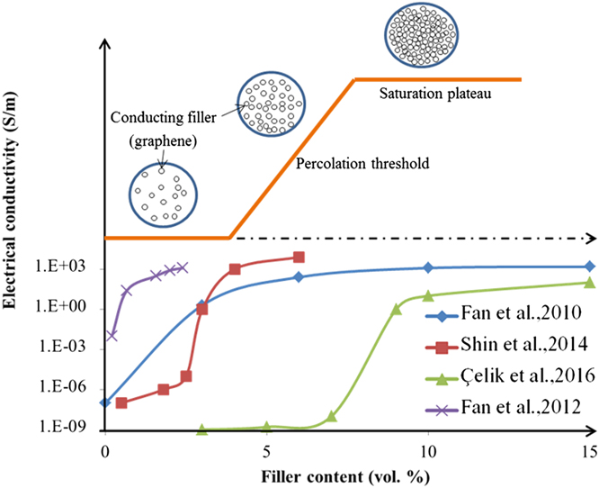
FIG. 10. Electrical conductivity and percolation phenomenon as a function of filler volume fraction in graphene based ceramic composites. Reference Fan, Wang, Li, Li, Sun, Chen, Chen and Jiang55,Reference Fan, Jiang and Kawasaki56,Reference Shin and Hong85,Reference Çelik, Çelik, Flahaut and Suvaci116
One of the earliest studies on percolation threshold for graphene reinforced ceramic composites was carried out by Fan et al. in year 2010. Reference Fan, Wang, Li, Li, Sun, Chen, Chen and Jiang55 Al2O3–graphene composites were prepared by spark plasma sintering with 0–15 vol% graphene. They demonstrated that percolation threshold for the ceramic composite was at 3 vol%. The electrical conductivity increased with increasing graphene loading; reaching a value of 5709 S/m for 15 vol% graphene. The increase in conductivity was explained by the increase in number of charge carriers across the composites.
In later study by Fan et al., colloidal processing was used for preparation of well dispersed GO and alumina composite powders, where GO was reduced to graphene via SPS processing. Reference Fan, Jiang and Kawasaki56 This study has improved upon their previous study; resulting in a threshold of 0.38 vol% lower than 3 vol% reported previously. The electrical conductivity was 1000 S/m for only 2.35 vol% loading of graphene. A breakthrough, however came when the hall coefficient reversed its sign from positive to negative; with increasing graphene loading revealing a change in major charge carrier. This was ascertained by measuring value of Seebeck coefficient, which also changed from positive to negative. The improvement in electrical conductivity was attributed to good dispersion and high quality of graphene used whereas the positive Hall coefficient was due to doping of graphene by the alumina matrix. In another study by Centeno et al., low percolation thresholds of 0.22 wt% witnessed increase in conductivity up to 8 orders of magnitude in comparison to unreinforced alumina. Reference Centeno, Rocha, Alonso, Fernández, Gutierrez-Gonzalez, Torrecillas and Zurutuza3 The authors reported that increase in graphene loading above percolation threshold resulted in increase in electrical conductivity which was attributed by increase in inter sheet connections that led to conductivity improvement along the a–b graphene planes.
Electrical conductivity of an insulator/conductor binary mixture (σm) can also be expressed as a function of filler volume fraction (V h) by the general effective media (GEM) equation Reference McLachlan117 ;
 $${{\left( {1 - {V_{\rm{h}}}} \right)\left( {\mathop {{\sigma _{\rm{l}}}}\nolimits^{{1 \mathord{\left/ {\vphantom {1 t}} \right. \kern-\nulldelimiterspace} t}} - \mathop {{\sigma _{\rm{m}}}}\nolimits^{{1 \mathord{\left/ {\vphantom {1 t}} \right. \kern-\nulldelimiterspace} t}} } \right)} \over {\mathop {{\sigma _{\rm{l}}}}\nolimits^{{1 \mathord{\left/ {\vphantom {1 t}} \right. \kern-\nulldelimiterspace} t}} \;+\; A\mathop {{\!\sigma _{\rm{m}}}}\nolimits^{{1 \mathord{\left/ {\vphantom {1 t}} \right. \kern-\nulldelimiterspace} t}} }} + {{{V_{\rm{h}}}\left( {\mathop {{\sigma _{\rm{h}}}}\nolimits^{{1 \mathord{\left/ {\vphantom {1 t}} \right. \kern-\nulldelimiterspace} t}} - \mathop {{\sigma _{\rm{m}}}}\nolimits^{{1 \mathord{\left/ {\vphantom {1 t}} \right. \kern-\nulldelimiterspace} t}} } \right)} \over {\mathop {{\sigma _{\rm{h}}}}\nolimits^{{1 \mathord{\left/ {\vphantom {1 t}} \right. \kern-\nulldelimiterspace} t}} \;+\; A\mathop {{\!\sigma _{\rm{m}}}}\nolimits^{{1 \mathord{\left/ {\vphantom {1 t}} \right. \kern-\nulldelimiterspace} t}} }} = 0\quad {\rm{where\ }}A = \left( {1 - {V_{{\rm{h,c}}}}} \right)\mathop {{V_{h,c}}}\nolimits^{ - 1} \quad ,$$
where σl and σh are the conductivities of the low and high conductivity phases, respectively, V h,c is the percolation threshold. The exponent t is a parameter dependent on shape and orientation of filler. Thus, t can be treated as phenomenological parameter typical of conductivity of a given composite. Reference McLachlan117 GEM equation is advantageous over conventional percolation threshold model owing to the data analysis close to percolation threshold. Ramirez et al. studied the effect of GPL loading above their percolation threshold (12 wt% and 15 wt%) on the electrical conductivity via conductive scanning force microscopy and GEM equation. Reference Ramirez, Garzón, Miranzo, Osendi and Ocal118 They reported that graphene concentration was directly proportional to the conductivity of ceramic composite. In addition, electronic response and final microstructure of the composite were due to the stiffness and aspect ratio that leads to self-orientation of GPL and lying on a–b plane during SPS. Besides, highly anisotropic nature of graphene reinforced ceramic composites lead to differences in transport activation energy that determines the different current values measured under the same conditions for parallel and perpendicular orientations. In 2012, the group of researchers extended their study using Si3N4 matrix reinforced with up to 20 vol% graphene platelets. Reference Ramirez, Figueiredo, Miranzo, Poza and Osendi119 They reported electrical conductivity of 40 S/m with the preferential orientation of graphene platelets in the ceramic matrix. In the direction perpendicular to the SPS pressing axis, electrical conductivity was an order of magnitude higher than that in the parallel direction. The authors also reported percolation threshold in the range of 7–9 vol% relying on conductivity measurement direction. In their study, different mechanisms of charge transport were reported for different directions. For example, variable range hopping mechanism of charge transport was dominant in perpendicular direction whereas in parallel direction it was attributed to complex behavior with metallic type transition.
In a more recent work by Shin et al., fully densified YSZ ceramics reinforced with reduced GO were fabricated by spark plasma sintering. Reference Shin and Hong85 GO was reduced to graphene thermally during SPS processing. They reported a threshold value ∼2.5 vol% which was comparable to that observed in graphene–Al2O3 composite produced by Fan et al. The electrical conductivity of the composite increased drastically; and reached a maximum conductivity of ∼12,000 S/m at 4.1 vol% GO addition. This was an order of magnitude higher than previously reported conductivity for graphene–Al2O3 (15 vol%) composites reported by Fan et al. and SWCNT–ZrO2 (1 wt%) composites reported by Shin et al. Reference Fan, Yan, Zhi, Zhang, Wei, Feng, Zhang, Qian and Wei19,Reference Shin and Hong120 The improvement was due to the effective distribution and interconnected electron pathway through the GO. Figure 11 shows the improvement in electrical conductivities of various ceramics after the addition of graphene.

FIG. 11. Electrical conductivity as a function of filler volume fraction of (a) GO–YSZ Reference Shin and Hong85 (b) GNP–Si3N4 Reference Ramirez, Figueiredo, Miranzo, Poza and Osendi119 (c) GNS–Al2O3 Reference Fan, Wang, Li, Li, Sun, Chen, Chen and Jiang55 and (d) FLG–Al2O3 Reference Fan, Jiang and Kawasaki56 composites.
Kwon et al. used high-frequency induction-heated sintering (HFIHS) to introduce graphene as a reinforcing agent in ZrO2 ceramics. Reference Kwon, Lee and Shon87 The electrical conductivity of the ceramic composites increased with increasing amount of graphene as depicted in Fig. 12; and was 1000 times higher (3 wt%) in comparison to monolithic ZrO2. This improvement was attributed to good dispersion and high quality of graphene used. Table IV summarizes the electrical properties of graphene reinforced ceramic composites reported in literature to date.
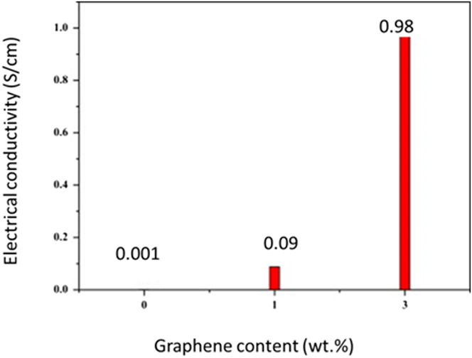
FIG. 12. Electrical conductivity of ZrO2 and ZrO2 reinforced graphene composites sintered by HFIHS. Reproduced from Ref. Reference Kwon, Lee and Shon87 with permission from Elsevier.
TABLE IV. Electrical properties of graphene (G) based ceramic composites.
a When loading was reported in volume percent, the density of bulk graphite (2.2 g/cm3) was used to convert to a weight percent loading.
VIII. CONCLUSION AND PERSPECTIVES
In conclusion, progress has been made in ceramic reinforcement using graphene over the last decade. The excellent mechanical and electrical properties of graphene render a huge potential for structural and functional applications of graphene–ceramic composites such as surface renewable electrodes, Reference Mohammad-Rezaei, Razmi and Jabbari122 low temperature fuel cells, Reference Wu, Lv, Peng, He and Mu46 energy storage materials, Reference Zhou, Lin, Huang, Zhong, Wang, Tang, Bi, Wan and Lin123 hip-joint prosthetics, Reference Gutierrez-Gonzalez, Smirnov, Centeno, Fernández, Alonso, Rocha, Torrecillas, Zurutuza and Bartolome124 and electronic devices. Reference Eda and Chhowalla125 In this review, an overview of the research in graphene–ceramic composites is provided with emphases on techniques to disperse graphene, processing of graphene–ceramic composite as well as the effects of graphene loading on properties of the composite. These three factors amongst other processing parameters are of the utmost importance; since they govern the resulting properties of graphene–ceramic composite. To achieve uniform dispersion, various mechanical methods such as ultrasonication, ball milling, and stirring was used. Selection of one or combination of these methods should be based on the desired end properties; since incorrect selection of the method may result in mechanical damage to graphene.
On another note, with the well-established knowledge on graphene behavior and their reinforcement mechanism in ceramics, there are still many challenges that should be further addressed to fully utilize the potential of these composite. They include but not limited to the following;
-
(1) From Table II, only a limited number of ceramics were used as structural materials for graphene reinforcement. It would be interesting to have more ceramic materials available in the market investigated to harness the application perspective of graphene based ceramic composites.
-
(2) Graphene dispersion techniques such as sonication or thermal shock techniques may reduce the aspect ratio of graphene platelets. This adversely affects the reinforcement of graphene based ceramic composites. As such, newer techniques of producing graphene platelets which preserves its conjugated structure should be explored.
-
(3) Most of the prepared graphene–ceramic composites are based on predispersion techniques where graphene dispersed in a solvent, followed by mixing with a ceramic material. Successes in purification and dispersion of graphene is satisfactory, however further research and standardization for graphene dispersion are crucial in addressing issues of quality and reliability. For example, specific tools which examine dispersion of graphene in the solvent can be developed.
-
(4) Different testing methods have been established to evaluate the fracture toughness of GCMC such as Vickers indentation, singe edge notched beam (SENB) and Chevron notch method. The differences among these methods such as size and shape of test specimen and loading configuration may lead to discrepancies of toughness values reported in literature. Thus, common (standard) method for determining fracture toughness of GCMC should be developed.
-
(5) Reinforcing ceramics with graphene may undoubtedly enhance properties of the composite. Nevertheless, issues associated with dispersing high graphene loading and deterioration of mechanical properties have been least investigated. To further address this issue, fundamental idea of stress transfer (interfacial bond strength) between ceramic and graphene are needed. For example; modeling, prediction and measuring interfacial adhesion of graphene–ceramic composites.
Despite the challenges and gaps in research, graphene based ceramic composites have established their commercial impact and expecting a brighter future in many applications. Significant efforts have been undertaken for scaling up graphene production. If the overriding problems with graphene can be addressed accordingly and research continues apace, it is very likely to expedite application perspective of graphene–ceramic composites to market place.
ACKNOWLEDGMENT
The authors would like to acknowledge the financial support from the Ministry of Science, Technology and Innovation of Malaysia for the research grant (E-Science code: 04-02-12-SF0198).
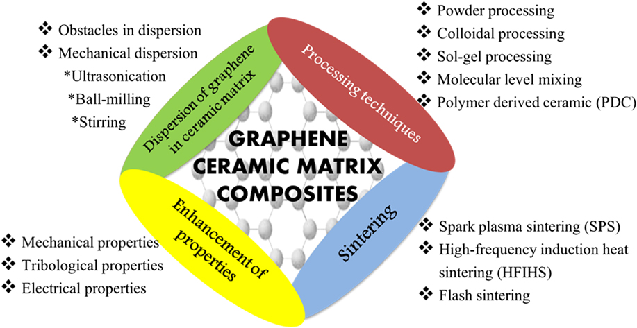

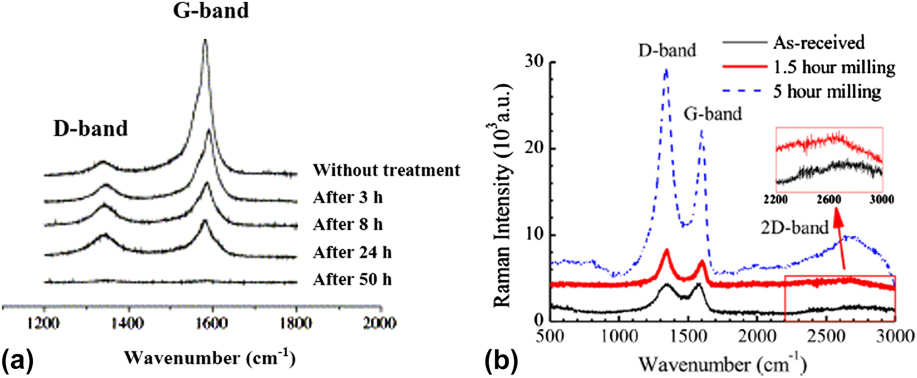


 Open access