


1 Introduction
Lasers with wavelengths ranging from 1100 to 1300 nm are promising for applications such as remote sensing[Reference Taylor, Feng and Calia1], spectral beam combining[Reference Feng, Zhang and Jiang2], and Tm-[Reference Qin, Huang, Feng, Shirakawa and Ueda3, Reference Du, Zhang, Xiao, Ma, Wang, Zhou and Liu4] and Ho[Reference Du, Zhang, Xiao, Ma, Wang, Zhou and Liu4–Reference Jackson7]-doped fiber laser pumping. In general, ytterbium-doped fiber lasers (YDFLs) are considered the most promising candidates for achieving high output powers based on the master oscillator power amplifier (MOPA) configuration[Reference Beier, Hupel, Kuhn, Hein, Nold, Proske, Sattler, Liem, Jauregui, Limpert, Haarlammert, Schreiber, Eberhardt and Tünnermann8]. However, traditional YDFLs can only efficiently operate within the band of 1000–1100 nm. The small emission cross-section of ytterbium and the amplified spontaneous emission (ASE) may deter YDFLs from realizing high output powers when the lasing wavelength exceeds 1100 nm[Reference Zhang, Xiao, Zhou, Zhang, Wang and Xu9]. Nevertheless, it has become a trend to realize lasers of a wide range of wavelengths by taking advantage of the stimulated Raman scattering (SRS) effect with appropriate and available pump sources. As the fiber power coupler replaces the wavelength division multiplexer (WDM), the Raman fiber laser has made significant progress in recent years.
In 2014, Zhang et al. proposed a 732-W integrated Yb-Raman fiber amplifier with dual-wavelength seeds of 1080 and 1120 nm. The length of the 20/400 $\unicode[STIX]{x03BC}\text{m}$
Yb-doped fiber (YDF) in their amplifier was 45 m[Reference Zhang, Xiao, Zhou, Wang and Xu10]. Subsequently, in 2015, a 1.5 kW Raman fiber laser was realized by using the same experimental configuration[Reference Zhang, Tao, Zhou, Wang and Xu11]. In 2014, Zhang et al. injected a seed laser at 1120 nm into a 1080 nm Yb-doped fiber MOPA consisting of a 12 m YDF and 70 m germanium-doped fiber (GDF) with the same parameter of 20/400
$\unicode[STIX]{x03BC}\text{m}$
Yb-doped fiber (YDF) in their amplifier was 45 m[Reference Zhang, Xiao, Zhou, Wang and Xu10]. Subsequently, in 2015, a 1.5 kW Raman fiber laser was realized by using the same experimental configuration[Reference Zhang, Tao, Zhou, Wang and Xu11]. In 2014, Zhang et al. injected a seed laser at 1120 nm into a 1080 nm Yb-doped fiber MOPA consisting of a 12 m YDF and 70 m germanium-doped fiber (GDF) with the same parameter of 20/400 $\unicode[STIX]{x03BC}\text{m}$
. As a result, a 1.28 kW 1120 nm Raman laser was realized[Reference Zhang, Liu, Jiang, Qi, He, Zhou, Gu and Feng12]. In 2015, Ma et al. designed linearly polarized output Yb-Raman cascaded oscillators consisting of a 1120 nm Raman Stokes cavity and 1080 nm laser cavity. They obtained a 1181 W, 1120 nm laser with an optical-to-optical efficiency of 74.3% using a 21-m-long 20/400-
$\unicode[STIX]{x03BC}\text{m}$
. As a result, a 1.28 kW 1120 nm Raman laser was realized[Reference Zhang, Liu, Jiang, Qi, He, Zhou, Gu and Feng12]. In 2015, Ma et al. designed linearly polarized output Yb-Raman cascaded oscillators consisting of a 1120 nm Raman Stokes cavity and 1080 nm laser cavity. They obtained a 1181 W, 1120 nm laser with an optical-to-optical efficiency of 74.3% using a 21-m-long 20/400- $\unicode[STIX]{x03BC}\text{m}$
YDF[Reference Ma, Zhang, Huang, Wang, Zhou and Liu13]. It should be noted that all the approaches mentioned above adopt the forward-pumped configuration, in which the output laser is in the same direction as the pump laser. Both theoretical[Reference Ying, Cao, Yu, Wang, Wang and Chen14] and experimental results[Reference Xiao, Yan, Li, Sun, Wang, Huang and Gong15] prove that the backward pumping Raman threshold should be larger than that of the forward pumping. However, the relatively small gap between the first- and second-order Raman threshold limits the power scaling of the first-order Raman wave. Thus, backward pumping or bidirectional pumping is an effective and competitive method to address the problem, which presents yet another challenge for the backward fiber coupler.
$\unicode[STIX]{x03BC}\text{m}$
YDF[Reference Ma, Zhang, Huang, Wang, Zhou and Liu13]. It should be noted that all the approaches mentioned above adopt the forward-pumped configuration, in which the output laser is in the same direction as the pump laser. Both theoretical[Reference Ying, Cao, Yu, Wang, Wang and Chen14] and experimental results[Reference Xiao, Yan, Li, Sun, Wang, Huang and Gong15] prove that the backward pumping Raman threshold should be larger than that of the forward pumping. However, the relatively small gap between the first- and second-order Raman threshold limits the power scaling of the first-order Raman wave. Thus, backward pumping or bidirectional pumping is an effective and competitive method to address the problem, which presents yet another challenge for the backward fiber coupler.
In 2016, our group realized a bidirectional pumped Raman fiber laser, which consisted of a single-wavelength seed and a one-stage bidirectional pumped amplifier. A 30-m-long 20/400 $\unicode[STIX]{x03BC}\text{m}$
YDF was adopted in the amplifier. Under a pump power of 5487 W, a 3889 W output power of the first-order Raman amplification was achieved with an optical-to-optical efficiency of 70.9%[Reference Xiao, Yan, Li, Sun, Wang, Huang and Gong15].
$\unicode[STIX]{x03BC}\text{m}$
YDF was adopted in the amplifier. Under a pump power of 5487 W, a 3889 W output power of the first-order Raman amplification was achieved with an optical-to-optical efficiency of 70.9%[Reference Xiao, Yan, Li, Sun, Wang, Huang and Gong15].
In the aforementioned examples, the adopted YDF had a relatively small core size of $20~\unicode[STIX]{x03BC}\text{m}$
. This is because smaller core sizes, as well as longer-gain fibers, can induce higher Raman gains. However, the accompanying self-phase modulation and four-wave multiplexing also induce spectral broadening because of the high laser density in the small-core-size fiber. In some cases, high-power and narrow bandwidth lasers are required. For example, the spectrum beam combining is an effective method to break through the limitation of output power in single mode fiber. And the basic elements of spectrum beam combining are high-power and narrow bandwidth lasers with different operating wavelengths[Reference Feng, Zhang and Jiang2]. The spectral broadening could be suppressed by using a larger-core-size fiber. In 2018, Glick et al. reported a 1.2 kW cladding pumped Raman laser by using a 80-m-long specialty multi-layer fiber (25/45/250
$20~\unicode[STIX]{x03BC}\text{m}$
. This is because smaller core sizes, as well as longer-gain fibers, can induce higher Raman gains. However, the accompanying self-phase modulation and four-wave multiplexing also induce spectral broadening because of the high laser density in the small-core-size fiber. In some cases, high-power and narrow bandwidth lasers are required. For example, the spectrum beam combining is an effective method to break through the limitation of output power in single mode fiber. And the basic elements of spectrum beam combining are high-power and narrow bandwidth lasers with different operating wavelengths[Reference Feng, Zhang and Jiang2]. The spectral broadening could be suppressed by using a larger-core-size fiber. In 2018, Glick et al. reported a 1.2 kW cladding pumped Raman laser by using a 80-m-long specialty multi-layer fiber (25/45/250 $\unicode[STIX]{x03BC}\text{m}$
)[Reference Glick, Shamir, Aviel, Sintov, Goldring, Shafir and Pearl16]. Chen et al. proposed a 987 W Raman laser with a large GRIN fiber[Reference Chen, Leng, Xiao, Yao and Zhou17].
$\unicode[STIX]{x03BC}\text{m}$
)[Reference Glick, Shamir, Aviel, Sintov, Goldring, Shafir and Pearl16]. Chen et al. proposed a 987 W Raman laser with a large GRIN fiber[Reference Chen, Leng, Xiao, Yao and Zhou17].
In theory, Ying et al. analyzed the Raman noise-enhanced SRS in a continuous-wave fiber amplifier with a single-frequency model[Reference Ying, Cao, Yu, Wang, Wang and Chen14]. Zhang et al. [Reference Zhang, Xiao, Zhou, Wang and Xu10], Xiao et al. [Reference Xiao, Yan, Li, Sun, Wang, Huang and Gong15], Chen et al. [Reference Chen, Xiao, Xu, Leng and Zhou18] and Rini et al. [Reference Rini, Cristiani and Degiorgio19] adopted the single-frequency model to calculate the output power of their Raman oscillator or amplifier. However, in the single-frequency model, Raman gain coefficient is simplified to a number irrespective of wavelength. Actually, conventional silica fibers have a wide Raman gain spectrum. Therefore, it is not accurate for power calculation via this model. Besides, the spectrum evolution along the fiber cannot be calculated either.
In this paper, we presented both the experimental realization and theoretical analysis of a 3.7 kW, 1123 nm Raman fiber laser system based on the dual-wavelength bidirectional pumping configuration. A total forward pump power of 4200 W and a backward pump power of 2510 W were injected into the amplifier of the system. The forward pumping used long-wavelength fiber laser sources at 1018 nm for reducing the thermal effect caused by quantum defects. Due to the slow absorption of the 1018 nm fiber laser, 976 nm laser diodes (LDs) were used as the backward pump sources to reduce the unabsorbed pump light and provide an enhanced absorption. In the core of YDF, the 1070 nm signal laser was amplified via Yb gain and then it was converted to 1123 nm laser via Raman gain. The system incorporated a 60-m-long 25/400 $\unicode[STIX]{x03BC}\text{m}$
YDF, realizing a 3 dB spectral width of 6.8 nm. Further, the backward Raman laser had a power of 65 W with a 3 dB spectral width of 5.2 nm. Moreover, we developed a multi-frequency model of the Raman fiber laser taking into consideration the Raman gain spectrum and ASE. Using this model, we can simulate the spectrum and power evolution along the fiber. The numerical simulation results were in good agreement with the experimental results. Then we analyzed the new peak at 1095 nm and we found that it was generated from ASE initially and was strongly amplified along the fiber because of much larger gain coefficient. The new peak only appeared when the gain fiber length was larger than 50 m. In addition, we spliced another GDF after the gain fiber to acquire a high Raman gain for realizing a second-order Raman laser. When the length of the GDF reached 70 m, a 1.5 kW, 1187 nm second-order Raman laser was obtained.
$\unicode[STIX]{x03BC}\text{m}$
YDF, realizing a 3 dB spectral width of 6.8 nm. Further, the backward Raman laser had a power of 65 W with a 3 dB spectral width of 5.2 nm. Moreover, we developed a multi-frequency model of the Raman fiber laser taking into consideration the Raman gain spectrum and ASE. Using this model, we can simulate the spectrum and power evolution along the fiber. The numerical simulation results were in good agreement with the experimental results. Then we analyzed the new peak at 1095 nm and we found that it was generated from ASE initially and was strongly amplified along the fiber because of much larger gain coefficient. The new peak only appeared when the gain fiber length was larger than 50 m. In addition, we spliced another GDF after the gain fiber to acquire a high Raman gain for realizing a second-order Raman laser. When the length of the GDF reached 70 m, a 1.5 kW, 1187 nm second-order Raman laser was obtained.
2 Experimental setup

Figure 1. Experimental setup of the Raman laser. PM: power meter, OSA: optical spectrum analyzer, CLS: cladding light stripper, YDFL:Yb-doped fiber laser.

Figure 2. Forward and backward output power as a function of pump power (only forward pumping in part I and both forward and backward pumping in part II).
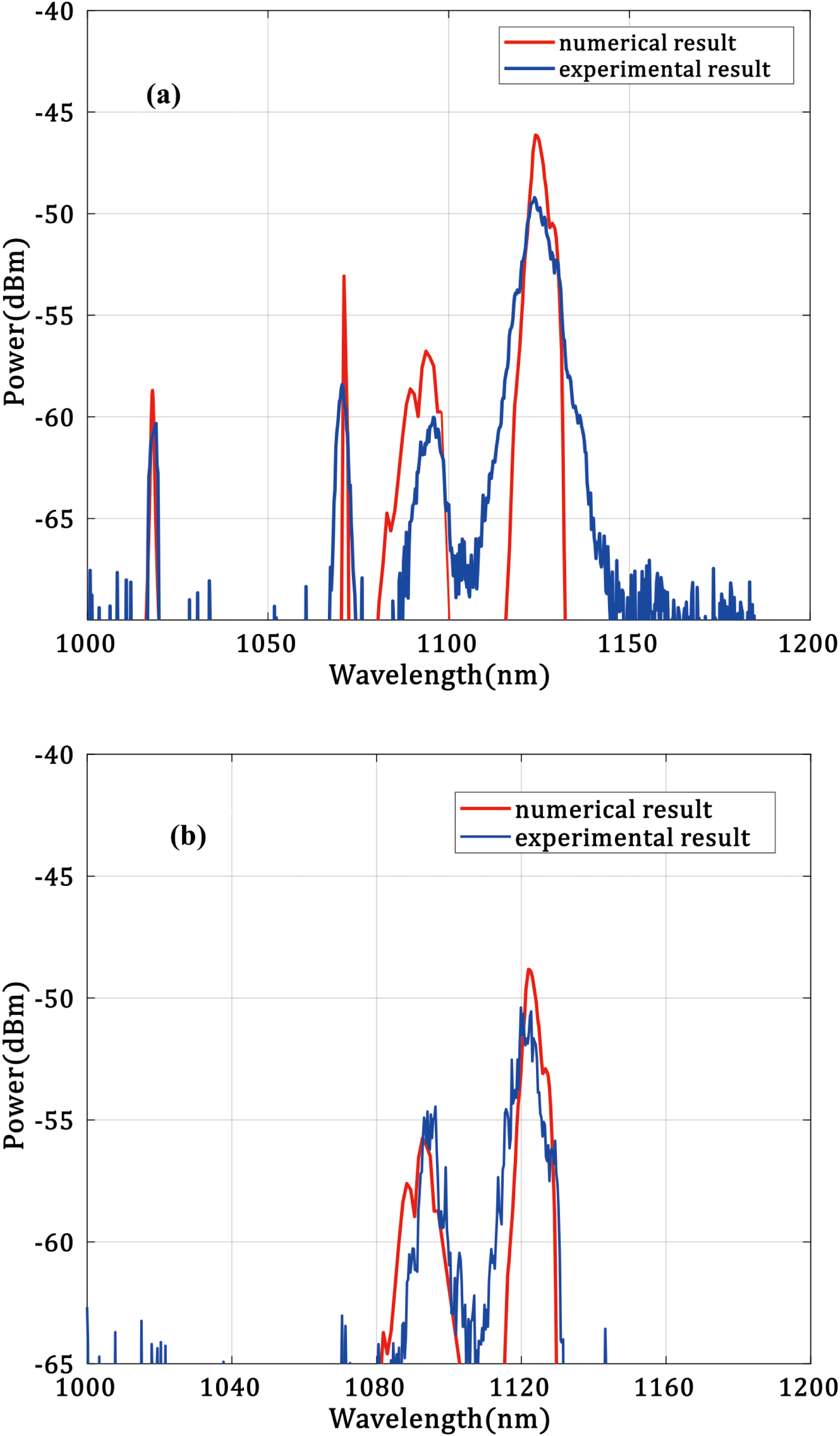
Figure 3. (a) Forward spectrum and (b) backward spectrum. The red and blue lines represent the numerical simulation and experimental results, respectively.
The Raman fiber laser employing the MOPA configuration consists of a 1070 nm laser seed and an amplifier of the dual-wavelength bidirectional pumping configuration, as shown in Figure 1. The seed comprising a pair of fiber Bragg gratings (FBGs) is pumped by an LD through a $(2+1)\times 1$
coupler. The maximum output power of the seed is 107.4 W and the 3 dB linewidth is 0.9 nm. In the amplifier, a 60-m-long Yb-doped double-cladding fiber (25/400
$(2+1)\times 1$
coupler. The maximum output power of the seed is 107.4 W and the 3 dB linewidth is 0.9 nm. In the amplifier, a 60-m-long Yb-doped double-cladding fiber (25/400 $\unicode[STIX]{x03BC}\text{m}$
) is adopted as the gain medium. To reduce the thermal effect caused by quantum defects, 1018 nm YDFLs[Reference Yan, Wang, Li, Huang, Sun, Xiao and Gong20, Reference Yan, Wang, Wang, Huang, Li, Xiao and Gong21] are used as the forward pump source. The cladding absorption coefficient of YDF at 976 nm is 1.8 dB/m. In the experiment, the pump powers of six 1018 nm YDFLs are coupled into the gain fiber with a
$\unicode[STIX]{x03BC}\text{m}$
) is adopted as the gain medium. To reduce the thermal effect caused by quantum defects, 1018 nm YDFLs[Reference Yan, Wang, Li, Huang, Sun, Xiao and Gong20, Reference Yan, Wang, Wang, Huang, Li, Xiao and Gong21] are used as the forward pump source. The cladding absorption coefficient of YDF at 976 nm is 1.8 dB/m. In the experiment, the pump powers of six 1018 nm YDFLs are coupled into the gain fiber with a $(6+1)\times 1$
coupler. The pump coupler efficiency can reach 99% with a total forward pump power of 4296 W. To provide an enhanced absorption and reduce the unabsorbed pump light, six 976 nm LDs provide backward pump power through another
$(6+1)\times 1$
coupler. The pump coupler efficiency can reach 99% with a total forward pump power of 4296 W. To provide an enhanced absorption and reduce the unabsorbed pump light, six 976 nm LDs provide backward pump power through another $(6+1)\times 1$
coupler. The pump power of each LD is approximately 400 W and the total backward pump power is 2510 W. All the couplers mentioned above are homemade with an excellent coupling efficiency and very small loss coefficient[Reference Xiao, Yan, Ren, Chen and Gong22, Reference Xiao, Ren, Yan, Chen and Gong23]. A cladding light stripper (CLS) is spliced with the backward coupler to leak the residual pump laser. At the end of the experimental system, a specially made end cap, whose coating is designed to anti-reflect the Raman laser, is spliced after the CLS and cooled by water. In addition to the power meter, optical spectrum analyzers are used both before the signal input port of the seed coupler and after the end cap to monitor the real-time forward and backward output spectra, respectively.
$(6+1)\times 1$
coupler. The pump power of each LD is approximately 400 W and the total backward pump power is 2510 W. All the couplers mentioned above are homemade with an excellent coupling efficiency and very small loss coefficient[Reference Xiao, Yan, Ren, Chen and Gong22, Reference Xiao, Ren, Yan, Chen and Gong23]. A cladding light stripper (CLS) is spliced with the backward coupler to leak the residual pump laser. At the end of the experimental system, a specially made end cap, whose coating is designed to anti-reflect the Raman laser, is spliced after the CLS and cooled by water. In addition to the power meter, optical spectrum analyzers are used both before the signal input port of the seed coupler and after the end cap to monitor the real-time forward and backward output spectra, respectively.
3 Experimental results
Figure 2 shows the output power in the amplifier varying with the input pump power. In part I of Figure 2, the forward pump power increases to a maximum of 4200 W while the backward pump power remains disabled. Then, in part II, the backward pump power increases from zero to a maximum of 2510 W while the forward pump power reaches 4200 W. The figure clearly indicates that the total output power (‘ $\blacktriangle$
’ in Figure 2) increases almost linearly with the input pump power, and the maximum output power is 4290 W. The output spectrum is depicted as a blue line in Figure 3(a), and no second-order Raman laser is found. Because of the small absorption cross-section at 1018 nm, the slow absorption of the forward pump laser along the fiber length causes some residual pump power. Therefore, we spliced a homemade CLS after the gain fiber. The CLS can leak almost all high numerical aperture (NA) cladding light, but not function well for low NA cladding light. In the experiment, the forward pump source is 1018 nm fiber laser of high brightness and low NA. Hence, after the CLS, there is still 200 W residual low NA cladding pump power. It is interesting to note that in addition to the 1070 nm signal laser, a new peak appears at a wavelength of about 1095 nm, which will be discussed in detail later. The power of the Raman laser (‘
$\blacktriangle$
’ in Figure 2) increases almost linearly with the input pump power, and the maximum output power is 4290 W. The output spectrum is depicted as a blue line in Figure 3(a), and no second-order Raman laser is found. Because of the small absorption cross-section at 1018 nm, the slow absorption of the forward pump laser along the fiber length causes some residual pump power. Therefore, we spliced a homemade CLS after the gain fiber. The CLS can leak almost all high numerical aperture (NA) cladding light, but not function well for low NA cladding light. In the experiment, the forward pump source is 1018 nm fiber laser of high brightness and low NA. Hence, after the CLS, there is still 200 W residual low NA cladding pump power. It is interesting to note that in addition to the 1070 nm signal laser, a new peak appears at a wavelength of about 1095 nm, which will be discussed in detail later. The power of the Raman laser (‘ $\blacksquare$
’ in Figure 2) is approximately 3700 W, which was calculated by spectral integration. The forward first-order Raman threshold is about 3000 W. The center wavelength of the Raman laser is 1123.8 nm and the 3 dB width is 6.8 nm, which is much narrower than that in Ref. [Reference Xiao, Yan, Li, Sun, Wang, Huang and Gong15]. We ascribed the narrow output linewidth to the adoption of the 25/400
$\blacksquare$
’ in Figure 2) is approximately 3700 W, which was calculated by spectral integration. The forward first-order Raman threshold is about 3000 W. The center wavelength of the Raman laser is 1123.8 nm and the 3 dB width is 6.8 nm, which is much narrower than that in Ref. [Reference Xiao, Yan, Li, Sun, Wang, Huang and Gong15]. We ascribed the narrow output linewidth to the adoption of the 25/400 $\unicode[STIX]{x03BC}\text{m}$
instead of 20/400
$\unicode[STIX]{x03BC}\text{m}$
instead of 20/400 $\unicode[STIX]{x03BC}\text{m}$
gain fiber, thus leading to a lower power density in the fiber core. We also monitored the backward output power, indicated by the green line (‘
$\unicode[STIX]{x03BC}\text{m}$
gain fiber, thus leading to a lower power density in the fiber core. We also monitored the backward output power, indicated by the green line (‘ $\bullet$
’) in Figure 2, and its spectrum is presented in Figure 3(b). Only a Raman laser and new peak near the 1095 nm laser can be found in the backward spectrum. The center wavelength and 3 dB spectral width of the backward Raman laser are 1121.9 and 5.2 nm, respectively.
$\bullet$
’) in Figure 2, and its spectrum is presented in Figure 3(b). Only a Raman laser and new peak near the 1095 nm laser can be found in the backward spectrum. The center wavelength and 3 dB spectral width of the backward Raman laser are 1121.9 and 5.2 nm, respectively.
In Figure 2, the curve of the backward power versus pump power can be divided into three sections. The first one is when the forward pump power is below 3000 W, in which the Raman threshold has not been reached and only Raman noise less than 3 W can be detected. In the second section, the forward pump power rises above the Raman threshold, causing the backward Raman laser power to rapidly amplify to about 65 W. The backward power is much lower than the forward power because the 1070 nm laser barely propagates in the backward direction. In the third part, when the forward pump power stops rising while the backward pump power starts rising, the power of the backward Raman laser grows slowly. Through the backward power curve and forward Raman power curve, we can easily confirm that the first-order Raman threshold is about 3000 W in the experiment.

Figure 4. $M^{2}$
factor of output laser.
$M^{2}$
factor of output laser.
The $M^{2}$
factor of the output laser was measured by a PRIMES High-Power-LaserQualityMonitor. The
$M^{2}$
factor of the output laser was measured by a PRIMES High-Power-LaserQualityMonitor. The $M^{2}$
factor of 1070 nm seed is 1.39. When the pump power was 3020 W, the
$M^{2}$
factor of 1070 nm seed is 1.39. When the pump power was 3020 W, the $M^{2}$
factor deteriorated to 2.18, as shown in Figure 4. We think that it is a result of thermal effect and the mismatch of the core diameter in the oscillator and amplifier.
$M^{2}$
factor deteriorated to 2.18, as shown in Figure 4. We think that it is a result of thermal effect and the mismatch of the core diameter in the oscillator and amplifier.
4 Numerical simulation
We want to figure out the spectral evolution in the fiber amplifier and the existing single-frequency model does not work anymore. Thus, we build the multi-frequency model based on steady-state rate equations to solve the problem. The spectral broadening caused by the Raman gain, ASE, seed and pump light linewidth in the evolutions can be calculated via the multi-frequency model. The model includes the following equations:
 $$\begin{eqnarray}\displaystyle \frac{\unicode[STIX]{x2202}P_{p}^{\pm }(z,\unicode[STIX]{x1D706}_{p}^{\pm })}{\unicode[STIX]{x2202}z} & = & \displaystyle \unicode[STIX]{x1D6E4}_{p}\{[\unicode[STIX]{x1D70E}_{a,p}(\unicode[STIX]{x1D706}_{p})+\unicode[STIX]{x1D70E}_{e,p}(\unicode[STIX]{x1D706}_{p})]N_{2}(z)\nonumber\\ \displaystyle & & \displaystyle -\,\unicode[STIX]{x1D70E}_{a,p}(\unicode[STIX]{x1D706}_{p})N\!\}P_{p}^{\pm }(z,\unicode[STIX]{x1D706}_{p})-\unicode[STIX]{x1D6FC}_{p}P_{p}^{\pm }(z,\unicode[STIX]{x1D706}_{p}),\nonumber\\ \displaystyle & & \displaystyle\end{eqnarray}$$
 $$\begin{eqnarray}\displaystyle \frac{\unicode[STIX]{x2202}P_{s}(z,\unicode[STIX]{x1D706}_{s})}{\unicode[STIX]{x2202}z} & = & \displaystyle \unicode[STIX]{x1D6E4}_{s}\{[\unicode[STIX]{x1D70E}_{a,s}(\unicode[STIX]{x1D706}_{s})+\unicode[STIX]{x1D70E}_{e,s}(\unicode[STIX]{x1D706}_{s})]N_{2}(z)\nonumber\\ \displaystyle & & \displaystyle -\,\unicode[STIX]{x1D70E}_{a,s}(\unicode[STIX]{x1D706}_{s})N\!\}P_{s}(z,\unicode[STIX]{x1D706}_{s})-\unicode[STIX]{x1D6FC}_{s}P_{s}(z,\unicode[STIX]{x1D706}_{s}),\nonumber\\ \displaystyle & & \displaystyle -\int _{r1}\frac{\unicode[STIX]{x1D706}}{\unicode[STIX]{x1D706}_{s}}\frac{g_{r}(\unicode[STIX]{x1D706}-\unicode[STIX]{x1D706}_{s})}{A_{\text{eff}}}[P_{r1}^{+}(z,\unicode[STIX]{x1D706})+P_{r}^{-}(z,\unicode[STIX]{x1D706})\nonumber\\ \displaystyle & & \displaystyle +\,4P_{\text{spon1}}]P_{s}(z,\unicode[STIX]{x1D706}_{s})\,\text{d}\unicode[STIX]{x1D706},\end{eqnarray}$$
 $$\begin{eqnarray}\displaystyle \frac{\unicode[STIX]{x2202}P_{r1}^{\pm }(z,\unicode[STIX]{x1D706}_{r1})}{\unicode[STIX]{x2202}z} & = & \displaystyle \pm \unicode[STIX]{x1D6E4}_{r1}\{[\unicode[STIX]{x1D70E}_{a,r1}(\unicode[STIX]{x1D706}_{r1})+\unicode[STIX]{x1D70E}_{e,r1}(\unicode[STIX]{x1D706}_{r1})]N_{2}(z)\nonumber\\ \displaystyle & & \displaystyle -\,\unicode[STIX]{x1D70E}_{a,r1}(\unicode[STIX]{x1D706}_{r1})N\!\}P_{r1}^{\pm }(z,\unicode[STIX]{x1D706}_{r1})\nonumber\\ \displaystyle & & \displaystyle \mp \,\unicode[STIX]{x1D6FC}_{r1}P_{r1}^{\pm }(z,\unicode[STIX]{x1D706}_{r1})\pm \int _{s}\frac{g_{r}(\unicode[STIX]{x1D706}_{r1}-\unicode[STIX]{x1D706}_{s})}{A_{\text{eff}}}\nonumber\\ \displaystyle & & \displaystyle \times \,[P_{r1}^{\pm }(z,\unicode[STIX]{x1D706}_{r1})+2P_{\text{spon}}]P_{s}(z,\unicode[STIX]{x1D706})\,\text{d}\unicode[STIX]{x1D706}\nonumber\\ \displaystyle & & \displaystyle \mp \int _{r2}\frac{\unicode[STIX]{x1D706}}{\unicode[STIX]{x1D706}_{r1}}\frac{g_{r}(\unicode[STIX]{x1D706}-\unicode[STIX]{x1D706}_{r1})}{A_{\text{eff}}}[P_{r2}^{+}(z,\unicode[STIX]{x1D706})\nonumber\\ \displaystyle & & \displaystyle +\,P_{r}^{-}(z,\unicode[STIX]{x1D706})+4P_{\text{spon1}}]P_{r1}^{\pm }(z,\unicode[STIX]{x1D706}_{r1})\,\text{d}\unicode[STIX]{x1D706},\qquad\end{eqnarray}$$
 $$\begin{eqnarray}\displaystyle \frac{\unicode[STIX]{x2202}P_{r2}^{\pm }(z,\unicode[STIX]{x1D706}_{r2})}{\unicode[STIX]{x2202}z} & = & \displaystyle \pm \unicode[STIX]{x1D6E4}_{r2}\{[\unicode[STIX]{x1D70E}_{a,r2}(\unicode[STIX]{x1D706}_{r2})+\unicode[STIX]{x1D70E}_{e,r2}(\unicode[STIX]{x1D706}_{r2})]N_{2}(z)\nonumber\\ \displaystyle & & \displaystyle -\,\unicode[STIX]{x1D70E}_{a,r2}(\unicode[STIX]{x1D706}_{r2})N\!\}\!P_{r2}^{\pm }(z,\unicode[STIX]{x1D706}_{r2})\mp \unicode[STIX]{x1D6FC}_{r2}P_{r2}^{\pm }(z,\unicode[STIX]{x1D706}_{r2})\!\nonumber\\ \displaystyle & & \displaystyle \pm \int _{r1}\frac{g_{r}(\unicode[STIX]{x1D706}_{r2}-\unicode[STIX]{x1D706}_{s})}{A_{\text{eff}}}[P_{r2}^{\pm }(z,\unicode[STIX]{x1D706}_{r2})+2P_{\text{spon}}]\nonumber\\ \displaystyle & & \displaystyle \times \,[P_{r1}^{+}(z,\unicode[STIX]{x1D706})+P_{r1}^{-}(z,\unicode[STIX]{x1D706})]\,\text{d}\unicode[STIX]{x1D706},\end{eqnarray}$$
 $$\begin{eqnarray}\displaystyle \frac{\unicode[STIX]{x2202}P_{\text{ase}}^{\pm }(z,\unicode[STIX]{x1D706})}{\unicode[STIX]{x2202}z\unicode[STIX]{x2202}\unicode[STIX]{x1D706}} & = & \displaystyle \pm \unicode[STIX]{x1D6E4}_{\text{ase}}\unicode[STIX]{x1D70E}_{e,s}(\unicode[STIX]{x1D706}_{s})N_{2}(z)\frac{hc^{2}}{\unicode[STIX]{x1D706}^{3}}\mp \unicode[STIX]{x1D6FC}_{\text{ase}}P_{\text{ase}}^{\pm }(z,\unicode[STIX]{x1D706}),\nonumber\\ \displaystyle & & \displaystyle\end{eqnarray}$$
 $$\begin{eqnarray}\displaystyle \frac{N_{2}(z)}{N} & = & \displaystyle \frac{\displaystyle \mathop{\sum }_{i=p^{\pm },p^{-},s,r_{1}^{\pm },r_{2}^{\pm },\text{ase}^{\pm }}\int _{i}P_{i}(z,\unicode[STIX]{x1D706})\unicode[STIX]{x1D70E}_{a,i}\unicode[STIX]{x1D6E4}_{i}\,\text{d}\unicode[STIX]{x1D706}}{\displaystyle \mathop{\sum }_{i=p^{\pm },p^{-},s,r_{1}^{\pm },r_{2}^{\pm },\text{ase}^{\pm }}\int _{i}P_{i}(z,\unicode[STIX]{x1D706})(\unicode[STIX]{x1D70E}_{a,i}+\unicode[STIX]{x1D70E}_{e,i})\unicode[STIX]{x1D6E4}_{i}\,\text{d}\unicode[STIX]{x1D706}+\frac{hcA_{c}}{\unicode[STIX]{x1D70F}}}.\nonumber\\ \displaystyle & & \displaystyle\end{eqnarray}$$
In the above equations, the subscripts $p$
,
$p$
, $s$
,
$s$
, $r1$
and
$r1$
and $r2$
represent the pump laser, signal laser, first-order Raman wave and second-order Raman wave, respectively. The superscripts ‘
$r2$
represent the pump laser, signal laser, first-order Raman wave and second-order Raman wave, respectively. The superscripts ‘ $+$
’ and ‘
$+$
’ and ‘ $-$
’ represent the forward-propagating waves and backward-propagating waves.
$-$
’ represent the forward-propagating waves and backward-propagating waves. $\unicode[STIX]{x1D6E4}$
is the filling factor,
$\unicode[STIX]{x1D6E4}$
is the filling factor, $\unicode[STIX]{x1D6FC}$
is the background loss coefficient,
$\unicode[STIX]{x1D6FC}$
is the background loss coefficient, $A_{\text{eff}}$
is the effective mode field area of the core,
$A_{\text{eff}}$
is the effective mode field area of the core, $N$
is the population density of doped ions,
$N$
is the population density of doped ions, $N_{2}$
is the upper lasing level population density,
$N_{2}$
is the upper lasing level population density, $\unicode[STIX]{x1D70E}_{a}$
and
$\unicode[STIX]{x1D70E}_{a}$
and $\unicode[STIX]{x1D70E}_{e}$
are functions of the wavelength representing the absorption and emission cross-sections, respectively,
$\unicode[STIX]{x1D70E}_{e}$
are functions of the wavelength representing the absorption and emission cross-sections, respectively, $h$
is Planck’s constant,
$h$
is Planck’s constant, $c$
is the speed of light in vacuum and
$c$
is the speed of light in vacuum and $\unicode[STIX]{x1D70F}$
is the spontaneous lifetime of doped ions. The subscripts under the integral sign indicate that the integral domain is the wavelength of the corresponding wave. The adopted values of the parameters mentioned are listed in Table 1. The Raman gain is a function of the wavelength shift between the Raman wave and its corresponding Raman pump wave. Figure 5 depicts the Raman gain spectrum in a 25/400
$\unicode[STIX]{x1D70F}$
is the spontaneous lifetime of doped ions. The subscripts under the integral sign indicate that the integral domain is the wavelength of the corresponding wave. The adopted values of the parameters mentioned are listed in Table 1. The Raman gain is a function of the wavelength shift between the Raman wave and its corresponding Raman pump wave. Figure 5 depicts the Raman gain spectrum in a 25/400 $\unicode[STIX]{x03BC}\text{m}$
gain fiber with a Raman pump wavelength of about 1070 nm[Reference Feng24, Reference Chen, Shirakawa, Fan, Ueda, Olausson, Lyngsø and Broeng25].
$\unicode[STIX]{x03BC}\text{m}$
gain fiber with a Raman pump wavelength of about 1070 nm[Reference Feng24, Reference Chen, Shirakawa, Fan, Ueda, Olausson, Lyngsø and Broeng25].
Table 1. Parameters for the numerical calculations.


Figure 5. Raman gain spectrum in a $25/400~\unicode[STIX]{x03BC}\text{m}$
gain fiber.
$25/400~\unicode[STIX]{x03BC}\text{m}$
gain fiber.
5 Simulation results and discussion
5.1 The simulation of the 3.7 kW bidirectional Raman fiber laser
Figure 6 illustrates the power distribution along the fiber calculated from the multi-frequency model. The 1070 nm laser power decreased while the first-order Raman laser power rose rapidly from a fiber length of 45 to 60 m. At the end of the gain fiber, the Raman laser power was calculated to 3850 W and the backward Raman laser power was calculated to 69 W. The numerical results of the forward and backward spectra were represented by a red line in Figures 3(a) and 3(b), respectively, which agreed with the experiment well.

Figure 6. (a) Calculated power distributions of the (a) pump laser, signal laser and Raman laser along the fiber in the multi-frequency model ( $L=60$
m), and (b) backward Raman laser in the dotted box in (a).
$L=60$
m), and (b) backward Raman laser in the dotted box in (a).
We also used the model to simulate the spectrum evolution along the fiber, as shown in Figure 7. We can see that the Yb fiber Raman gain spectrum possessed two peaks where the shift frequencies were 13 and 14.7 THz, as shown in Figure 5 [Reference Stolen, Lee and Jain28–Reference Glick, Fromzel, Zhang, Dahan, Tergabrielyan, Pattnaik and Dubinskii30]. Therefore, in the spectrum shown in Figure 7, next to the main peak of the Raman laser at 1123 nm, there was another peak at 1129 nm. The simulated results of output spectrum for forward and backward direction were shown as red lines in Figures 3(a) and 3(b), respectively. As can be seen clearly, the shapes of the simulated and experimental output spectra were similar. The 3 dB spectral width was calculated to 5.3 nm, which was little narrower than that of the experimental result (6.8 nm). We attributed it to omitting other nonlinear effects under the high-intensity light field, which will be left for future research.
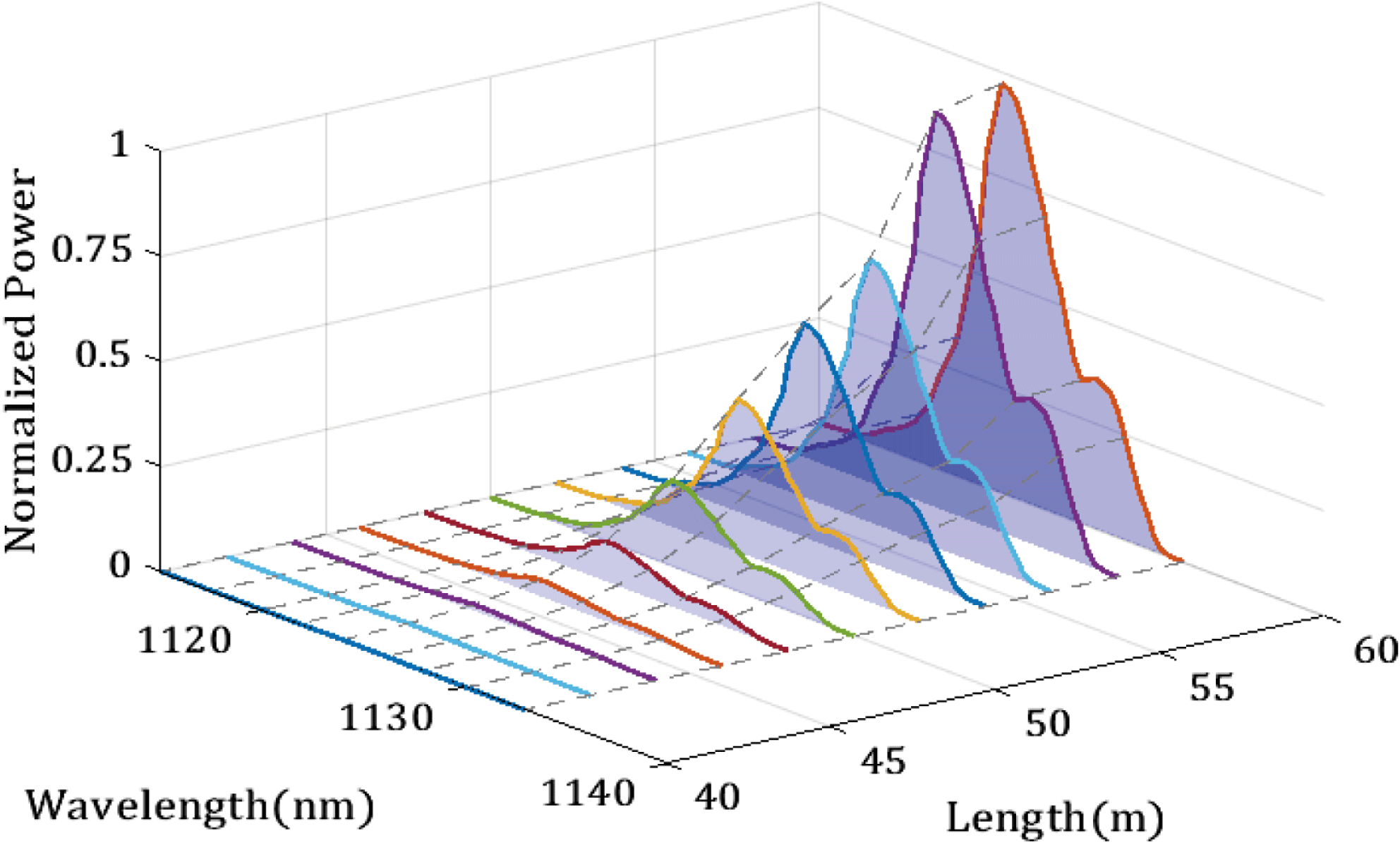
Figure 7. Transmission and amplification of Raman laser from 40 to 60 m (SRS has not been generated from 0 to 40 m).
5.2 The comparison of 976 nm and 1018 nm pump sources
In the experiment, we adopted dual-wavelength pump configuration, consisting of 1018 nm YDFLs and 976 nm LDs as the forward and backward pump sources, respectively. It should be noted that due to the small quantum defect and a flatter power distribution, the 1018 nm YDFLs pumping suffers from the less thermal effect than the 976 nm LDs pumping. Therefore, the temperature of gain fiber in 976 nm LDs pump configuration is higher [Reference Jauregui, Limpert and Tünnermann31–Reference Zhou, Xiao, Leng, Xu, Chen, Zhang and Liu33].
We analyzed the impact of different pump source on temperature distribution via simulation under the same pump power. The forward pump power and the backward pump power were set to 4200 W and 2510 W, respectively. The result was shown in Figure 8. Two situations were analyzed to compare the difference. One of the situation has the same parameters with our actual experiment, while in the other situation only 976 nm LDs were used as pumping source. The simulation result showed that the highest temperature in the gain fiber of these two configurations was $36^{\circ }$
and
$36^{\circ }$
and $210^{\circ }$
, respectively. In consideration of thermal effect, adopting 1018 nm YDFLs as pump source will have more potential for further power scaling.
$210^{\circ }$
, respectively. In consideration of thermal effect, adopting 1018 nm YDFLs as pump source will have more potential for further power scaling.

Figure 8. Temperature distribution at the input end of two situations. (a) The experiment; (b) only 976 nm LDs were used.
5.3 The analysis of the new peak at 1095 nm
As mentioned above, we found that a new peak at a wavelength of about 1095 nm appeared when the total output power exceeded 1360 W, much smaller than the Raman threshold. Thus, we assumed that it was not related to the SRS. In addition, the wavelength of the new peak shifted from 1089 to 1095 nm while the total output power rose from 1360 to 4290 W, as shown in Figure 9.
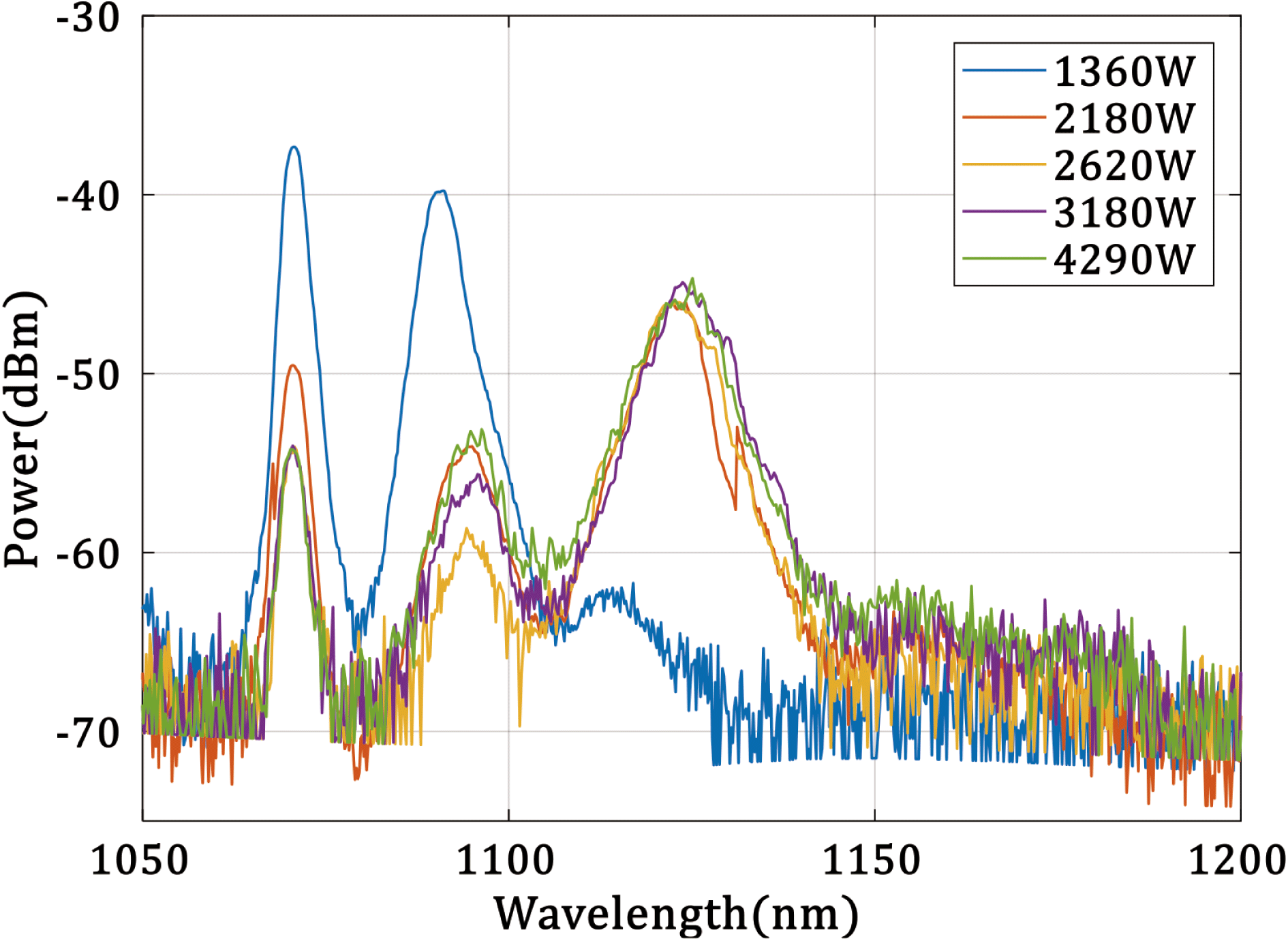
Figure 9. Output spectra under different powers (the length of YDF is 60 m).
Without the item of SRS, we integrated both sides of Equation (2) in the region $[0,L]$
, obtaining the following expression of the gain coefficient
$[0,L]$
, obtaining the following expression of the gain coefficient $G$
:
$G$
:
 $$\begin{eqnarray}\displaystyle G(\unicode[STIX]{x1D706})=\ln \frac{P_{s}(L)}{P_{s}(0)} & = & \displaystyle \unicode[STIX]{x1D6E4}_{s}[\unicode[STIX]{x1D70E}_{a,s}(\unicode[STIX]{x1D706})+\unicode[STIX]{x1D70E}_{e,s}(\unicode[STIX]{x1D706})]\int _{0}^{L}N_{2}(z)\,\text{d}z\nonumber\\ \displaystyle & & \displaystyle -\,[\unicode[STIX]{x1D70E}_{a,s}(\unicode[STIX]{x1D706})N+\unicode[STIX]{x1D6FC}_{s}]L.\end{eqnarray}$$
It is clear that the gain coefficient $G$
was the function of wavelength. Figure 10 illustrated the exponential of gain coefficient when forward pumping power was 1800 W. Owing to a very long length of gain fiber and high pump power, the maximum gain coefficient was located at 1095 nm. At the beginning of the amplifier, the 1070 nm signal laser was dominant. However, the 1095 nm laser, only generated from ASE initially, was strongly amplified along the fiber because of much larger gain coefficient. Figure 11 presented the numerical simulation results of the power evolution along the fiber according to Equations (1)–(6). The gain coefficient
$G$
was the function of wavelength. Figure 10 illustrated the exponential of gain coefficient when forward pumping power was 1800 W. Owing to a very long length of gain fiber and high pump power, the maximum gain coefficient was located at 1095 nm. At the beginning of the amplifier, the 1070 nm signal laser was dominant. However, the 1095 nm laser, only generated from ASE initially, was strongly amplified along the fiber because of much larger gain coefficient. Figure 11 presented the numerical simulation results of the power evolution along the fiber according to Equations (1)–(6). The gain coefficient $G$
increased in pace with gain fiber length growth. We found that the new wavelength of the laser only appeared when the gain fiber length was larger than 50 m. The new peak can also be explained by resorption in a long YDF laser[Reference Nilsson, Clarkson, Selvas, Sahu, Turner, Alam and Grudinin34].
$G$
increased in pace with gain fiber length growth. We found that the new wavelength of the laser only appeared when the gain fiber length was larger than 50 m. The new peak can also be explained by resorption in a long YDF laser[Reference Nilsson, Clarkson, Selvas, Sahu, Turner, Alam and Grudinin34].

Figure 10. Exponential of gain coefficient versus wavelength (the length of YDF is 60 m).
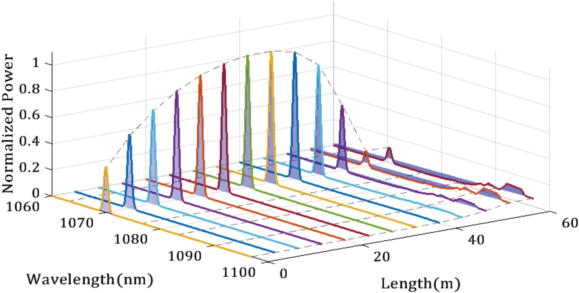
Figure 11. Generation of the new laser wavelength (the forward pump power is 1800 W).
6 Experiment of the second-order Raman fiber laser
To increase the Raman gain coefficient and produce a second- or higher-order Raman laser, we spliced another GDF after the gain fiber, as shown in Figure 12. The core and cladding diameters of the GDF were 25 and $400~\unicode[STIX]{x03BC}\text{m}$
, respectively, identical to the gain fiber. Figure 13 presented the output spectra when the length of the GDF was 50, 70, 80 and 100 m.
$400~\unicode[STIX]{x03BC}\text{m}$
, respectively, identical to the gain fiber. Figure 13 presented the output spectra when the length of the GDF was 50, 70, 80 and 100 m.

Figure 12. Experimental setup when the GDF is spliced after the YDF.

Figure 13. Output spectra and total power ( $P$
) at different lengths (LG) of splicing GDF: LG,
$P$
) at different lengths (LG) of splicing GDF: LG, $P$
are (a) 50 m, 3900 W, (b) 70 m, 3610 W, (c) 80 m, 3300 W and (d) 100 m, 2440 W, respectively.
$P$
are (a) 50 m, 3900 W, (b) 70 m, 3610 W, (c) 80 m, 3300 W and (d) 100 m, 2440 W, respectively.
Figure 13(a) indicated that the first-order Raman laser was still dominant when the GDF length is 50 m. As the length of the GDF increases, the second-order Raman laser will replace the dominance of the first-order Raman laser. While the GDF was 70 m, as shown in Figure 13(b), the center wavelengths of the first-, second- and third-order stimulated Raman lasers were 1122.5, 1182.7 and 1243.3 nm, respectively. In addition, the output power of the second-order Raman laser was about 1500 W, which accounts only for 45% of the total 3610 W output power. The 3 dB spectral width of the 1182.7 nm second-order Raman fiber was 14 nm. However, the power of the second-order Raman laser was only approximately 5 dB higher than that of the first- or third-order Raman laser. For future work, to obtain a second-order Raman laser and suppress other-order Raman lasers, we are preparing to optimize the length of the YDF and GDF, and inject a seed comprising a 1070 and 1180 nm laser into the amplifier.
7 Conclusions
In this paper, we presented both the experimental realization and theoretical analysis of a 3.7 kW, 1123 nm Raman fiber laser system. The system adopted a dual-wavelength bidirectional pumping configuration, consisting of 1018 nm YDFLs and 976 nm LDs as the forward and backward pump sources, respectively. The usage of long-wavelength pump sources reduced the thermal effect caused by quantum defects. A 60-m-long, 25/400- $\unicode[STIX]{x03BC}\text{m}$
YDF was employed as the Raman gain medium. The maximum output power was 3700 W while 4200 W of forward pump power and 2510 W of backward pump power were injected into the amplifier. The 3 dB spectral width of the 1123 nm Raman laser was 6.8 nm. The backward Raman laser power was 65 W with a 3 dB spectral width of 5.2 nm. Under a pump power of 3020 W, the
$\unicode[STIX]{x03BC}\text{m}$
YDF was employed as the Raman gain medium. The maximum output power was 3700 W while 4200 W of forward pump power and 2510 W of backward pump power were injected into the amplifier. The 3 dB spectral width of the 1123 nm Raman laser was 6.8 nm. The backward Raman laser power was 65 W with a 3 dB spectral width of 5.2 nm. Under a pump power of 3020 W, the $M^{2}$
factor of the output laser was measured to be 2.18. In addition, we proposed a multi-frequency model based on the steady-state rate equation. Taking the spectrum of the Raman gain and ASE into account, our model can resolve the spectra and power evolutions in both the forward and backward directions along the fiber. The numerical simulation results were in good agreement with the experimental results. The appearance of a new peak at about 1095 nm was also investigated theoretically and experimentally. Furthermore, a 1500 W, 1187 nm second-order Raman laser was obtained by splicing another 70 m GDF after the YDF. The power scaling of the second-order Raman laser will be studied in future work.
$M^{2}$
factor of the output laser was measured to be 2.18. In addition, we proposed a multi-frequency model based on the steady-state rate equation. Taking the spectrum of the Raman gain and ASE into account, our model can resolve the spectra and power evolutions in both the forward and backward directions along the fiber. The numerical simulation results were in good agreement with the experimental results. The appearance of a new peak at about 1095 nm was also investigated theoretically and experimentally. Furthermore, a 1500 W, 1187 nm second-order Raman laser was obtained by splicing another 70 m GDF after the YDF. The power scaling of the second-order Raman laser will be studied in future work.
Acknowledgements
This work was supported in part by the National Natural Science Foundation of China (Nos. 61675114 and 61875103) and the Tsinghua University Initiative Scientific Research Program (No. 20151080709).


 Open access