


1 Introduction
Coherent beam combining (CBC) of fiber lasers has great potential in breaking through the power limitation of a single laser beam while maintaining good beam quality – a topic that has been widely studied during the past decades[Reference Fan1–Reference Liu, Ma, Su, Tao, Ma, Wang and Zhou8]. In general, CBC techniques can be divided into two categories: filled aperture combining and tiled aperture combining[Reference Fan1]. Tiled aperture coherent combining has advantages in the development of combined numbers, and has achieved remarkable results in the past[Reference Bourderionnet, Bellanger, Primot and Brignon9, Reference Kabeya, Kermène, Fabert, Benoist, Saucourt, Desfarges-Berthelemot and Barthélémy10]. It also shows great potential in new frontiers such as high-power structured light generation[Reference Zhi, Hou, Ma, Ma, Zhou, Tao, Wang and Si11]. In high-power tiled aperture CBC systems, especially during operation with serious thermal and experimental fluctuations, dynamic phase noise always occurs and affects the performance of the combined beam. To eliminate the influence of dynamic phase noise and achieve constructive interference in the far-field, the relative phase of each array element should be accurately controlled. For actively phase-locked arrays, several approaches have been proposed and efficiently implemented, including heterodyne detection[Reference Anderegg, Brosnan, Cheung, Epp, Hammons, Komine, Weber and Wickham12], multi-dithering and single-frequency dithering techniques[Reference Shay13–Reference Jiang, Su, Zhang, Ma, Wang and Zhou17], interferometric techniques[Reference Antier, Bourderionnet, Larat, Lallier, Lenormand, Primot and Brignon18], phase-intensity mapping[Reference Kabeya, Kermene, Fabert, Benoist, Desfarges-Berthelemot and Barthelemy19] and the stochastic parallel gradient descent (SPGD) algorithm[Reference Zhou, Liu, Wang, Ma, Ma and Xu4, Reference Vorontsov and Sivokon20]. Along with simultaneous increase of combined numbers and output power, the control bandwidth of the phase controller is a serious issue that should be considered carefully[Reference Ahn and Kong21]. Investigations in improving the control bandwidth have been an ongoing effort since various phase control methods were proposed.
To further improve the control bandwidth, a fast and accurate phase extraction method is always necessary. As a result of their excellent real-time performance, machine learning and artificial intelligence algorithms may offer a route to further improve the phase control speed in CBC systems, which needs to be investigated carefully. In fact, this new technique has been successfully applied to many optical research fields, such as mode-locked lasers, optical microscopy and laser mode decomposition[Reference Fu, Brunton and Kutz22–Reference An, Huang, Li, Leng, Yang and Zhou25]. Quite recently, it has been reported that deep reinforcement learning methods could be used in Mach–Zehnder interferometer CBC structures[Reference Tünnermann and Shirakawa26]. As for the tiled aperture CBC technique that involves more combined channels, a feasible machine learning method is greatly required. There is an intuitive idea that constructing a deep learning (DL) network to learn the relationship between the intensity profile of the combined beam and the relative phases of array elements would solve this. In theory, by analyzing the real-time collected intensity profile based on the network, the phase error of the beam array could be estimated and compensated directly. However, one significant difficulty encountered is that there is no one-to-one correspondence between the far-field intensity profile of the combined beam and the relative phases of the array elements; thus the DL network would lose its effectiveness due to data collision. Recently, the concept of extracting cost functions at the non-focal-plane has been proposed by our group[Reference Hou, Zhang, Chang, Ma, Su, Wu, Ma and Zhou27]. Drawing on this concept, the primary difficulty in incorporating the DL method into the tiled aperture CBC technique could expect to be solved.
In this paper, we present a DL-based phase control method for tiled aperture coherent beam combining systems. To avoid the data collision mentioned above, non-focal-plane intensity profiles of the combined beam are used as training samples. We construct and train a convolutional neural network (CNN) for real-time estimation of the relative phases of the array elements, and the estimated phase error could be compensated by a servo phase control system. Such a direct phase compensation method does not cause an increase in complexity of the CBC system as the number of array elements increases, and it is compatible with optimization algorithms and dithering techniques. Our simulations are performed in detail to demonstrate the feasibility and extensibility of the proposed phase control technique, which has potential in improving the phase control bandwidth of CBC systems.
2 Principle and method
Figure 1 shows the experimental setup that could be used to implement the DL-based phase control method. The linearly polarized seed laser (SL) is amplified by a pre-amplifier (PA), and is then split into multiple channels by a fiber splitter (FS). The laser beam of each channel passes through a fiber phase modulator (FPM) and cascaded fiber amplifiers (FAs) for power scaling. Subsequently, the laser beams are emitted through a collimator array and propagate in free space. The collimated beam array is split into two parts by a highly reflective mirror (HRM). The transmitted part propagates through another HRM and a focus lens (FL), and is then sampled by a beam splitter (BS) to feed the phase control system at the non-focal-plane and observe the far-field intensity profile at the focal plane. The intensity profile of the combined beam collected by the CCD located at the non-focal-plane is sent to an FPGA controller carrying a well-trained CNN to estimate the phase error of the CBC system. Then, according to the outputs of the CNN, the FPGA controller applies control voltages to the FPMs to compensate the estimated phase error and achieve phase locking.
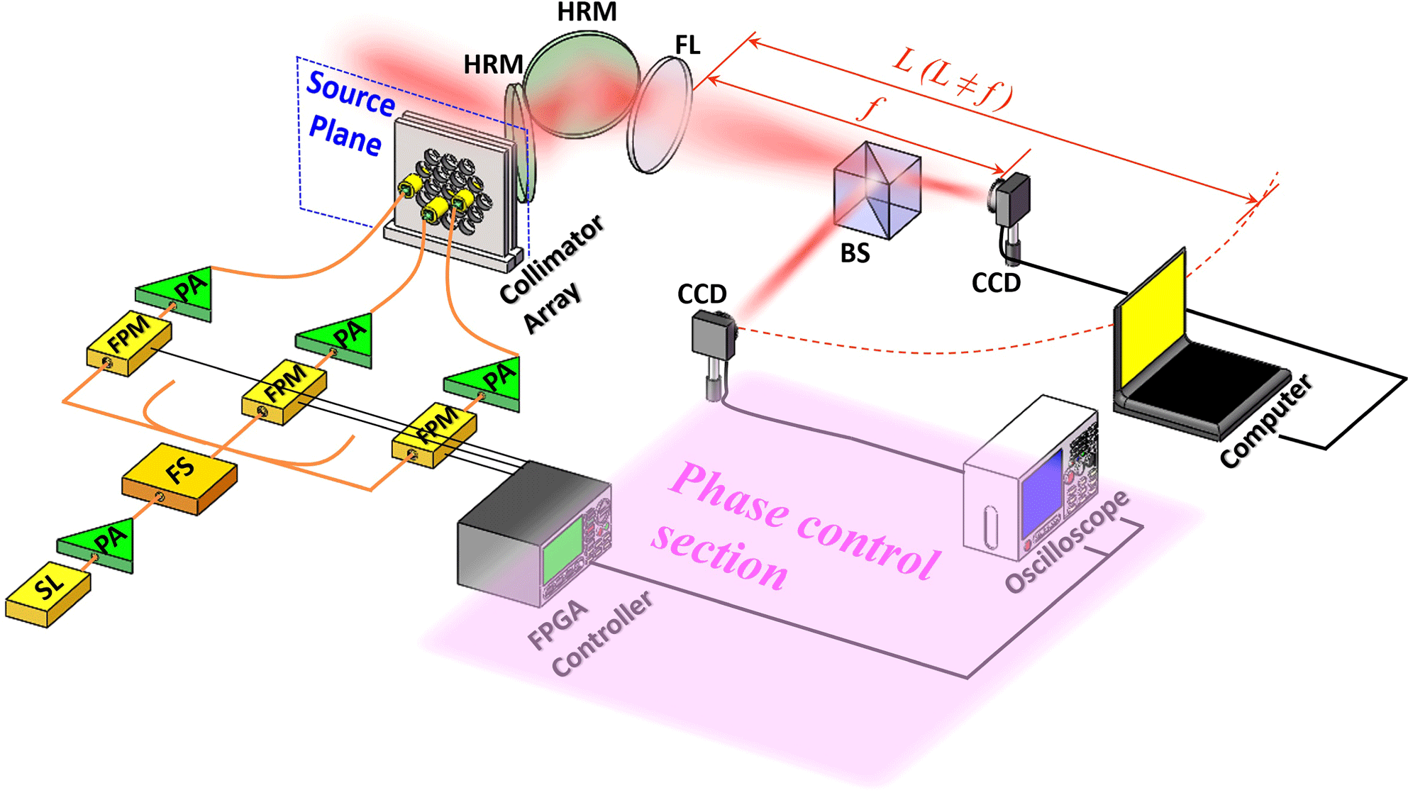
Figure 1. Experimental setup for implementing the DL-based phase control method for CBC. (SL: seed laser; PA: pre-amplifier; FS: fiber splitter; FPM: fiber phase modulator; FA: fiber amplifier; HRM: highly reflective mirror; FL: focus lens; BS: beam splitter.)
The electric field of an $N$
-element linearly polarized fundamental mode Gaussian beam array at the source plane can be expressed as
$N$
-element linearly polarized fundamental mode Gaussian beam array at the source plane can be expressed as
 $$\begin{eqnarray}\displaystyle E(\unicode[STIX]{x1D746},z=0) & = & \displaystyle \mathop{\sum }_{j=1}^{N}A_{0}\exp \left[-\frac{(\unicode[STIX]{x1D746}-\unicode[STIX]{x1D746}_{\boldsymbol{j}})^{2}}{{w_{0}}^{2}}\right]\nonumber\\ \displaystyle & & \displaystyle \times \,\text{circ}\left(\frac{|\unicode[STIX]{x1D746}-\unicode[STIX]{x1D746}_{\boldsymbol{j}}|}{d/2}\right)\exp (i\unicode[STIX]{x1D711}_{j}),\end{eqnarray}$$
where $A_{0}$
,
$A_{0}$
, $w_{0}$
,
$w_{0}$
, $\unicode[STIX]{x1D711}_{j}$
and
$\unicode[STIX]{x1D711}_{j}$
and $d$
are the amplitude, waist width, initial phase and aperture diameter of the
$d$
are the amplitude, waist width, initial phase and aperture diameter of the $j$
th beamlet, respectively.
$j$
th beamlet, respectively. $\unicode[STIX]{x1D746}=\boldsymbol{x}\hat{\boldsymbol{x}}+\boldsymbol{y}\hat{\boldsymbol{y}}$
, and
$\unicode[STIX]{x1D746}=\boldsymbol{x}\hat{\boldsymbol{x}}+\boldsymbol{y}\hat{\boldsymbol{y}}$
, and $\unicode[STIX]{x1D746}_{\boldsymbol{j}}=\boldsymbol{x}_{\boldsymbol{j}}\hat{\boldsymbol{x}}+\boldsymbol{y}_{\boldsymbol{j}}\hat{\boldsymbol{y}}$
represents the position vector of the
$\unicode[STIX]{x1D746}_{\boldsymbol{j}}=\boldsymbol{x}_{\boldsymbol{j}}\hat{\boldsymbol{x}}+\boldsymbol{y}_{\boldsymbol{j}}\hat{\boldsymbol{y}}$
represents the position vector of the $j$
th beamlet. Under the paraxial approximation, the intensity profile of the combined beam can be represented in the Fourier transform form as
$j$
th beamlet. Under the paraxial approximation, the intensity profile of the combined beam can be represented in the Fourier transform form as
 $$\begin{eqnarray}I(\boldsymbol{r},z=L)=\left|\frac{e^{i(k/2L)\boldsymbol{r}^{2}}}{i\unicode[STIX]{x1D706}L}{\mathcal{F}}\{E(\unicode[STIX]{x1D746},z=0)e^{i(k/2)(1/L-1/f)\unicode[STIX]{x1D746}^{2}}\}\right|^{2},\end{eqnarray}$$
where $\boldsymbol{r}$
denotes the position vector at the receiver plane.
$\boldsymbol{r}$
denotes the position vector at the receiver plane. $\unicode[STIX]{x1D706}$
,
$\unicode[STIX]{x1D706}$
, $f$
and
$f$
and $L$
account for the wavelength, focal length and propagating distance, respectively.
$L$
account for the wavelength, focal length and propagating distance, respectively. ${\mathcal{F}}\{\boldsymbol{\cdot }\}$
denotes the Fourier-transform operation. Note that the distance between the collimator array and the focus lens is far less than
${\mathcal{F}}\{\boldsymbol{\cdot }\}$
denotes the Fourier-transform operation. Note that the distance between the collimator array and the focus lens is far less than $f$
and
$f$
and $L$
. The intensity profiles of the receiver plane are input into the CNN for previous training and real-time phase error compensation. To avoid data collision, the receiver plane is set at the non-focal-plane (
$L$
. The intensity profiles of the receiver plane are input into the CNN for previous training and real-time phase error compensation. To avoid data collision, the receiver plane is set at the non-focal-plane ( $L\neq f$
), where the peak intensity of the sidelobes is comparable to the peak intensity of the main lobe.
$L\neq f$
), where the peak intensity of the sidelobes is comparable to the peak intensity of the main lobe.
The CNN performing in our phase control scheme is modified from the VGG-16 model[Reference Simonyan and Zisserman28], as shown in Figure 2. The model is modified based on the input and output of the network. Concretely, the filter size of the first convolutional layer of the VGG model is changed from $3\times 3\times 3$
to
$3\times 3\times 3$
to $3\times 3\times 1$
, as our input is a single intensity pattern image. The ReLU function is chosen for nonlinear activation after each convolutional layer, followed by max pooling[Reference Simonyan and Zisserman28]. The Softmax function after the last fully connected (FC) layer of the original VGG model is replaced by the Sigmoid function. The reason for this substitution is that estimating the relative phases of the array elements is a regression problem. Compared with the Softmax function, which is usually applied to distribute images to certain categories for classification tasks, the Sigmoid function can achieve better performance for regression problems. It should be noted that the convolution layer, max pooling layer and fully connected layer in our network have their particular functions. The convolution layer extracts certain features from the input image through its filters, while the max pooling layer removes redundant information to greatly decrease the computational cost. The fully connected layer converts the output of previous layers into a one-dimensional vector, which is related to the estimated result. The network learns to estimate relative phase from a single intensity pattern with these layers. The intensity patterns are generated by randomly changing the relative phase of each element as the samples for training. Then, due to the Sigmoid function before the output, the phase vector with
$3\times 3\times 1$
, as our input is a single intensity pattern image. The ReLU function is chosen for nonlinear activation after each convolutional layer, followed by max pooling[Reference Simonyan and Zisserman28]. The Softmax function after the last fully connected (FC) layer of the original VGG model is replaced by the Sigmoid function. The reason for this substitution is that estimating the relative phases of the array elements is a regression problem. Compared with the Softmax function, which is usually applied to distribute images to certain categories for classification tasks, the Sigmoid function can achieve better performance for regression problems. It should be noted that the convolution layer, max pooling layer and fully connected layer in our network have their particular functions. The convolution layer extracts certain features from the input image through its filters, while the max pooling layer removes redundant information to greatly decrease the computational cost. The fully connected layer converts the output of previous layers into a one-dimensional vector, which is related to the estimated result. The network learns to estimate relative phase from a single intensity pattern with these layers. The intensity patterns are generated by randomly changing the relative phase of each element as the samples for training. Then, due to the Sigmoid function before the output, the phase vector with $N-1$
elements is linearly scaled to [0, 1], by dividing by
$N-1$
elements is linearly scaled to [0, 1], by dividing by $2\unicode[STIX]{x1D70B}$
, as a label of the corresponding pattern.
$2\unicode[STIX]{x1D70B}$
, as a label of the corresponding pattern.
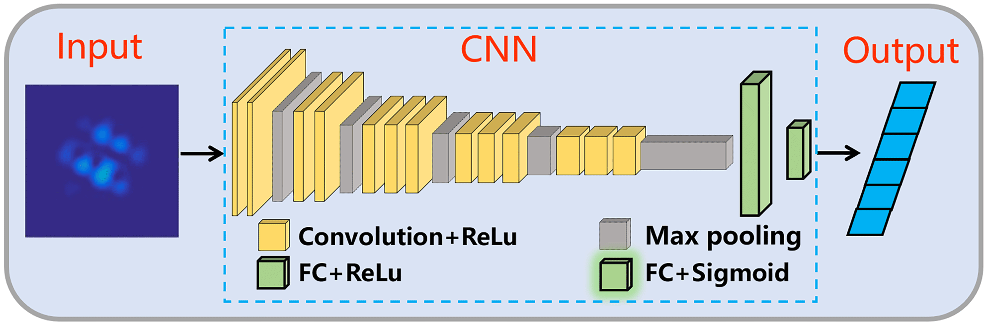
Figure 2. Illustration of the CNN for estimating the phase error in CBC systems.
In the training procedure, the input images pass through the layers of the CNN and are regressed into an output vector with $N-1$
elements. The loss of our network is defined as the mean-square error (MSE) between the output and the label vector. The MSE of the
$N-1$
elements. The loss of our network is defined as the mean-square error (MSE) between the output and the label vector. The MSE of the $n$
th sample is expressed as
$n$
th sample is expressed as
 $$\begin{eqnarray}\text{MSE}(n)=\frac{1}{N-1}\mathop{\sum }_{j=1}^{N-1}(y_{o}^{(n)}[j]-y_{l}^{(n)}[j])^{2},\end{eqnarray}$$
where $y_{o}$
and
$y_{o}$
and $y_{l}$
denote the output and the label vector of the CNN, respectively. Then, the parameters of the CNN are updated iteratively using back-propagated gradients based on the MSE loss. In our simulated research, the samples are trained on a desktop computer with an Intel Core i7-8700 CPU and GTX 1080 GPU.
$y_{l}$
denote the output and the label vector of the CNN, respectively. Then, the parameters of the CNN are updated iteratively using back-propagated gradients based on the MSE loss. In our simulated research, the samples are trained on a desktop computer with an Intel Core i7-8700 CPU and GTX 1080 GPU.
When the network reaches convergence after several training epochs, it can be used to estimate the relative phase of each array element. Taking an intensity pattern image as input, the CNN outputs a vector with $N-1$
elements, from which the estimated relative phases can be obtained by multiplying
$N-1$
elements, from which the estimated relative phases can be obtained by multiplying $2\unicode[STIX]{x1D70B}$
. Based on the relative phases estimated by the CNN, the phase error in the CBC system could be compensated directly.
$2\unicode[STIX]{x1D70B}$
. Based on the relative phases estimated by the CNN, the phase error in the CBC system could be compensated directly.
3 Numerical simulation results and discussion
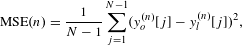
In order to demonstrate the feasibility and extensibility of the DL-based phase control method, we investigate the coherent combining of 7-element and 19-element hexagonal arrays as examples, and numerical simulations are performed in detail. The arrangements of the beam arrays are shown in Figures 3(a) and 3(b), respectively. The parameters of the array elements $w_{0}$
,
$w_{0}$
, $d$
and
$d$
and $\unicode[STIX]{x1D706}$
are assumed to be 23 mm, 10.24 mm and
$\unicode[STIX]{x1D706}$
are assumed to be 23 mm, 10.24 mm and $1.06~\unicode[STIX]{x03BC}\text{m}$
, respectively. The focal length is 20 m, while the distances of the non-focal-planes behind the focal plane for the 7-element and 19-element array cases are optimized as 0.6 m and 0.4 m, respectively, according to our previous theoretical analysis[Reference Hou, Zhang, Chang, Ma, Su, Wu, Ma and Zhou27].
$1.06~\unicode[STIX]{x03BC}\text{m}$
, respectively. The focal length is 20 m, while the distances of the non-focal-planes behind the focal plane for the 7-element and 19-element array cases are optimized as 0.6 m and 0.4 m, respectively, according to our previous theoretical analysis[Reference Hou, Zhang, Chang, Ma, Su, Wu, Ma and Zhou27].
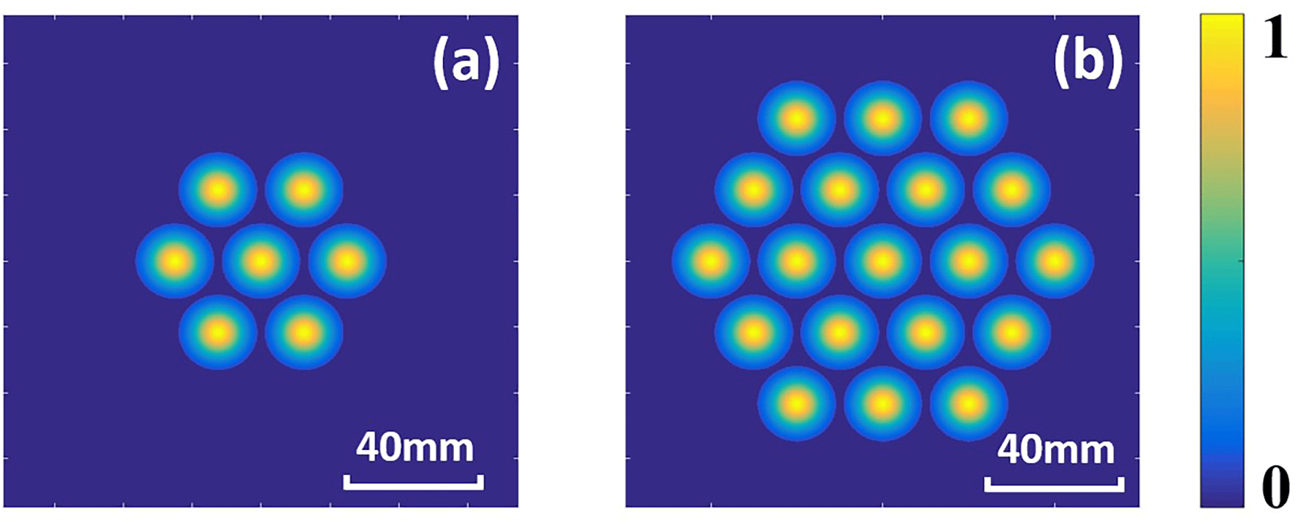
Figure 3. Intensity profiles of the beam arrays consisting of (a) 7 elements and (b) 19 elements.
First, the necessity of constructing the CNN at the non-focal-plane should be illustrated. In training a DL network, if the input image corresponds to multiple labels, it would cause data collision, which means that the constructed DL network would lose its efficiency. In our previous work, we have indicated that the same far-field intensity profile of a symmetrical beam array could correspond to different phase distributions in the near field[Reference Hou, Zhang, Chang, Ma, Su, Wu, Ma and Zhou27]. Here, we will explain how this problem affects the accuracy of the DL network.
Without loss of generality, we take the 7-element hexagonal array shown in Figure 3(a) as an example. The CNNs are trained for 30 epochs with the prepared samples at the focal plane and the non-focal-plane. These samples are acquired randomly from simulation and the number of the samples is 100,000, which is same for the non-focal-plane case and the focal plane case, respectively. To analyze the convergence of the training process, 1000 testing samples have been generated randomly. The calculated average MSE values of the 1000 testing samples after every training epoch are shown in Figure 4, in which the red curve with triangle markers and the blue curve with square markers represent the non-focal-plane case and the focal plane case, respectively. Note that the MSE of the non-focal-plane case decreases from about 0.011 at the first epoch to about 0.002 at the final epoch, showing the high prediction accuracy of the convergent CNN. In contrast, the MSE of the focal plane case fluctuates around 0.082 in the training process, indicating the focal-plane-constructed CNN cannot achieve convergence.
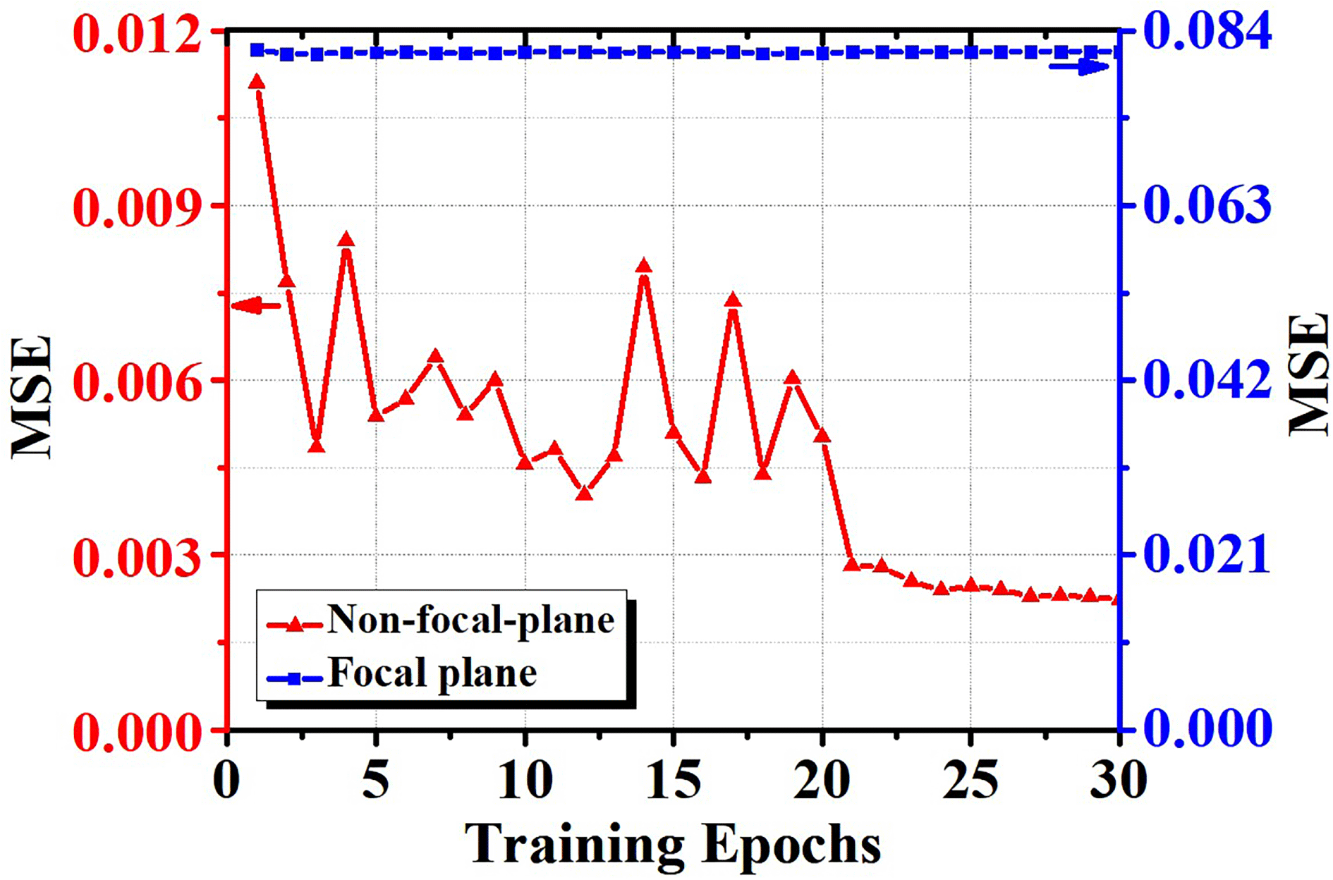
Figure 4. Average MSE of the CNN as a function of the number of training epochs.
Figure 5. Performances of the trained CNN for phase control. Far-field intensity profiles (a1)–(a5) without phase error compensation, and with phase error compensation using CNNs trained at (b1)–(b5) the focal plane and (c1)–(c5) the non-focal-plane.
To further evaluate the performances of the CNNs trained after 30 training epochs, we have tested the far-field intensity profiles of the combined beams using the 1000 testing samples mentioned above. Figure 5 shows a comparison in the performances of the CNNs trained by intensity profiles of the non-focal-plane and the focal plane. If the intensity profiles of the focal plane are used to train the CNN previously, the far-field energy concentration of the phase compensated combined beam (Figures 5(b1)–5(b5)) is significantly lower than in the case of using the non-focal-plane (Figures 5(c1)–5(c5)). In other words, the CNN trained at the non-focal-plane could reflect the phase distribution of the beam array at the source plane more accurately. The results of the 1000 times simulation show that the average on-axis far-field intensity of the phase-compensated combined beams in the case of using the CNN constructed at the focal plane is approximately half of that in the case of the non-focal-plane. Hence, fully considering the convergence of the training process and the accuracy of the trained CNN, the DL-based phase control system should be fed at the non-focal-plane.
Then, to demonstrate the feasibility of the DL-based phase control method, we simulate the far-field intensity profiles of the hexagonal beam arrays displayed in Figure 3 for the incoherent combining (without phase error compensation) and DL-based coherent combining (with DL-based phase compensation) cases. The case of ideal coherent combining, which means that the array elements are monochromatic and phase-matched, is also shown for a full comparison. For the coherent combining of the 7-element and 19-element arrays, 500 randomly generated phase errors are applied to the beam array for each case. Correspondingly, we investigate the efficiency of beam combining based on the average far-field intensity profile of the 500 times simulation. To evaluate the performance of the DL-based phase control method, key metrics such as Strehl ratio (SR), fringe contrast and power in the bucket (PIB) of the phase-compensated combined beams are calculated in detail for different beam arrays[Reference Zhou, Liu, Wang, Ma, Ma and Xu4, Reference Vorontsov and Lachinova29, Reference Lachinova and Vorontsov30]. The SR is defined as the ratio of the on-axis intensity of a beam to that of an equal-power flat-top beam illuminating the same aperture. Fringe contrast is defined by the formula $(I_{\text{max}}-I_{\text{min}})/(I_{\text{max}}+I_{\text{min}})$
, where
$(I_{\text{max}}-I_{\text{min}})/(I_{\text{max}}+I_{\text{min}})$
, where $I_{\text{max}}$
and
$I_{\text{max}}$
and $I_{\text{min}}$
denote the maximum intensity and the adjacent minimum on the far-field intensity distribution, respectively. PIB describes the energy encircled in an on-axis circular area at the receiver plane. The values of the metrics are determined by the residual phase error; thus these useful metrics could reflect the accuracy of the phase control method.
$I_{\text{min}}$
denote the maximum intensity and the adjacent minimum on the far-field intensity distribution, respectively. PIB describes the energy encircled in an on-axis circular area at the receiver plane. The values of the metrics are determined by the residual phase error; thus these useful metrics could reflect the accuracy of the phase control method.
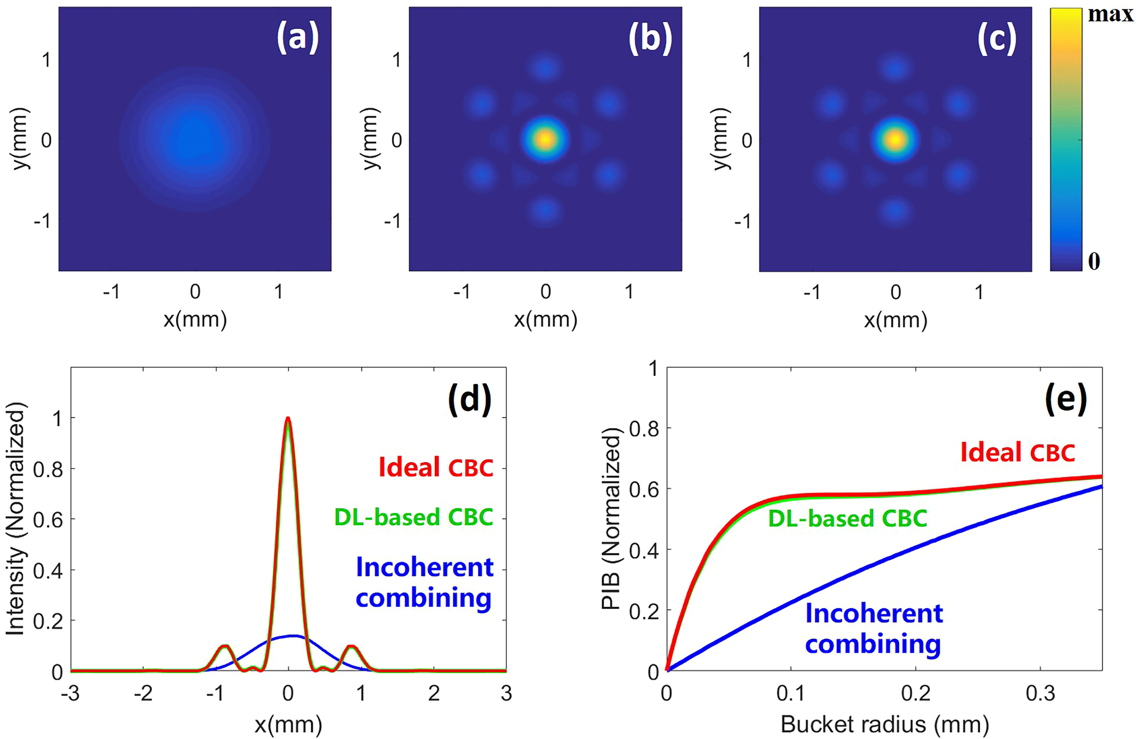
Figure 6. Far-field intensity profiles of the (a) incoherently combined beam, (b) DL-based coherently combined beam and (c) ideal coherently combined beam, for the case of the 7-element hexagonal array. (d) Far-field intensity profiles along the $x$
axis for the ideal coherently combined beam (red), DL-based coherently combined beam (green) and incoherently combined beam (blue). (e) Power in the bucket (PIB) at the focal plane as a function of the bucket radius for the ideal coherently combined beam (red), DL-based coherently combined beam (green) and incoherently combined beam (blue).
$x$
axis for the ideal coherently combined beam (red), DL-based coherently combined beam (green) and incoherently combined beam (blue). (e) Power in the bucket (PIB) at the focal plane as a function of the bucket radius for the ideal coherently combined beam (red), DL-based coherently combined beam (green) and incoherently combined beam (blue).
Figure 6 shows the performance of the DL-based phase control method for the 7-element hexagonal array. Figures 6(a)–6(c) show the average two-dimensional intensity distributions of the incoherently combined beam, DL-based coherently combined beam and ideal coherently combined beam at the focal plane, respectively. The incoherently combined beam spreads significantly and has a larger spot size than the DL-based coherently combined beam, which resembles the ideal coherently combined beam. Both the ideal coherently combined beam and DL-based coherently combined beam have far-field intensity profiles of concentrated energy, and the fringe contrasts are calculated as 1 and 0.998, respectively. Figure 6(d) presents the average far-field intensity profiles along the $x$
axis. The red, green and blue dashed lines denote the ideal coherently combined beam, DL-based coherently combined beam and incoherently combined beam, respectively. The SR of the DL-based combined beam, which is approximately 0.98 of that of the ideal coherently combined beam, is almost 6.99 times greater than the SR of the combined beam without phase compensation. The normalized PIB of the combined beams at the focal plane as a function of the bucket radius is calculated, as shown in Figure 6(e). The radius of the central lobe of the ideal coherently combined beam (red) and the DL-based coherently combined beam (green) is approximately 0.26 mm, and the normalized PIBs for the ideal coherently combined beam, the DL-based coherently combined beam and the incoherently combined beam (blue) at a radius of 0.26 mm are calculated as 0.61, 0.61 and 0.49, respectively.
$x$
axis. The red, green and blue dashed lines denote the ideal coherently combined beam, DL-based coherently combined beam and incoherently combined beam, respectively. The SR of the DL-based combined beam, which is approximately 0.98 of that of the ideal coherently combined beam, is almost 6.99 times greater than the SR of the combined beam without phase compensation. The normalized PIB of the combined beams at the focal plane as a function of the bucket radius is calculated, as shown in Figure 6(e). The radius of the central lobe of the ideal coherently combined beam (red) and the DL-based coherently combined beam (green) is approximately 0.26 mm, and the normalized PIBs for the ideal coherently combined beam, the DL-based coherently combined beam and the incoherently combined beam (blue) at a radius of 0.26 mm are calculated as 0.61, 0.61 and 0.49, respectively.
To further illustrate the extensibility of the DL-based phase control method, the CNN for the 19-element hexagonal array is constructed and the phase control performance is studied by simulation, as shown in Figure 7. Figures 7(a)–7(c) exhibit the average far-field intensity profiles of the incoherently combined beam, DL-based coherently combined beam and ideal coherently combined beam, respectively. Comparing the average intensity distributions of the combined beams, the advantage of the DL-based coherently combined beam (which resembles the ideal coherently combined beam) over the incoherently combined beam could be clearly observed. The fringe contrasts of the ideal coherently combined beam and DL-based coherently combined beam are calculated as 1 and 0.992, respectively. Figure 7(d) presents the average intensity profiles of the ideal coherently combined beam (red), DL-based coherently combined beam (green) and incoherently combined beam (blue) along the $x$
axis at the focal plane. The SRs of the DL-based combined beam and the incoherently combined beam are approximately 0.84 and 0.05 of that of the ideal coherently combined beam. The normalized PIB as a function of radius for the ideal coherent combining (red), DL-based coherent combining (green) and incoherent combining (blue) cases is shown in Figure 7(e). At a radius of 0.15 mm (the radius of the central lobe of the ideal coherently combined beam), the normalized PIBs for the ideal coherently combined beam, the DL-based coherently combined beam and the incoherently combined beam are calculated as 0.62, 0.58 and 0.32, respectively.
$x$
axis at the focal plane. The SRs of the DL-based combined beam and the incoherently combined beam are approximately 0.84 and 0.05 of that of the ideal coherently combined beam. The normalized PIB as a function of radius for the ideal coherent combining (red), DL-based coherent combining (green) and incoherent combining (blue) cases is shown in Figure 7(e). At a radius of 0.15 mm (the radius of the central lobe of the ideal coherently combined beam), the normalized PIBs for the ideal coherently combined beam, the DL-based coherently combined beam and the incoherently combined beam are calculated as 0.62, 0.58 and 0.32, respectively.
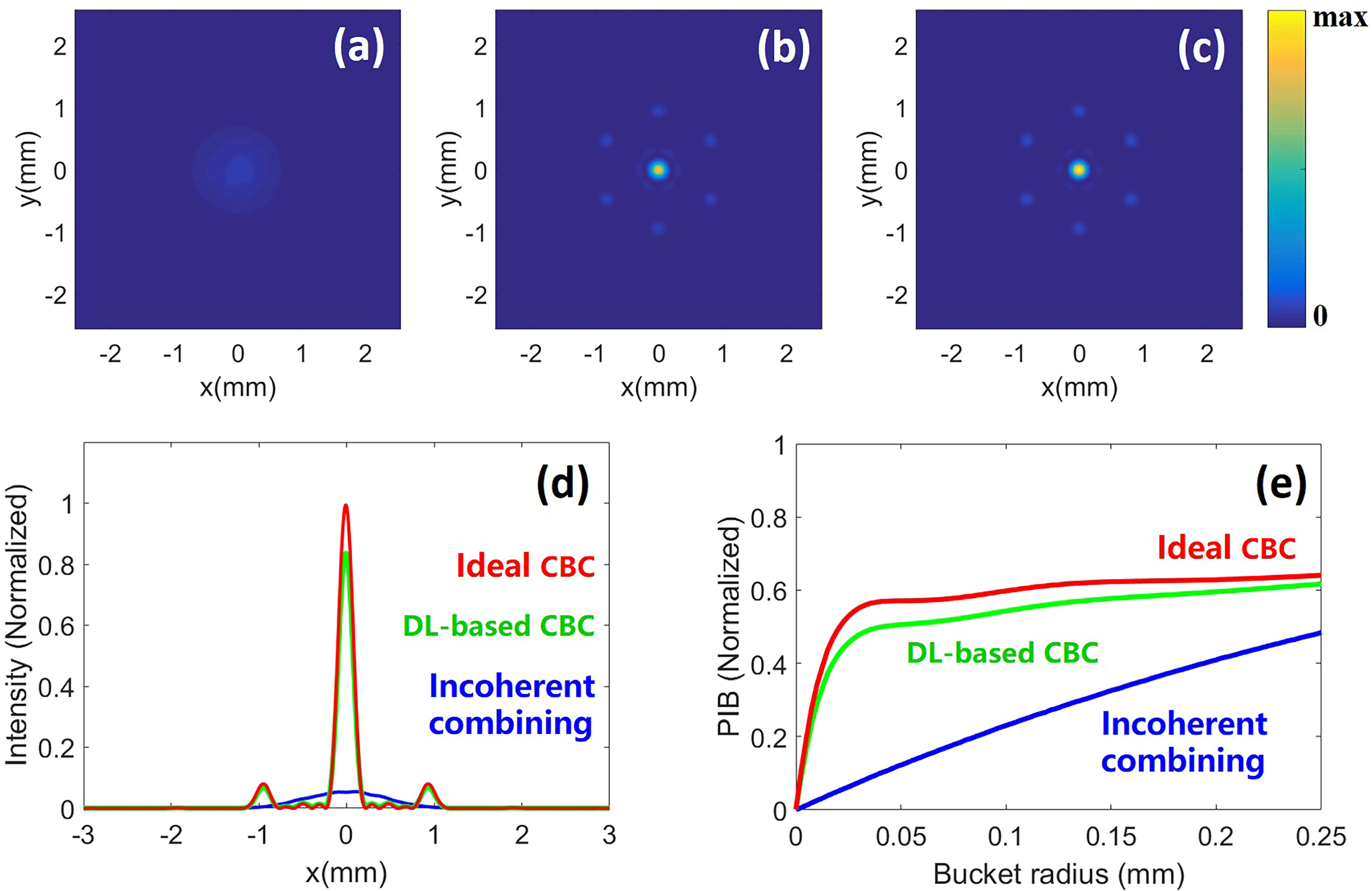
Figure 7. Far-field intensity profiles of the (a) incoherently combined beam, (b) DL-based coherently combined beam and (c) ideal coherently combined beam, for the case of the 19-element hexagonal array. (d) Far-field intensity profiles along the $x$
axis for the ideal coherently combined beam (red), DL-based coherently combined beam (green) and incoherently combined beam (blue). (e) Power in the bucket (PIB) at the focal plane as a function of the bucket radius for the ideal coherently combined beam (red), DL-based coherently combined beam (green) and incoherently combined beam (blue).
$x$
axis for the ideal coherently combined beam (red), DL-based coherently combined beam (green) and incoherently combined beam (blue). (e) Power in the bucket (PIB) at the focal plane as a function of the bucket radius for the ideal coherently combined beam (red), DL-based coherently combined beam (green) and incoherently combined beam (blue).
In summary, the phase error in the CBC system could be efficiently estimated and compensated based on the DL network. Compared to the case of incoherent combining, the DL-based phase control method for coherent combining could improve the far-field energy concentration of the combined beam significantly. The most significant advantage of the DL-based phase control method is time efficiency. It can perform non-iterative phase control with a pre-trained CNN. When more array elements are involved, the DL-based phase control method consumes the same amount of time as the fewer-elements-involved cases. Although a slight decrease in the accuracy of the CNN along with the increasing number of array elements could be observed, which is caused by the increase in complexity of the non-focal-plane intensity profile, this difficulty is expected to be solved by optimizing the CNN structure, increasing the number of training samples, and the assistance of optimization algorithms (such as SPGD algorithm)[Reference An, Huang, Li, Leng, Yang and Zhou25].
4 Conclusion
In this paper, we have shown that the DL-based phase control method could be implemented into CBC systems to directly compensate the phase error. Comprehensively considering simulation results for the convergence of the training process and the accuracy of the trained CNN, we have shown that, different from conventional active phase control methods, the DL-based servo phase control system should be fed at the non-focal-plane. Using key metrics of the combined beams of 7-element and 19-element hexagonal arrays to evaluate the phase control performance, we have demonstrated that the DL-based phase control method is feasible and could be extended. With an increase in the number of array elements, the complexity of the DL-based phase control system and the computing time of the CNN did not increase; thus the DL-based phase control method offers an opportunity to improve the phase control bandwidth of CBC systems. By optimizing the network structure, and in conjunction with optimization algorithms, the difficulty of a slight decrease in accuracy as the number of array elements is increased is expected to be solved – a topic which deserves further study.
Acknowledgements
This work was supported by the National Natural Science Foundation of China (Nos. 61705264 and 61705265) and the Natural Science Foundation of Hunan Province, China (No. 2019JJ10005). The authors Tianyue Hou and Yi An contributed equally to this work.


 Open access