


Introduction
Conventional “bulk” metallic materials still dominate industrial applications, and common methods to study localized corrosion involve experiments with measurement areas in the cm2 to mm2 range. However, in to completely understand to understand the mechanisms of corrosion and interactions between specific microstructural features in or at the metal surface and the local environment, it is necessary to study the corrosion processes at high spatial resolution. At the same time, it is important not to dismiss the effects of bulk material entities such as grain boundaries, inclusions, fine-scale precipitates and/or defects. Several studies have been conducted to assess the electrochemical behavior of small regions (µm2 or nm2) in bulk samples. For example, Lohrengel (Reference Kestel2004), Böhni et al. (Reference Böhni, Suter and Assi2000), and Martin et al. (Reference Li, Nielsen and De Yoreo2008) all investigated materials via micro- or nanocapillary cells with an exposed area of several µm2 or nm2. This facilitated the study of localized corrosion, e.g. of single grains in welds, or single micron-sized particles in metal. Vogel & Schultze (Reference Schilling1999) combined a microcell and optical/laser microscope to investigate local reactions on the micrometer scale. A considerable disadvantage in those studies was that these measurements could not directly record the response or reaction on the surface as a function of time, such as the time-resolved response of a pit initiation or dissolved inclusion, because the detailed examination of the exposed areas were always performed after the electrochemical measurements.
There is now, increasingly, a desire to perform in situ studies on materials in order to understand the near real-time behavior of the surface interaction in a range of environments. In situ analytical transmission electron microscopy (TEM) in liquids has become an increasingly important and a dynamic research area as it allows the experimentalist observe many of the phenomena of interest in real time (de Jonge and Ross, Reference Pimblott and LaVerne2017). This re-emergence has become possible due to the advent of a new range of specialized, microfabricated in situ specimen TEM holders which include: liquid, electrochemical, heating, gaseous and tomographic analysis (Li et al., Reference Kasem2013; DENS, Reference Zeng, Liang, Chu and Zheng2016; Hummingbird Scientific, Reference Zheng, Claridge, Minor, Alivisatos and Dahmen2016; Protochips, Reference Zhong, Schilling, Zaluzec and Burke2016). In addition, the recent ability not only to simply image, but also to conduct hyperspectral elemental imaging in liquids or gases is particularly important when studying the localized interaction of the environment with specific microstructural features in metals and their alloys (Schilling et al., 2015; Prestatetal, Reference de Jonge and Ross2015).
In Situ Aqueous Studies: Background
To understand the electrochemical reaction of a metal from both a thermodynamic and kinetic perspective, it is essential to perform detailed examination of the interaction between a reaction surface and its surrounding liquid media. At the same time, it is also crucial to understand the investigation/characterization technique employed, as well as any associated factors which can affect the system during in situ studies. Specifically, the chemical and physical reactions, e.g. surface condition, specimen area, temperature, flow rate, and pH during any in situ experiments, together with any detrimental electron beam-induced effects, which may be realized in the aerated aqueous media. To explain this comprehensively is beyond the scope of this work; however, to understand the systematic protocols we have established for in situ electrochemical experiments, we will briefly review a compendium of factors which should be understood and controlled to the greatest extent possible in order to achieve reproducible electrochemical studies of corrosion in this new operating mode during in situ TEM.
In Situ Aqueous Studies: Corrosion Basics
Aqueous corrosion is an electrochemical process whereby electrons produced via anodic oxidation of a metal are consumed by an oxidant in the environment, such as dissolved oxygen, protons or H2O. During dissolution/corrosion, metal atoms leave the bulk material as ions. This process is an anodic oxidation reaction. The general case of a metal M undergoing oxidation is given by equation (1) and a specific example of iron illustrated by equation (2).
 $${\rm M}\to{\rm M}^{{{\rm n}{\plus}}} {\plus}{\rm ne}^{{\minus}} ,$$
 $${\rm Fe}\to{\rm Fe}^{{2{\plus}}} {\plus}2{\rm e}^{{\minus}} .$$
The parallel cathodic reaction, in which electrons are released during a metal oxidation event and are then consumed, is known as a reduction reaction and occurs at the surface of the cathode. Reduction processes can occur in many media and involve numerous species and these processes in aqueous solutions are illustrated by equations (3–6). In neutral aerated solutions, the reduction of dissolved oxygen [equation (5)] is the main cathodic process, whereas in acidic solutions proton reduction predominates [equation (4)]. The corrosion of iron in neutral H2O containing oxygen can be described by a combination of equation (2) and equation (5) which can be combined and yield equation (7).
 $$2{\rm e}^{{\minus}} {\plus}2{\rm H}_{2} {\rm O}\to{\rm H}_{2} {\plus}2{\rm OH}^{{\minus}} ,$$
 $$2{\rm e}^{{\minus}} {\plus}2{\rm H}_{3} {\rm O}^{{\plus}} \to{\rm H}_{2} {\plus}2{\rm H}_{2} {\rm O,}$$
 $$2{\rm e}^{{\minus}} {\plus}\raise.5ex\hbox{$\scriptstyle 1$}\kern-.1em/ \kern-.15em\lower.25ex\hbox{$\scriptstyle 2$} {\rm O}_{2} {\plus}{\rm H}_{2} {\rm O}\to2{\rm OH}^{{\minus}} ,$$
 $$2{\rm e}^{{\minus}} {\plus}\raise.5ex\hbox{$\scriptstyle 1$}\kern-.1em/ \kern-.15em\lower.25ex\hbox{$\scriptstyle 2$} {\rm O}_{2} {\plus}2{\rm H}_{3} {\rm O}^{{\plus}} \to3{\rm H}_{2} {\rm O,}$$
 $$2{\rm Fe}{\plus}{\rm O}_{2} {\plus}2{\rm H}_{2} {\rm O}\to2{\rm Fe}\left( {{\rm OH}} \right)_{2} .$$
The products produced during the dissolution of metals are also many and complex. For example, in the case of Fe, further oxidation of iron (II) species to form a variety of secondary corrosion products, such as iron (III) oxide, iron (III) hydroxides or iron (III)-oxide-hydroxide may occur. These reactions are described by reactions (8) through (10):
 $$2{\rm Fe}\left( {{\rm OH}} \right)_{2} {\plus}\raise.5ex\hbox{$\scriptstyle 1$}\kern-.1em/ \kern-.15em\lower.25ex\hbox{$\scriptstyle 2$} {\rm O}_{2} {\plus}{\rm H}_{2} {\rm O}\to2{\rm Fe }\left( {{\rm OH}} \right)_{3} ,$$
 $${\rm Fe}\left( {{\rm OH}} \right)_{{3 }} \to{\rm FeO}\left( {{\rm OH}} \right){\plus}{\rm H}_{2} {\rm O,}$$
 $$2{\rm FeO}\left( {{\rm OH}} \right){\plus}{\rm O}_{{2 }} \to{\rm Fe}_{2} {\rm O}_{3} {\plus}{\rm H}_{2} {\rm O}{\rm .}$$
The presence of other phases in Fe alloys, such nonmetallic MnS inclusions, will also react in oxygenated H2O as per reactions (11) through (12) (Wranglen, Reference Wendler-Kalsch and Gräfen1974):
 $${\rm MnS}{\plus}4{\rm H}_{2} {\rm O} \to{\rm Mn}^{{2{\plus}}} {\plus}{\rm SO}_{4} ^{{2{\minus}}} {\plus}8{\rm H}^{{\plus}} {\plus}8{\rm e}^{{\minus}} ,$$
 $$2{\rm O}_{2} {\plus}8{\rm H}^{{\plus}} {\plus}8{\rm e}^{{\minus}} \to4{\rm H}_{2} {\rm O}{\rm .}$$
The reaction of MnS inclusions in H2O will be addressed in Validation Experiments and Application to Austenitic Stainless Steel Sections, later in this paper.
To maintain electro-neutrality, anodic dissolution must be balanced by the reduction process and the current produced via both oxidation and reduction reactions must be equal. Corrosion is only thermodynamically feasible when the change in free energy ∆G<0, i.e. when the thermodynamic reversible potential of the cathodic process is greater than that of the anodic process.
By its nature, corrosion is an interfacial reaction of metal surfaces and liquid electrolyte and this region has been generally modeled as having three interaction layers. The first layer is electrolyte in contact with the metal surface and is termed the inner Helmholtz plane where the charged metal surface adsorbs dipole H2O molecules due to chemical interaction and behaves differently than the bulk electrolyte. The second layer is composed of ions attracted to the surface charge via the Coulomb force, electrically screening the first layer, and is called the outer Helmholtz plane. This second layer is loosely associated with the covered metal surface. These inner and outer Helmholtz layers are also called the “electrical double layer” and behave like a plain charged capacitor, and the potentials developed there in are used in part to characterize the electrochemical processes. Finally, a third or diffusion layer is made of free ions that move in the remaining electrolyte under the influence of electric attraction and thermal motion rather than being firmly anchored. This model describes the reaction of the metal surface in H2O and, importantly, the electrical potential here can be influenced by numerous factors especially the presence of any excess electrons which might accelerate the interfacial reaction (Wendler-Kalsch & Gräfen, Reference Schilling, Janssen, Zhong, Zaluzec and Burke1998; Perez, Reference Lohrengel2004; Bagotsky, Reference Bagotsky2006; Hamann & Vielstich, Reference Hamann and Vielstich1997). Measuring these potentials and their changes is important in establishing reproducible and interpretable measurements and is key to electrochemical studies.
During all EM-based in situ studies, there is nearly always uncertainty as to the process that drives the reaction at the electrolyte/specimen interface. For in situ electrochemical measurements a potentiostat is used to supply and measure the potential difference of the reaction on metal/environment. Under potentiostatic control, it is also possible to measure the resulting electrochemical current generated in the system. Importantly, during a TEM experiment, the incident electron beam will also introduce current at this local interface and, in addition, may also create damage to the specimen and the media. Egerton has reviewed the different factors of the elastic and inelastic scattering effects of the electron beam in a dry system; these include electrostatic charging, radiolysis, atomic displacement, sputtering, specimen heating, structural damage, mass loss, hydrocarbon contamination, and energy threshold effects (Egerton et al., 2004; Egerton, Reference Egerton2014). Recent studies have also identified alternative factors that may also affect the liquid during in situ aqueous experiments; these studies have primarily concentrated on the electron beam/liquid interaction such as the reported generation of H2 bubbles (Grogan et al., Reference Garrett, Dixon, Camaioni, Chipman and Johnson2013). In other studies investigators were primarily concerned with nanoparticles, nanowires, or sputtered thin films located between two SiN x windows, resulting in the creation of partially or fully filled chamber of aqueous solution, all of which differ from the specimens used in this work (de Jonge et al., Reference de Jonge, Poirier, Demers, Peckys and Drouin2010; Woehl et al., Reference Vogel and Schultze2012, Reference Schneider, Norton, Mendel, Grogan, Ross and Bau2013; Chee et al., Reference Chee, Pratt, Hatte, Duquette, Ross and Hull2015; Schilling et al., 2015). In these cases, the volume ratio of nanoparticles and electrolyte is small compared with a conventional bulk electrochemical experimental cell, which is comprised of a larger metal specimen and surrounding electrolyte. Thus, comparison of in situ studies with the ex situ studies of the corrosion of metal surfaces are fraught with scaling issues. In addition, for the specific case of aqueous corrosion studies, the electron beam that is used as the imaging probe has two principle detrimental effects: first, it may charge the sample through direct electron transfer, which could lead to a change in the temperature of the solution and/or sample (Cazaux, Reference Cazaux1995; Zheng et al., Reference Wranglen2009); second, the beam may stimulate radiolysis in the electrolyte subtly changing its chemistry. These can change the pH and, together with temperature, can accelerate the electrochemical reaction at the Helmholtz double layer in the system (Schneider et al., Reference Pimblott and LaVerne2014).
In Situ Aqueous Studies: Previous Work
Given the importance of electron beam-induced phenomena, we first turn to that area which has had a long history of investigation. Radiolysis of H2O has been extensively studied, e.g., both Garrett and Pimblott have analysed the hydrolysis of H2O by electrons introduced from various sources (Pimblott & LaVerne, Reference Martin, Garcia, Tiedra, Blanco and Lopez1992, Reference Perez1998; Garrett et al., Reference Egerton, Li and Malac2005). These authors studied low- and high-energy electrons demonstrating electron-driven reactions and the resulting decomposition of H2O. Garrett showed that more than one water molecule is ionized by electrons having energies between 30 and 100 eV, so high concentrations of ionized species can be formed in local areas. Pimblott discussed four reactive species that are produced during radiolysis of H2O including hydrated electrons, hydrated protons, hydrogen atoms and hydroxyl radicals. Pimblott suggested that under irradiation with high-energy (>100 keV) electrons, H3O+ and H2O2 will form in aerated H2O. That work also used a Monte Carlo track-structure simulation to model the quantity, composition and spatially inhomogeneous distribution of diffusing and reacting particles. There it was shown that, by decreasing electron energy from 100 to 1 keV, there is an increase in rate and amount of reaction leading to increased production of H2 and H2O2. However, with energies greater than 100 keV, a decrease in reaction rate is expected, along with a decrease in production of free radicals due to the change in interaction cross-sections for these processes by these high-energy electrons.
In contrast, Schneider et al. (Reference Pimblott and LaVerne2014) described an irradiation simulation model of various solutions (aerated and deaerated H2O) with high- and low-electron dose rates. They reported that bubbles were not generated from aerated distilled H2O at lower dose rate (1.4×10⁹ Gy/s) over a 50-min period, when exposed to an 30 kV electron beam, but formed quickly in a 300 kV instrument. Evidence was presented that high-electron dose rates in an aerated solution, which is predominantly used in liquid in situ experiments, can change the steady-state concentration of the radiolysis products and were dependant on the initial pH of the solution. It was further speculated that oxygen molecules in solution reduce the hydrated electron (eH) concentration at low-dose rates.
In a related study of nanoparticles in aqueous solution, Grogan et al. (Reference Garrett, Dixon, Camaioni, Chipman and Johnson2013) examined gold nanorods having a trace amount of the surfactant cetrimonium bromide in an in situ TEM experiment using an accelerating voltage of 300 kV, a beam current of 1–10 nA and a beam radius of ~2 µm. They observed the formation of nano-bubbles with radii between 20 and 200 nm after ~13 s. The authors assumed that H2O vapor did not form; rather, they stated that the H2O molecules disassociated into their constituent elements by breaking of the atomic bonds. They assumed that the nano-bubbles contained O2 and H2. The proportion of these bubbles did not exceed the saturation point required to form large bubbles, implying a reversible reaction being present to prevent the build-up of gases in the solution.
The first reported experiments using an in situ electrochemical cell were the investigations of battery materials using cyclic voltammetry, performed by both Holtz and Zheng (Holtz et al., Reference Holtz, Yu, Gunceler, Gao, Sundararaman, Schwarz, Arias, Abruña and Muller2014, Reference Hamann and Vielstich2015; Zeng et al., Reference Woehl, Jungjohann, Evans, Arslan, Ristenpart and Browning2014). Chee et al. (Reference Chee, Pratt, Hatte, Duquette, Ross and Hull2015) deposited a thin Al layer with Au on an electrochemical SiN x window, to measure the galvanic corrosion in a 0.01 mol NaCl electrolyte. Their study demonstrated that it was possible to measure the electrochemical behavior of the interface between sputtered Al and the electrolyte for pit initiation and galvanic corrosion. They also concluded that radiolysis of the electrolyte influenced their electrochemical measurement.
Experimental Protocols and Validation
Whereas the preceding studies have been illuminating, the ability to explore localized reactions in electron-transparent steel samples or other alloys under potentiostatic control as well as the ability to study potentiostatic polarization behavior in situ, has not been conducted. The reasons are multi-faceted, and the remainder of this work describes the details and requisite modifications of an electrochemical in situ cell, and the specimen geometry to facilitate controlled conditions. The results also describe an investigation of a conventional austenitic stainless steel–liquid system under the influence of the electron beam in an analytical transmission electron microscope. Three main aspects are discussed next:
-
1. the electrode design and behavior in different electrolytes under the incident electron beam;
-
2. the experimental procedure for sample preparation and optimization;
-
3. the experimental results of an in situ electrochemical measurement and its comparison to conventional bulk and microcell data.
Conventional Experimental Equipment
The in situ TEM experiments outlined herein were performed using an FEI Tecnai (FEI Company, Hillsboro, OR, USA) G2 T20 analytical electron microscope operated at 200 kV with a LaB6 cathode and equipped with an Oxford Instruments X-MaxN 80TLE Silicon Drift Detector and AZTEC software system (Oxford Instruments plc, Abingdon, UK) for spectrum imaging and analysis. X-ray energy dispersive spectroscopy (XEDS) hyperspectral imaging data were acquired at Process Time 5, with a dwell time of 0.1 s/pixel, and background subtracted using Oxford Instruments software. The FEI Tecnai TEM also provides a measure of the electron dose rate on the manufacturer-calibrated screen sensor.
The in situ liquid cell holder used in this work was a Poseidon P510 electrochemical cell (Protochips Inc., Morrisville, NC, USA). Distilled H2O and 0.001 M H2SO4 solution (pH=3) were used as electrolytes. This holder employs a liquid environmental cell (eCell) formed by a pair of environmental chips (E-chips) having electron-transparent amorphous SiN x membrane windows supported along their border by a thicker Silicon frame. These “E-chips,” are carefully sealed along their periphery to contain the desired environmental media within a small volume, which then becomes safely isolated from the vacuum of the conventional electron optical column; a precisely engineered gap is established between the windows by spacers into which the specimen of interest is immersed. In this work, 5 µm (20 nL) and 500 nm (2 nL) gaps were used. The observable volume defined by the SiN x (silicon nitride) windows was ~150×50×5 µm during electrochemical cell studies. Before use, all E-chips were cleaned for 2 min in acetone (C3H6O), isopropyl alcohol (C3H7OH), H2O2 and finally rinsed in distilled H2O. In addition, a Hitachi ZONE-SEM (Hitachi High Technologies America, Schaumburg, IL, USA) with UV irradiation was used to reactivate the E-chip surface to improve hydrophilic properties of the E-chips.
Electrochemical Configuration of Electrodes for Open Circuit Potential Measurements
The electrochemical chips used in this work are modifications to Poseiden liquid cell chips (Protochips Inc.; Schilling, 2016) and are refashioned from simple liquid cell SiN x cells by the addition of reference (RE), counter (CE), and working (WE) electrodes (Figs. 1, 2) having appropriate connections to a Gamry 600 series potentiostat (Gamry Instruments, Warminster, PA, USA) for current/voltage measurements. Two general configurations of electrochemical chips were available from the manufacturer: Type I in which all three electrodes, RE, CE, and WE, are made of platinum (Pt) and parallel to each other and extend over the SiN x window (Fig. 1a); and Type II in which the WE is made of glassy carbon (GC) and the RE and CE are made of Pt, with the RE and CE surrounding the WE/SiN x window (see Fig. 1b). Only the portions of the WE electrodes between 40 and 200 µm of the window are exposed to the environment; an SU8 photo-resist film covers most of the electrodes on the chip to isolate them from the environment.

Figure 1 Schematic illustration of the two original Protochips electrochemical-chip electrode configurations: (a) Type I—linear configuration (b) Type II—glassy carbon (GC) electrode. CE, counter electrode; RE, reference electrode; WE, working electrode.

Figure 2 a: Schematic illustration of Type III—electrochemical chip and electrodes. The working electrode (WE) is ~10 µm outside of the SiN x window whereas the reference (RE), counter (CE) electrodes circumscribe the SiN x window. b: Hybrid-prepared specimen connected to the Type 3 WE by an organometallic omPt deposition, with the thin focused ion beam (FIB)-extracted foil extending over the electron transparent 50-nm thick SiN x window (RE and CE not visible in this image). All electrodes are Pt.
Although the manufacturer’s standard electrochemical chip designs (Types I & II) are reasonably suited for studies of battery materials and nanoparticles, these configurations are not amenable to quantitative electrochemical studies of conventional alloy samples (i.e., our hybrid TEM specimens). Therefore, several design modifications were implemented to the electrochemical E-chips. These modifications included:
-
1. change to the geometry of electrodes;
-
2. change of the size of the WE;
-
3. elimination of the GC electrode;
-
4. modification of the WE location; and
-
5. 90° rotation of the SiN x window.
All of these modifications were undertaken so as to optimize the attachment of a hybrid specimen to the WE without breaking SiN x window, to maximize the working area, and finally to facilitate in situ X-ray spectrometry.
The configuration of the RE and CE on the third variation (Type III) of electrochemical chip is shown in Figure 2a. In this configuration both the RE and CE electrodes now circumnavigate the WE in the shape of extended ovals, allowing the experiment to achieve near-uniform current lines. An additional modification of the WE is that its position is now located outside of the 50 nm thick SiN x window area. This readily facilitates the use of a Ga focused ion beam (FIB) and organometallic Pt deposition to both secure and electrically attach the hybrid corrosion-test specimens to the electrode by displacing this attachment point from direct contact with the SiN x window to the more robust Si chip. This change was implemented to avoid damage to the SiN x window. In addition, the glassy carbon WE has been replaced by a Pt WE. This was done due to the fact that the glassy carbon introduces an additional material with a different potential complicating both measurement and data interpretation. Furthermore, the glassy carbon also promotes galvanic and crevice corrosion of the hybrid specimen. Finally, in order to use the optimized XEDS acquisition efficiency of the modified beryllium butterfly lid (Zaluzec et al., Reference Woehl, Evans, Arslan, Ristenpart and Browning2014), the window of the E-chips was rotated by 90° to minimize the shadowing effects.
Open Circuit Potential Measurements
During the electrochemical studies, in situ measurements of the open circuit potential (OCP) and potentiodynamic polarization behavior are used to monitor critical corrosion variables. The OCP, also known as the free corrosion potential, is the potential difference measured between the WE and RE. The OCP is a function of many system variables; these include material (and prior thermomechanical processing that can affect material microstructure), solution composition, temperature, and solution flow (Hamann & Vielstich, Reference Hamann and Vielstich1997). For this work, in situ potentiodynamic polarization curves were measured using the following conditions: a 2 min cathodic cleaning at −500 mV, a 10 min delay at the OCP, after which a potentiodynamic polarization scan from −400 to 400 mVRE was conducted. The potential scan rate was 1 mV/s. All the measurements were carried out using a Gamry 600 series potentiostat and analysed using the Gamry software.
Specimen Preparation
Preparation of TEM specimens for electrochemical studies of metals is difficult because of the need to control both the geometry and connectivity via previously described electrode configurations. This is due, in part, to traditional methodology of preparing TEM specimens which begins with a bulk (nonelectron transparent) sample and ends with thin (electron transparent) areas whose periphery is surrounded by a bulk rim (Kestel, Reference Ives and Janz1986). To facilitate this study, a hybrid preparation protocol was developed, which employs a combination of both electrochemical polishing and FIB extraction, the details of this hybrid technique are described elsewhere (Zhong et al., Reference Zaluzec, Burke, Haigh and Kulzick2016). The base material for this work was cold-rolled Type 304 stainless steel (SS) (Table 1), which was mechanically thinned to ~100 µm in thickness before punching out 3 mm diameter discs. The disc specimens were then electropolished in 20% HClO4–80% CH3OH at −33°C and 20 V, as is typical for conventional plan-view TEM studies. From the plan-view specimens, site-specific extraction of an electron-transparent thin area was accomplished using an FEI Quanta 3D Dual Beam FIB (FEI Company) (Zhong et al., Reference Zaluzec, Burke, Haigh and Kulzick2016). Hybrid specimens were then transferred to the appropriate E-chip and affixed to the peripheral silicon surrounding the SiN x window using organometallic Pt deposition. Figure 2b is a secondary electron (SE) micrograph showing an example configuration and the position of a hybrid specimen over the SiN x window, with the electrical connection on a Type III electrochemical E-chip.
Table 1 Chemical Composition (wt%) of Type 304 SS.

Validation Experiments
In Situ Electrode Validation
To validate electrochemical measurements for this work, the stability of the RE and the suitability of electrode configuration were extensively assessed so that this technique could also be used for “bulk” (conventional) alloys. This included experiments using both distilled H2O and dilute H2SO4 (Schilling, 2016). The prerequisite for a RE is its stability in the electrolyte. Common RE such as Hg2Cl2 (saturated calomel) or Ag/AgCl electrodes have a stable potential over time (Inzelt et al., Reference Holtz, Yu, Rivera, Abruña and Muller2013). However, it is also possible to use a pure metal (i.e., the existing Pt electrode) as a “pseudo-electrode” reference, as has been shown by both Ives & Janz (1961) and Kasem (Reference Inzelt, Lewenstam and Scholz2008). Figure 3 shows the ex situ OCP over a 1-h period to assess the stability of the linear Pt (Type I) and glassy carbon (Type II) REs in H2O and 0.001 M H2SO4 electrolytes. Once equilibrium was established, all measurements showed a nearly constant OCP as a function of time and the calculated potential (red curve), 0.144 V, is in close agreement with the linear Pt electrode configuration cell (black curve), 0.163 V, after 1 h. Thus, despite the low electrical conductivity of distilled H2O (6 µS/cm), free corrosion potential measurements are obtainable using Pt electrodes. The glassy carbon WE (Type II) although stable, is not suitable for these electrochemical studies for other reasons. First, electrode size is very large, thereby obscuring a large proportion of the SiN x window. Second, the use of Pt deposition in the FIB production of the hybrid specimens causes galvanic corrosion at the connection points (steel/glassy carbon/Pt). Finally, the incident electron beam should not illuminate both electrodes at the same time, as this can cause an electrical short circuit in the electrochemical E-chip system, a problem with the glassy carbon configuration because of the limited space.

Figure 3 Ex situ open circuit potential measurement for different electrolytes and environmental chips (E-chip) electrodes. WE, working electrode. CG, glassy carbon.
In Situ Open Circuit Potential Measurements in H2O
Having carefully assessed the electrode configuration and stability, we next turned to an assessment of the presence of the incident electron beam during OCP measurements, all of which were obtained using Pt electrodes (WE, RE, and CE). Figure 4 plots the variation in the OCP in aerated distilled H2O using a 5 µm E-chip gap with the electron beam ON and OFF as well as under conditions of both static and flowing electrolyte. The results show a potential difference change between beam ON/OFF of about 500 mV in static (zero flow) mode (black curve) and 350 mV for 5 µL/min flow (red curve). The temporal response in both curves indicates a charging and discharging of the 304 SS specimen resulting from the incident electron beam: an increase when the beam is on, and decaying back to the non-beam OCP levels when the beam is “blanked.” Similar behavior of the potential curves was observed for a 500 nm gap cell configuration.

Figure 4 In situ open circuit potential measurement in distilled H2O with 5 µm gap between environmental chips (E-chips) for the static (black curve) and 5 µL/min flow mode (red curve). Note the large effect of the incident electron beam on the open circuit potential. The electron dose rate was 4.46 A/m2 without a specimen and 1.28 A/m2 with the specimen in the field-of-view; thus, the specimen/cell absorbs about 3 A/m2 (see text for details). The reference, working, and counter electrodes are Pt.
The explanation for this electrochemical response is simply that this system configuration behaves like a plate capacitor. Between two parallel plates is an electrically conductive electrolyte that enables the exchange of charges: anions migrate to the cathode, and the cations to the anode. In this case, the electrolyte resistance is large due to the marginal conductivity (6 µS/cm) of distilled H2O. If an electric field is now supplied to the system, the metal atoms become polarized, and the metal surface and the electrolyte behaves as a dielectric. The supplied energy will be stored in the electric field between the Helmholtz planes and a charge builds up (Hamann & Vielstich, Reference Grogan, Schneider, Ross and Bau1997). When the applied electrical field is turned off, the additional energy is no longer supplied and the stored energy decays over time as the system “discharges.” The existing ions migrate slowly to the electrodes until the interaction between surface and electrolyte reaches equilibrium, when the planes are fully discharged. The electron dose rate was 4.46 A/m2 as measured on the TEM screen sensor without a specimen and 1.28 A/m2 with the specimen in the field-of-view. This indicates that the specimen/cell absorbs about 3 A/m2. The absorbed energy may be converted into heat, which could also locally generate temperature increases in the system.
In Situ Open Circuit Potential Measurements in 0.001 M H2SO4
Figure 5 plots experiment OCP as a function of electron beam exposure on a Type 304 SS specimen in the 0.001 M H2SO4 (pH3) electrolyte and shows (after equilibrium is established) the absence of electron beam effects in the OCP values with the electron beam incident on the cell. This should be contrasted with similar experiments in distilled H2O (Fig. 4). Here, the conductivity of low-concentrate acid is 147 µS/cm and the obtained potential curve is reasonably behaved over time, reaching about −500 mV for the 1 µL/min flow rate and −300 mV for the 5 µL/min flow rate. The more cathodic potential measured for the 1 µL/min flow rate can be understood in terms of an electron beam effect as the electrons generated by the incident beam will be absorbed by the ions in the H2SO4 electrolyte, which has a resistance that is much lower than that of H2O. This result indicates that the electron beam effect is dependent on the conductivity of the electrolyte and specimen. Hence, for quantitative studies, it will be necessary to measure OCP in the absence of the incident beam, which clearly disturbs the electrochemical behavior irrespective of the test condition. Fortunately, equilibrium is reached relatively rapidly and can be accelerated by increasing liquid flow. However, the use of a higher flow rate, thereby refreshing the electrolyte through the cell, is not without consequence. In Figure 6, we show the effects of flow rate and E-chip gap thickness on image resolution, which degrades as either parameter is increased.

Figure 5 In situ open circuit potential measurement in 0.001 M H2SO4 using Pt reference electrode and counter electrode, with specimen attached to Pt working electrode. The black curve was generated with a flow rate of 1 µL/min and the red curve with a flow rate of 5 µL/min. Notice that once equilibrium is established, the significantly reduced electron beam effects to open circuit potential measurements in mildly acidic conditions. Note: from 0 to 1200 s the system was allowed to equilibrate.

Figure 6 Bright field-transmission electron microscopy images showing the effect of flow rate on image quality. This specimen configuration (electrochemical environmental chips assembly) is shown in Figure 2.
In Situ Potentiodynamic Polarization in 0.001 M H2SO4
In order to confirm the validity of the in situ electrochemical measurements on electron-transparent Type 304 austenitic SS specimens and their relevance to the bulk material, it is essential to correlate these data with those obtained from conventional electrochemical tests. To accomplish this, conventional (bulk) results have been compared with those obtained using a microcell (~300 micron diameter area) and the results from the electrochemical E-chip. These data span measurement areas of several cm2 (conventional), mm2 (microcell) and μm2 (in situ).
The potentiodynamic polarization curves of the all three regimes for Type 304 SS in a low concentration H2SO4 (0.001 mol/L) are presented in Figure 7. All three curves show a similar trend with an OCP of approximately −100 mV (standard hydrogen electrode). Thus, to a good approximation, measurements of OCP are achievable, especially when the artifacts associated with the electron beam as previously discussed have been properly addressed. However, there is a noticeable difference is the variation in the current density in the comparison of the three polarization curves. Decreasing the measurement area decreases the measured current density and thus, one would expect that the current density for the in situ experiments, which have the smallest surface area, to be lower than both the bulk and microcell current density. Contrary to this logic, the values obtained exceed the ex situ measurements in both cathodic and anodic regions; however, at the extremes the microcell and in situ TEM data begin to converge. In these measurements, the increased current density may be attributed to charge accumulation due to the presence of the incident electron beam, which in the mildly acidic electrolyte does not affect the OCP values (Fig. 7). Having confirmed the validity of OCP measurement with traditional bulk measurements, it is now possible to create and identify cathodic, neutral, and anodic conditions with an in situ cell and thus control the corrosion environment.
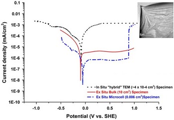
Figure 7 Potentiodynamic polarization curve of Type 304 SS in 0.001 M H2SO4. The black curve was measured using the in situ electrochemical cell with a 500 nm gap, blue curve was measured using the microcell, and the red curve was measured using the conventional bulk sample technique. a: Bright field transmission electron microscopy image shows the area imaged during the in situ electrochemical test.
Application to Austenitic Stainless Steels
As an exemplar of this validated experimental procedure, Figure 8, presents a series of hyperspectral images from a 0.03 wt% S Type 304 SS containing MnS inclusions prepared using all of the previously described protocols. The initial state of the region of interest is shown in the top row by bright field scanning transmission electron microscopy imaging as well as base-line Fe, Mn, and S elemental distributions. These initial state images were taken in the E-chip liquid holder, in 1 bar air (i.e., no liquid). Next, deionized H2O was introduced to the E-chip cell, the OCP conditions allowed to stabilize and the region of interest was then exposed to flowing liquid at room temperature with the electron beam blanked. The lower row documents the dissolution of the MnS inclusion, which was detected after 24 h in H2O.

Figure 8 Scanning transmission electron microscopy and scanning transmission electron microscopy--X-ray energy dispersive spectroscopy elemental images extracted from the hyperspectral data sets obtained from a hybrid specimen of 0.03 wt% S in 304 SS containing an MnS inclusion in electrochemical environmental cell. a–d: Initial state prior to introduction of H2O. e–h: After 24 h in flowing deionized H2O, illustrating the room temperature dissolution of the MnS inclusion.
MnS inclusions in low alloy steels and in austenitic stainless steels are associated with both localized corrosion/pitting, environmentally assisted cracking, and corrosion fatigue. Thus, this in situ result shows that even at room temperature, the inclusion dissolution process occurs.
The ability to microchemically assess and measure such ultrafine-scale localized reactions associated with the initial stages of dissolution/corrosion is important in developing an understanding of the precursor events for environmentally assisted degradation phenomena in engineering alloys, and, ultimately to aid in the development of predictive models for such materials degradation.
CONCLUSIONS
Using a modified E-chip electrode design and with careful control of instrument parameters, including the electron beam, and also employing hybrid specimen preparation procedure, we have validated a precise procedure for electrochemical studies of traditional metals and alloys during in situ TEM studies. Instances of contact corrosion due to non-optimized electrodes can be avoided as long as the cathode surfaces (more noble metal of the contact pair) are very small in relation to the anode surfaces (less noble metal of the contact pair). The evaluation of electron beam effects in distilled H2O and 0.001 M H2SO4 has shown that the conductivity of the electrolyte and its resistance depend on the charge transfer of the electrons in the incident beam and can be mitigated when carefully monitored. The in situ liquid cell potentiodynamic polarization curve of Type 304 SS in 0.001 M H2SO4 has been successfully measured in the TEM and comparison of conventional, microcell and in situ OCP data confirmed that the data generated using the hybrid specimen in the electrochemical E-chip cell were consistent with bulk behavior, although issues still remain in the measurement of current densities. Electrochemical behavior was also conclusively shown to be electron beam dependent and studies can be conducted in situ but only with careful monitoring and controlled conditions. Increasing the flow rate can reduce side effects such as pH, temperature differences and corrosion products, albeit with concomitant effects on image quality and resolution. Because of the influence of cell and electrode design, specimen geometry, electrolyte conductivity and flow rate, careful attention must be paid to experimental details during in situ TEM electrochemical in order that meaningful and accurate studies can be conducted.
Acknowledgments
The authors acknowledge the technical assistance of Dr J. Lindsay and X.L. Zhong of the Materials Performance Centre for assistance with FIB specimen preparation. The support from EPSRC PROMINENT programme (EP/1003290/1), Dr M.A. Kulzick and BP, is greatly appreciated. N.J.Z. also acknowledges partial support from the US DOE, Office of Science, Office of Basic Energy Sciences, under contract no. DE-AC02-06CH11357 in the Photon Science Division and the Electron Microscopy Center, in the Center for Nanoscale Materials, Nanoscience and Technology Division of ANL.


 Open access