


1. Introduction
Previous work has identified a series of thin-skinned growth basins with a very large footprint (Fig. 1) in Upper Triassic strata of Edgeøya in the eastern Svalbard archipelago (Edwards, Reference Edwards1976; Osmundsen et al. Reference Osmundsen, Braathen, Rød and Hynne2014). Associated fault zone deformation varies from being dominated by a soft-sediment style with particulate flow, hydroplastic folding and disaggregation bands, to brittle-style faults with fractured damage zones, breccias, coarse calcite veining and well-developed striae (Figs 2, 3). The top of a shale-dominated detachment zone with abundant shallowly dipping fault surfaces is well exposed in the cliff outcrops north of Kvalpynten (Fig. 1b). The associated diagenesis/lithification that drove the transition to brittle deformation is constrained to have occurred during faulting at a shallow level (<300 m before compaction).

Figure 1. Upper left: map of the Svalbard archipelago with inset box showing Edgeøya. Upper right: map of Edgeøya. The three ellipses are areas where Triassic growth basins occur (Snauheia, Blankodde and Kvalpynten, from north to south). Maps modified from Norsk Polarinstitutt's digital map site (http://toposvalbard.npolar.no/). Middle: photomosaic interpretation of two Kvalpynten growth basins (arrow on Edgeøya map shows the view direction). Red lines are bedding traces in sandstones, yellow lines are bedding traces in shale detachment zone and black lines are faults. Lower: the continuation of the middle panel to the right (NE).

Figure 2. Images documenting CIC and BF calcite mineralization field relationships. (a) Light-coloured CIC/BF mineralization overprinting a soft-sediment fault (white arrows) with a hanging-wall flat and footwall cut-off. The lighter band along the fault is CIC/BF mineralization. Rifle case (lower right) for scale. (b) Field photo of finely branching and complex CIC aggregates defining fault subparallel fracture features. Image contrast was increased to highlight aggregates. White arrows: two surfaces linking fault-parallel calcite aggregates with CIC and BF fabric evident in thin-sections. Camera lens cap (lower left) for scale. (c) CIC/BF subhorizontal aggregates (unassociated with a fault zone) conformable to bedding and fissility. Note linking tip curls in the area outlined with a dashed ellipse. (d) Image of folded and bedding-parallel fibrous calcite vein (BF) in black shales. Note the shale fissility is also folded.

Figure 3. Images documenting the field relationships of the late brittle phase of faulting. (a) Field photograph of low-angle normal fault zone. Movement of top part towards left. 1 – hanging-wall sandstone bed; 2 – zones of concentrated brittle slip surfaces; 3 – coarse subvertical calcite vein in a relay position between slip surfaces; 4 – relay slip surface between dilational veins; 5 – more uncommon coarser phase of CIC/BF development with cone axes subperpendicular to slip surfaces; 6 – more typical, orange-weathering, finely branching, subhorizontal CIC aggregates. Upper inset: soft-sediment faulting in sandstone layer, but just out of view. Lower inset: close-up of coarser CIC. (b) Photo of coarse calcite vein along low-angle brittle slip surface, with low-angle cut-off of bedding and fissility in the hanging wall and a footwall flat. Banding in the calcite vein reflects internal subvertical microvein array with bounding slip surfaces. The thin-section sample shown in Figure 8 was collected here.
Subhorizontal and finely feathered veins filled with cone-in-cone (CIC) structures and fibrous calcite veins (commonly known as beef or BF) that are typically bedding-parallel are fairly common in Upper Triassic strata of eastern Svalbard, with a greater abundance in the Tschermakfjellet Formation shales and with occurrences in the overlying De Geerdalen Formation sandstones (Tugarova & Fedyaevsky, Reference Tugarova and Fedyaevsky2014). CIC and BF also locally ornament fault surfaces in the growth-basin detachment zone. Based on the unusual association of CIC and BF directly with fault structures of Kvalpynten, this paper documents field relations and thin-section textures of this carbonate mineralization from the Kvalpynten area (Fig. 1), explores how the mineralization tracks a transition from a hydroplastic to brittle-deformation-fault-zone style, and considers how they may inform an understanding of the interplay between diagenesis and changing growth-basin faulting mechanics.
2. Background to cone-in-cone structures
CIC structures are distinctive fibrous mineral growths displaying a nested cone geometry. They are typically composed of calcite, occur in organic-rich shales and form bedding-parallel lenticular aggregates (Pettijohn, Reference Pettijohn1975). However, variants occur such as celestite instead of calcite (Ábalos & Elorza, Reference Ábalos and Elorza2011) and concretions hosted in sandstone instead of organic-rich shales (McBride, Picard & Millikin, Reference McBride, Picard and Millikin2003). CIC often occur together with BF (Cobbold & Rodrigues, Reference Cobbold and Rodrigues2007), both of which may influence shale reservoir hydrocarbon production (Gale et al. Reference Gale, Laubach, Olson, Eichubl and Fall2014).
CIC are somewhat enigmatic; they have been of interest since the 1800s (e.g. Gresley, Reference Gresley1887) and hypotheses for their generation range from seismic-wave-related fracture systems (Ábalos & Elorza, Reference Ábalos and Elorza2011) to compaction- and dewatering-related displacive calcite growths associated with initial high overpressures (e.g. Franks, Reference Franks1969; Sellés-Martinez, Reference Sellés-Martínez1994). McBride, Picard & Millikin (Reference McBride, Picard and Millikin2003) provide a succinct review of CIC growth models. Whether the cone geometries reflect a fracture pattern control on mineral growth, a later superimposed fracture pattern (e.g. Sellés-Martinez, Reference Sellés-Martínez1994) or simply a distinctive displacive calcite growth geometry under shallow burial conditions is debated. This may be because as a broader group CIC morphology is polygenetic. The strong association with organic-rich mudstones supports the contention that microbial processes play a role in shale-hosted examples (see discussion in McBride, Picard & Millikin, Reference McBride, Picard and Millikin2003).
Of significance to this report is the recent work that suggests that CIC and BF are related to seepage forces (Cobbold & Rodrigues, Reference Cobbold and Rodrigues2007). Seepage forces result from the influence of the fluid flow on the solid sediment framework it passes through, and are associated with pore pressure gradients associated with the boundaries of over-pressurized zones. Cobbold & Rodrigues (Reference Cobbold and Rodrigues2007) explore how horizontal tensile fractures are mechanically enigmatic in a simple lithostatic stress field where vertical fractures are to be expected, but can be explained by considering how vertical seepage driven by pore-water-pressure gradients would influence fracture dynamics. They apply the concept of seepage forces to help explain thin-skinned deformational features seen in the Niger Delta (Cobbold, Clark & Løseth, Reference Cobbold, Clark and Løseth2009), and have also replicated similar subhorizontal tensile fractures experimentally (Mourgues & Cobbold, Reference Mourgues and Cobbold2003; Cobbold, Durand & Mourgues, Reference Cobbold, Durand and Mourgues2010).
3. Field relationships of carbonate mineralization at Edgeøya
Growth basins within the Triassic sedimentary succession of Edgøya, first described by Edwards (Reference Edwards1976), are known from three different localities on Edgeøya (Rød, Hynne & Mørk, Reference Rød, Hynne and Mørk2014; Osmundsen et al. Reference Osmundsen, Braathen, Rød and Hynne2014) which are (from north to south): Snauheia, Blanknuten and Kvalpynten (Fig. 1). Basin fill includes strata of both the Tschermakfjellet and De Geerdalen formations, as these units are presently defined, but basin faults are truncated within the De Geerdalen Formation. Both formations are of Carnian age (Lundschien, Høy & Mørk, Reference Lundschien, Høy and Mørk2014). The mudstone-dominated Tschermakfjellet Formation is broadly interpreted to record a pro-delta setting, while the De Geerdalen Formation is interpreted as a delta top (Riis et al. Reference Riis, Lundschein, Høy, Mørk and Mørk2008). At both Snauheia and Blanknuten it is clear that the growth basins sole above or partly at the top of the underlying Botneheia Formation, of Anisian–Ladinian age, which consists primarily of organic- and phosphate-rich marine shales. The Botneheia Formation was subject to shallow diagenetic carbonate and phosphate cementation (Mørk, Knarud & Worsley, Reference Mørk, Knarud, Worsley, Embry and Balkwill1982; Krajewski, Reference Krajewski2008), which may have played a role in localizing the overlying detachment. At Kvalpynten, the source of samples and observations discussed in this article, the upper part of a complex detachment zone is well exposed in cliff outcrops of the Tschermakfjellet Formation (Fig. 1b); the very base of the detachment and underlying Botneheia Formation strata are inferred to be just below sea level. Edwards (Reference Edwards1976) attributed the growth basins to delta front collapse, but there has been debate as to how these may be related to steeper faults of the same orientation in the area and whether there is a tectonic influence (Anell et al. Reference Anell, Braathen, Olaussen and Osmundsen2013; Osmundsen et al. Reference Osmundsen, Braathen, Rød and Hynne2014).
The CIC and BF in the detachment horizon mudstones occur both as (1) isolated and bedding-parallel lenses with no apparent association with the fault structures and (2) as lenses and aggregates clearly associated with some of the faults (Figs 2, 3). They also occur in equivalent strata in areas where the growth basins do not exist (Tugarova & Fedyaevsky, Reference Tugarova and Fedyaevsky2014). The lenses, typically metres long and centimetres to several tens of centimetres thick, consist of subhorizontal and/or fault-parallel aggregates with tapered ends, composed internally of a fine and complex branching network of wispy, smaller calcite vein material (Fig. 2). Weathering of the calcite to a light orange colour enhances the contrast between the carbonate mineralization and host rock, and in fresh faces the distinction is much harder to see. Geometries seen are consistent with these lenses being tensile propagating fractures (Fig. 2), although thin-sections suggest they are veins of a distinctive character (discussed in Section 6.c). Typically the grain size is fine, making it difficult to determime the internal CIC and BF organization at outcrop or hand specimen scale, but coarser and visible instances occur (Fig. 3a).
The authigenic calcite occurs both along hydroplastic faults without a brittle overprint and along faults with a mixed hydroplastic and brittle history. In the former, undeformed CIC/BF growth extends from the fault zone into the footwall and hanging wall, clearly indicating that calcite growth nucleated along and overprinted a pre-existing fault surface (Fig. 2). Lenses of the CIC/BF mineralization along bedding were also observed to be preferentially developed adjacent to the fault, tapering away from it. In several localities the calcite veins are folded in association with detachment zone deformation (Fig. 3). Along low-angle detachment zones with a brittle component, the finer-grained CIC/BF growths are locally cut by coarser, milky-white, calcite veins associated with the brittle phase (Fig. 3) and by brittle slip surfaces. These field relationships firmly place carbonate mineralization as during the faulting and, more specifically, during the transition from hydroplastic to a more brittle structural style.
A distinctive geometry of vein aggregate is seen in the immediate footwall of faults where smaller subhorizontal CIC micro-veins branch from a linking and medial thin surface that is at a high angle to the fault surface and/or bedding (Fig. 2). The linking surface is often fairly short, typically 20 cm or less. In many cases the subhorizontal branches curve upwards. Thin-sections of this branching geometry are described in Section 4.b and provide some constraints on models for CIC/BF formation.
Later brittle fault surfaces are typically characterized by discontinuous shale membranes (fault-parallel thin layers of shale gouge and protobreccia to ultrabreccia; membrane as described in Braathen et al. Reference Braathen, Tveranger, Fossen, Skar, Cardozo, Semshaug, Bastesen and Sverdrup2009) representing the fault core, bounded by striated, and sometimes polished, discrete slip surfaces. Coarse calcite mineralization also occurs along dilational jogs of the late-stage brittle detachment surfaces (Fig. 3) forming fault-surface-parallel lenses, where the upper and lower bounds are typically striated or finely corrugated slip surfaces. A closer look shows they are internally composed of steeply dipping vein arrays with the vein walls at a high angle to the enclosing slip surfaces. These arrays are interpreted as hard linkage of corrugated slip surfaces by tensile openings. The significance of their orientation relative to the slip surfaces is discussed in Section 6.f. The coarse calcite can be seen to cross-cut and replace the CIC and BF mineralization in the fault zones that record a ductile to brittle transition (Fig. 3a). Given the lack of any evidence of significant erosional surfaces between the growth basin fill and the overlying De Geerdalen Formation strata, and undoing compaction, this ductile to brittle transition occurred at a depth of <300 m.
4. Description of CIC/BF in thin-section
The repeated basic architectural element that comprises the CIC aggregates is referred to as an individual cone element (ICE), defined by a conical wall, internal fibrous calcite crystals and a blunt-end termination (Fig. 4). Typical ICE wall, fill and termination characteristics are described in the following section, followed by a description of the distinctive geometries ICE elements combine to create CIC/BF aggregates (Section 4.b) and of their relationship to fault zone deformation (Section 4.c).

Figure 4. Figures showing microscopic character of ICE. (a) Photomicrograph mosaic from sample 12ED15 with crossed polars and gypsum plate (reducing contrast to produce better images for texture documentation). Image is oriented so that up is up. 1 – V-shaped inclusion and wall trace of a nested cone element; 2 – stepped, upper terminations of calcite fibres against host sediment traces; 3 – framboidal pyrite within ICE; 4 – quartz grains at cone apex; 5 – cone walls that can be traced to the inner portion of a step. (b) Photomicrograph mosaic from sample 12ED20, with crossed polars and gypsum plate. 1 – relatively constant thickness calcite fibres; 2 – inter-calcite silty-muddy sediment with variable degree and orientation of preferred orientation of grains; 3 – ICE that combine to make funnel aggregates; 4 – stepped margin of calcite fibre growth. (c) Tubular and branching fluid inclusions from sample 1AB12. (d) Schematic diagram of the basic building block of the cone-in-cone aggregates: an individual cone element (ICE).
4.a. ICE walls, interior and terminations
Conical ICE walls are defined by entrained sediment of varying thickness, a concentration of fluid and/or solid inclusions, or a mix of the two. Entrained sediment grains defining an ICE wall can thin and grade into a concentration of inclusions within the calcite either from the upper margin downwards or from the apex upwards (e.g. Fig. 4). Inequant grains in the wall sediment between ICEs often show a high degree of preferred orientation parallel to cone walls (Fig. 4b). Apical angles of the cones have potential mechanical significance if interpreted as shear fractures. When measuring apical angles, the cone orientation relative to the thin-section plane is an important consideration. Curved profiles most likely represent off-axis cuts, while those with straight walls that come to a sharp point likely pass through the apex. Thin-sections were cut so that the cone axis should be in the thin-section plane; while curved boundaries are seen, cone walls of a geometry indicating that the thin-section plane contains the cone axis, are easily found. Measurements of such cone cross-sections in thin-section yield apical angles that vary significantly over the range 25–60°.
Cones can be asymmetrically developed, especially inside the CIC aggregates, which can be interpreted as composed of a mosaic of more fully formed ICE with truncated, partial ICE between them. In some cases quartz grains are preferentially located at a grain apex (Fig. 4a); in other cases cone apexes are located along the top of a larger ICE, forming stacked or nested cone arrays. In most thin-section areas there is a strong directionality where the better-defined and larger cones open upwards, although some show asymmetric bi-directionality on either side of an interior planar surface (discussed in Section 6.d).
The ICE interior consists of calcite fibres with a strong crystallographic preferred orientation (Fig. 4), as indicated by a common maximum polar-parallel extinction. Fibres have either tapered termini internally (potentially a function of thin-section cut) or end in stepped boundaries against host sediment (Fig. 4a, b), and vary in thickness over the range 0.01–0.05 mm. Significantly, the extinction direction does not radiate within the cone but instead is oblique to the cone walls.
The CIC calcite includes abundant fluid inclusions not only defining the ICE walls, but throughout the interior (Fig. 4c). Many are elongate and are concentrated along cleavage planes but there is also a distinctive tubular morphology with a relatively constant width, forming branched and locally curved three-dimensional (3D) networks. The potential significance of these is discussed in Section 6.e. The fluid inclusion array in later coarse-grained calcite is mostly of a distinctly different morphology typically influenced by the cleavage geometry, although a few tubular fluid inclusions were also found in this material.
Upper ICE terminations into host sediment can be slightly concave upwards (Fig. 5), akin to a 3D botryoidal texture seen in aggregates of ICE. The well-defined and stacked annular rings of sediment evident along the walls of many CIC structures elsewhere (e.g. http://serc.carleton.edu/NAGTWorkshops/sedimentary/images/cone.html; Pettijohn, Reference Pettijohn1975) are typically not readily evident at hand-specimen scale at Kvalpynten. However, an equivalent feature is evident in thin-section where adjacent crystal fibres at the blunt end of the cone element and along its margin terminate in a stepped manner (Fig. 4a, b). In 3D the sediment trapped between the stepped margin and the wall of the adjacent cone forms rings of darker material around the stacked ICEs, representing the microscopic equivalent of annular rings seen elsewhere. Commonly ICE-internal inclusion traces defining interior ICE walls can be traced to the inside corner of these steps. The significance of this geometry is discussed in Section 6.b. The angles between the steps are consistent with rhombohedral cleavage/growth faces.

Figure 5. Photomicrograph mosaics showing character of CIC aggregates. (a) Two sheet ‘fractures’ of CIC aggregates (sample 12ED16A), plain light. Up is stratigraphically up. 1 – curved, but smooth and well-defined nucleation surface defined by a medial concentration of fluid inclusions and adjacent finer-grained and variably oriented calcite; 2 – irregular upper margin defined by nested CIC florets with concave-upwards sediment contact; 3 – cone walls/septa defined by sediment grain traces that can be traced up to upper crack margin; 4 – small cones that open downwards on the ‘underside’ of the fracture. (b) Same sample as in (a), plain light. Vein tip partially ornamented by fibrous calcite. Arrows mark a medial suture zone with concentrated fluid and opaque conclusions. 1 – calcite fibres oblique to the nucleation fracture and with an stepped upper boundary; 2 – position on vein left of which fibrous calcite growth is absent (calcite fibre fringe tapers in same direction as the vein tapers); 3 – framboidal pyrite. (c) Mosaic from sample 12ED20, with crossed polars and gypsum plate. 1 – fossil platelet on which CIC growth nucleated; 2 – mixed BF and CIC aggregates; 3 – tip of fracture that grew past nucleating platelet. (d) Photomicrograph mosaic (sample 12ED16A) with branching structure, plain light. 1 – steeply dipping fracture surface characterized by smaller grain size and concentrated fluid and solid inclusions; 2 – framboidal pyrite along a soft-sediment deformation fabric; 3 – proximal CIC axes roughly 45° to 1; 4 – more distal reoriented and upwards-directed CIC aggregate, similar to bedding-parallel fracture aggregates in (a). (e) Photomicrograph mosaic (12ED12), with crossed polars and gypsum plate. 1 – medial surface defined by smaller grain size and concentration of inclusions; 2 – funnel CIC aggregate with trumpet-like geometry; 3 – asymmetric tapered fracture as seen in (a), following shear zone fabric.
4.b. Aggregate CIC and BF geometries
As in outcrop, the aggregates of CIC and BF in thin-section most often define tapered features easily interpreted as tensile fractures (Fig. 5a); they can also define more complicated masses however, including semi-isolated flaring cone geometries (Fig. 5e). Taper angles at aggregate tips vary significantly from relatively blunt to finely tapered (Fig. 5b). ICE or BF fibres are typically asymmetrically perpendicularly disposed on either side of fossil calcite platelets or, more commonly, a planar thin zone defined by a concentration of inclusions and fine-grained and non-fibrous calcite without a crystallographic preferred orientation (Fig. 5). Using the terminology of Anders, Lubach & Scholz (Reference Anders, Lubach and Scholz2014), the latter features are interpreted as sealed tensile microfractures. These are typically bedding or fault-plane parallel although, in some cases, linking versions that are highly oblique to bedding-perpendicular occur, forming a distinctive branching pattern (Fig. 5d, e). These nucleation surfaces are typically found near the lower boundary of an individual CIC aggregate, with a greater thickness of ICE and BF above than below.
The upper aggregate boundary with the host sediment is typically more irregular and marked by hemispherical florets of CIC (e.g. Fig. 5a) in a geometry that is interpreted as a frozen growth/crystallization front. Entrained sediment within CIC aggregates can often be traced to the boundary of a floret at the upper, more irregular margin (e.g. Fig. 5 a, d, e). Often simple parallel fibres (BF) directly adorn a nucleation surface and then change into ICE morphology further away, suggesting a tendency to evolve towards the CIC morphology with continued development. However, ICE morphology sometimes occurs within otherwise fibrous portions (Fig. 6a), indicating an overlap in time of growth of the two forms. Figure 5b shows the tip of one of the tensile nucleation fractures, with BF/CIC systematically increasing in thickness along the length of the feature away from the tip.

Figure 6. Photomicrograph mosaics of CIC soft-sediment shear zone relationships. (a) Mosaic of sample 12ED20 with crossed polars and gypsum plate. Upper portion: mixed ductile-brittle shear zone with top to left movement (section oriented parallel to movement direction). 1 – median zone with flanking mixed CIC/BF calcite aggregates; 2 – distinct anticlockwise bending of CIC/BF axes; 3 – tapered ends of asymmetric CIC funnel aggregates; 4 – shear zone with oblique fine-grained calcite microveins in host sediment; 5 – small tension gash of coarser, equant calcite. (b) Same sample as (a). Several calcite sealed microfractures in the sediment with enveloping surfaces subparallel to shear zone walls with geometry consistent with top-left movement. (c) Mosaic of sample 12ED15 with crossed polars and gypsum plate. 1 – sinistral soft sediment shear zone; 2 – nucleation surface with asymmetric CIC/BF development; 3 – flaring CIC aggregates with tips that grew into the shear zone; 4 – CIC/BF aggregate that cuts shear zone; 5 – typical upper growth front of CIC aggregate.
One particularly distinctive aggregate geometry comprises branching, almost tree-like, CIC aggregates (Fig. 5d, e). The medial steeply dipping nucleation surface is adorned by ICE axes disposed obliquely (at about 45°) to either side of the medial surface (also helping to define the asymmetry). As stacked ICE are traced outwards, the axis reorients towards a more subvertical position in fault-plane-parallel tapering aggregates. These distinctive branching forms establish that at thin-section scale the ICE and crystallographic axes preferred orientation can vary significantly, although systematically. Larger, relatively isolated, cone aggregates also exist (Fig. 5). Some of these flare outwards significantly so that the cone margin is strongly curved in cross-section and the upper tips taper at a very low angle (Fig. 6). Typically they open upwards, and indicate that CIC floret-like aggregates can initiate independently of a tapered fracture setting.
4.c. Hydroplastic to brittle deformation transition and CIC development
Sediment entrained within the CIC aggregates consistently shows a fabric that conforms to cone walls (e.g. Fig. 4). The degree of fabric development is a function of the thickness of the sediment trapped between the calcite growths so that, as a thinning wedge of sediment is traced into the aggregate, the fabric becomes better developed. This geometry is consistent with displacive growth moulding unconsolidated sediment. In thin-section samples collected from fault zones, undeformed CIC aggregates also clearly grow into hydroplastic shear zones (e.g. Fig. 6) and therefore post-date deformation; this timing is consistent with observed field relationships. Figure 6a shows a CIC/BF aggregate adjacent to a soft-sediment shear zone where several attributes indicate development during fault-related deformation. With reducing distance to a micro-shear zone, fibre and cone axes bend in a manner consistent with the sense of shear. Small oblique microveins in the micro-shear zone show a complex mix of internal fibre development, demonstrating finer-grained and more equant calcite, and en échelon, tension gash pods of coarser, equant calcite consistent with the sense of shear (Fig. 6a, b). Coarser calcite is associated with the latter brittle phase of faulting (Fig. 3), and the textures in this thin-section (Fig. 7) are interpreted as capturing the transition from a hydroplastic to brittle style.

Figure 7. Photomicrograph mosaic of conjugate calcite deformation twins from Figure 6a (2), with crossed Nicols (without gypsum plate). 1 – traces of adjacent and thin deformation twin planes close to 52°; 2 – stylolite seam; 3 – area of neocrystallization.
Calcite deformation twins are well developed in deformed CIC fibres in the mixed brittle-ductile shear zone (Fig. 7). The twins are very thin and appear to form in two sets, which could be interpreted as a conjugate set. Twins that are oblique to the thin-section appear thicker and interference colours can be seen along them, while those close to perpendicular to the thin-section appear as ruler-like lines due to the along-plane perspective. Since calcite twins are controlled by the lattice structure a conjugate angle is constrained at 52° (Lacombe, Reference Lacombe2010), which sigma-one (maximum principal stress) should bisect in a simple situation. In areas where the twins appear thin, indicating an along-plane perspective, the angle between them is within a few degrees of the expected 52° (Fig. 7a) and other angles are close to this. Given this, qualitatively it appears that the bisector of the smaller conjugate angle is at a high angle to the fibre axis and roughly in the plane of the thin-section. Given the orientation of the thin-section, the resulting sigma-one would be at a very low angle to the fault plane and roughly in the direction of slip.
Some stylolite seams are also evident, clearly truncating the fibrous texture at an overall low angle. The seam orientation and relief are consistent with pressure solution induced by a sigma-one at a high angle to the fibres and at a low angle to the fault plane. Moderate undulose extinction is also associated with the twins, as are some fine-grained neo-crystallization mantling large grains (Fig. 7).
5. Description of coarser calcite mineralization in thin-section
In thin-section, the coarser calcite vein material is composed of microvein arrays at a high angle to bounding slip surfaces and micro-shear zones (Fig. 8a), consistent with outcrop-scale observations. With some microveins truncated by slip surfaces and others cutting through slip surfaces, the microveining and brittle slip are coeval. Individual quartz grains were extended in a brittle manner within the micro-shear zones in a micro-boudinage geometry, but show no internal undulose extinction (Fig. 8b). More diffuse, thinner and finer-grained calcite aggregates, interpreted as earlier subhorizontal veins, are clearly cut by these coarser veins.

Figure 8. Photomicrograph mosaics showing character of coarse, blocky calcite within brittle fault zone (sample 12ED08), oriented parallel to striae and perpendicular to the fault plane. Image with crossed polars and gypsum plate. (a) 1 – later truncating brittle slip surface; 2 – earlier brittle slip surface that truncates some veins but is cut by others; 3 – relay calcite microveins that link movement from one slip surface to another; 4 – calcite grains with a long axis perpendicular to the vein direction, and parallel to the movement direction; 5 – fluid inclusion planes subparallel to 3 that transgress multiple grains; 6 – calcite deformation twins; 7 – finer-grained band of calcite parallel to the slip surfaces that pre-dates 3. (b) Mosaic of brittle pull-apart of quartz grain (labelled as 1) in micro-shear zone; 2 – upper boundary of micro-shear zone. (c) Small planar arrays of fluid and solid inclusions that transgress calcite grains.
Within microveins calcite crystals do not show an obvious crystallographic preferred orientation, but grain cross-section shapes are typically longer subperpendicular to the microvein walls and subparallel to the slip direction (Fig. 8a), forming an ‘elongate blocky’ texture (Lander & Laubach, Reference Lander and Laubach2015). Grain boundary walls are often planar, although a few serrated subhorizontal contacts suggest occurrence of limited pressure solution. Internal grain size is a direct function of vein width. Deformation twins also occur within the calcite, although undulose extinction was not observed. The deformation twins do not show the systematic conjugate geometry similar to that evident in the fibrous calcite. Planar arrays of solid and fluid inclusions subparallel to and within the microveins are common (Fig. 8c). The fluid-inclusion planes (FIPs) are considered to be microfractures that have formed during microvein development and fault slip.
6. Discussion
The discussion is based on several questions considered of interest in understanding the formation of CIC and the interplay between carbonate mineralization, diagenesis and deformation.
6.a. Are ICE walls shear surfaces?
The conical surfaces in CIC elsewhere have been considered to be shear fractures (e.g. Ábolos & Elorza Reference Ábalos and Elorza2011; Cobbold & Rodrigues, Reference Cobbold and Rodrigues2007). In this case sigma-one would be oriented parallel to the cone axis and, given that most of the axes are subvertical, this would make sense in a simple lithostatic field without a significant tectonic component. However, the CIC are attached to and are infill of subhorizontal tensile fractures, where ostensibly sigma-three (minimum principal stress) would be vertical (discussed in Sections 6.d and 6.f). Calcite fibres also preferentially grow in the sigma-three direction. Cobbold & Rodrigues (Reference Cobbold and Rodrigues2007) address the enigma of how subhorizontal fractures with internal subvertical fibres could form without a compressive tectonic stress component (unlikely in the case of Edgeøya given the normal faulting regime; Osmundsen et al. Reference Osmundsen, Braathen, Rød and Hynne2014). They attribute this morphology to vertical seepage forces which, if strong enough and especially at a shallow depth, could overcome the vertical lithostatic component.
Simultaneous subhorizontal fracture growth and development of cones as a shear fracture geometry is incompatible if the cone axis defines the sigma-one direction. For CIC in general Sellés-Martínez (Reference Sellés-Martínez1994) address this incompatibility with a two-stage history of initial calcite growth and later overprinting of the shear surfaces, once transient high pore pressures are relieved and compaction and lithostatic forces dominate. However, for the Edgeøya samples this leaves unexplained the sediment entrained between the cone elements, the isolated cone aggregates enclosed in sediment, the irregular upper growth front and preferred asymmetry of the aggregates, and the varying cone orientation seen in the branching aggregates. The significant variation in apical angles and implied steep angles for the Mohr envelope for low apical angles also complicate an interpretation of the cones as shear fractures. For these reasons, the ICE walls are not considered to be shear surfaces.
6.b. How can ICE walls form from fibrous growth dynamics?
The stepped edges of the upper bound of ICE (e.g. Fig. 4a) appear key to the formation of conical ICE walls defined by inclusions and/or entrained sediment. The steps are often non-orthogonal and are interpreted to represent calcite growth faces parallel to cleavage. If growth of these faces is differential in rate due to their orientation relative to the local stress field and/or fluid flow directions (e.g. faster growth in the sigma-three direction), then the result will be that the successive inside corners of the step will follow a trajectory oblique to that of the preferred growth direction. If fluid and sediment inclusions are preferentially trapped at the internal corners in the wake of growth, the result will be conical ‘walls’. In many cases the cone wall can be traced to an inner corner of a stepped margin, supporting this hypothesis (Figs 4a, 5a). The apical angle would then be a function of the relative differential growth rates of the two faces, and this would explain the variability of apical angles seen. New steps could be created along the growth front as any given fibre grows ahead of adjacent fibres, initiating the development of new inclusion incorporation sites and therefore cone walls. By repeating this process over time along an irregular growth front composed of newly nucleating and competing cones, the great diversity and complexity of specific CIC structures can be created.
An important question to consider is the reason the growth is preferential at one end. One explanation would be the inability of the previously formed calcite to be displaced, preventing crystal fibre growth in this direction; growth is therefore antitaxial on the outer margin where sediment can be displaced and pore water provides ions necessary for growth. The development of the fabric in the sediment conforming to the walls of individual CIC structures and CIC aggregates is explained by displacive growth of the calcite as the sediments become squeezed out from between growing elements. This implies that the sediment was still plastic and unlithified during CIC formation, consistent with literature that describes CIC as forming early in diagenesis (e.g. McBride, Picard & Millikin, Reference McBride, Picard and Millikin2003). BF and CIC are intergrown in a manner that indicates they overlap in time, although typically BF are more proximal to the nucleation surface and interpreted to have formed earlier (e.g. Fig. 6a), and CIC are more distal and interpreted to have developed later (Figs 5, 6a). This may be due to the amplification of small initial irregularities in the BF growing front.
However, the numerous examples of asymmetric growth on either side of a nucleation surface, typically greater upwards, need explanation. A non-hydrostatic stress state can easily explain the preferred orientation by controlling growth rates of differently oriented faces, but the reason for the preferred upward growth direction may lie in the shallow burial setting, the direction of fluid flow, the associated seepage forces and the greater ease of displacing unlithified sediment upwards versus attempting to displace a larger and more rigid CIC aggregate upwards.
6.c. Displacive crystal growth versus tensile fracture fill
In outcrop and thin-section the CIC/BF aggregates appear as finely feathered, anastomosing tensile fractures. It is clear that wedges of aggregates are not replacive but displacive, given the way the fabric in the host sediment is influenced. The observation of relatively isolated cone components indicates that a tensile failure opening is not needed for CIC formation, as does the way in which they adorn shell fragments (although shells fragments could nucleate microfractures). Consistent thickening of CIC/BF adornment away from tips (e.g. Fig. 5b) is consistent with concurrent tip propagation and CIC/BF growth, with the younger tip having had less time to accumulate CIC/BF. It is conceivable that thin tensile calcite veins initiated subsequent CIC/BF displacive growth. It is also conceivable that the width of the aggregate is not a function of passive infilling of a widening fracture driven by the stress state, but simply of the amount of crystal growth and associated sediment displacement. In such cases, forces associated with directed displacive crystallization may have contributed to the continued propagation of irregular fracture tips (Wiltschko & Morse, Reference Wiltschko and Morse2001).
Some of the sheet fractures have tip curls (Fig. 2c), a propagation geometry of tensile fractures associated with low deviatoric stresses (Olson & Pollard, Reference Olson and Pollard1989), consistent with the shallow formation depth. At present it is not clear to us how to separate the relative roles of fault-related fracture infilling versus shallow displacive crystal growth in CIC/BF aggregate development. The common occurrence of the CIC/BF aggregates in unfaulted Triassic strata of Edgeøya indicates that fault-related loading is not a prerequisite for their formation. In either case, it is reasonable to assume that sigma-three was locally perpendicular to the fracture aggregate and parallel to ICE axes. Distinctively, these veins can be considered as asymmetrically antitaxial, growing preferentially on the outer and upper surface.
6.d. Why is there a general preferred orientation/direction of calcite fibre growth?
The strong preferred calcite crystallographic orientation in a bedding- or fault-perpendicular orientation warrants further explanation. The three possibilities considered are: (1) oriented crystal growth within a stress field, ostensibly in the sigma-three opening direction; (2) alignment with a fluid flow direction; and (3) an inherited and continued growth direction perpendicular to a nucleating surface. These are considered in succession in the following, with the branching CIC aggregates providing important insight.
Calcite fibres tracking the tensile fracture opening direction are well known and described (e.g. Hilgers & Urai, Reference Hilgers and Urai2005). Combined with theoretical considerations, this suggests preferred growth in a steeply oriented sigma-three direction. The common subhorizontal tensile fractures that the CIC nucleate on and occur within (with tip-curl geometries) are consistent with a subvertical sigma-three. However, this is broadly inconsistent with a stress regime that would produce the concurrent normal growth faulting or the stress regime associated with a simple lithostatic gradient. This is the quandary mentioned in Section 6.a that Cobbold & Rodrigues (Reference Cobbold and Rodrigues2007) solve by considering seepage forces driven by overpressure gradients. In this case the direction of fluid flow locally influences the stresses, and both could contribute to a preferred orientation of calcite growth. Compaction-related fluid flow would be expected to be generally upwards, but faulting-related hydraulic head gradients and fluid flow could be fault perpendicular or in other directions. Pipey concretions are interpreted to be aligned with groundwater flow directions, including preferential pathways along shallow faults (Mozley & Goodwin, Reference Mozley and Goodwin1995; Balsamo, Storti & Gröcke, Reference Balsamo, Storti and Gröcke2012), and demonstrate the ability of fluid flow to control the direction of diagenetic carbonate growth in general. The mechanism is unclear, but could involve differing solute concentrations along faces at various orientations to the flow direction.
The branching geometry seen in the Edgeøya samples, where there is significant and systematic variation in fibre and cone orientation (up to 45° difference) on a thin-section scale (Fig. 5c, d), is potentially instructive. How could stress and/or fluid flow result from this growth/propagation geometry? One possibility may lie in the interplay between seepage forces due to fluid flow (both fracture and intergranular) and the larger ambient stress field. If a subvertical fracture locally served as a fluid conduit then, as it leaked into the adjacent porous sediment and responded to a steeply oriented pressure gradient decreasing upwards, either side of the fracture would experience oblique fluid flow. Accordingly, reorientation of stresses may result. With distance from the subvertical fracture the flow and seepage forces would return to background levels and orientations dominated by intergranular flow, causing the cones and propagation direction to reorient. The mixture of differently oriented but linked fractures may reflect a stress state and mechanics sensitive to small changes (discussed in Section 6.f).
Two observations contradict the third hypothesis of simple perpendicular growth to a nucleating surface. First, cases where the fibres and cones are significantly oblique to the nucleating shell fragment occur. Second, the alignment of more isolated cone aggregates with the general preferred direction could not be explained in this way, since they nucleate from a single point (e.g. Fig. 5e) and not a surface.
6.e. Is there biogenic influence?
The occurrence of branching tubular fluid inclusions in CIC growing in organic-rich sediment raises the possibility of a biogenic factor (e.g. Buijs et al. Reference Buijs, Goldstein, Hasiotis and Roberts2004; McLoughlin et al. Reference McLoughlin, Brasier, Wacey, Green and Perry2007). These structures have a fairly consistent width of c. 0.5–1 μm (Fig. 4c). This is less than that of endolithic borings in shells (5–8 μm in diameter), but is similar to the diameter of many bacteria and within the range of nanobacterial borings (McLoughlin et al. Reference McLoughlin, Brasier, Wacey, Green and Perry2007). However, this is also a common scale of inorganic fluid inclusions. Bons et al. (Reference Bons, Montenari, Hartmann and Elburg2004) describe microbial traces in Precambrian fibrous calcite veins that formed at a depth of 4–6 km, significantly greater than that proposed here.
Tugarova & Fedyaevsky (Reference Tugarova and Fedyaevsky2014) describe an assemblage of carbonate bodies on Edgeøya, mostly within the Tschermakfjellet Formation, that they attribute to sediment-surface or near-surface biogenic processes. This includes a later stage of CIC ‘fouling’ or overgrowth on microbial carbonate mats. They attribute the CIC to ‘biochemical precipitation of calcite (or aragonite), which is controlled by the presence of bicarbonate in the sediment environment and biological factors – liming and extraction of carbon dioxide during photosynthesis’ (Tugarova & Fedyaevsky, Reference Tugarova and Fedyaevsky2014; p. 151). In the Kvalpynten area, the ability to trace the CIC along discordant-to-bedding fault surfaces clearly indicates that CIC growth occurred at burial depths of at least tens of metres.
McBride, Picard & Millikin (Reference McBride, Picard and Millikin2003) describe large concretions in Cretaceous sandstones in the US with internal CIC textures. They speculate that biogenic processes were involved and that concretion growth occurred at sediment depths of no more than tens of metres. They also note that deeper methanogenic activity utilizes carbon dioxide in the pore water and could produce carbonate supersaturation. Tugarova & Fedyaevsky (Reference Tugarova and Fedyaevsky2014) provide some isotope data, with four samples from the CIC collected on Edgeøya. These samples have only slightly negative carbon values, which is inconsistent with formation during methanogenesis. The abundant framboidal pyrite found in the Edgeøya samples suggests significant biogenic sulphate reduction. Borowski, Paull & Ussler (Reference Borowoski, Paull and Ussler1999) document that the sulphate to methane transition in modern marine sediments occurs at depths below sea bottom of up to 200 m and is partly a function of water depth, sedimentation rate and the presence or not of any upwards-directed methane flux. Depending on the metabolic path, microbial sulphate reduction can increase the calcite saturation index (Gallagher et al. Reference Gallagher, Dupraz and Visscher2014). The authigenic calcite that ornaments the Edgeøya faults could be related to biogenic sulphate production and sulphate depletion at depths of tens of metres or more. The systematic occurrence of pyrite-impregnated portions of samples collected within sheared/smeared sediment in the fault cores further testifies to a linkage between deformation, fluid flow pathways and diagnesis.
6.f. Hydroplastic to brittle transition mechanics recorded in calcite growths
The different forms of calcite mineralization indicate changing fault zone mechanics during the hydroplastic to brittle transition, illustrated in Figure 9. Initially, the presence of bedding-parallel and fault-parallel tensile features is mechanically puzzling in either a simple lithostatic stress field or in an extensional stress field that might drive normal faulting, where vertical tensile fractures parallel to a sigma-one principal stress would be expected. However, BF and CIC arrays are very common as subhorizontal fracture arrays in organic rich shales around the world (Gale et al. Reference Gale, Laubach, Olson, Eichubl and Fall2014).
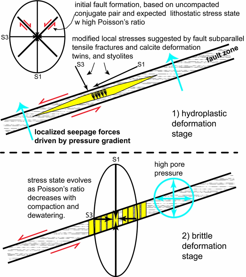
Figure 9. Model discussed in the text for mechanical evolution of the Kvalpynten growth basin faults at the detachment level.
As mentioned, this initial enigma can be solved by calling upon localized seepage forces driven by fluid flow that results from pore pressure and permeability gradients, which causes reorientation of the local stress field (Cobbold & Rodrigues, Reference Cobbold and Rodrigues2007; Cobbold, Durand & Mourgues, Reference Cobbold, Durand and Mourgues2010; Cobbold et al. Reference Cobbold, Zanella, Rodrigues and Løseth2013). In this context, fine-grained sediment with significant water content would have a high Poisson's ratio, resulting in a lithostatic stress field with a lower differential stress. In such a setting even small subvertical seepage forces may become crucial in reversing principal stresses, contributing to both non-lithified hydroplastic faulting (e.g. by reducing the local detachment-level fault-normal traction) and subhorizontal CIC vein development. Cobbold, Clark & Løseth (Reference Cobbold, Clark and Løseth2009) suggest that seepage forces aid the shallow detachment faulting seen in the Niger Delta. This process could also explain why locally the CIC and BF arrays follow the lower detachment surface. Extensional faulting could: (1) generate pore pressure gradients due to unloading; (2) develop a permeability barrier by hydroplastic rearrangement of phyllosilicates into fault-parallel membranes; and (3) juxtapose muds from a higher level with a lower fluid pressure against those lower with a higher fluid pressure. The expected seepage flow would then be across the slip zone, promoting continued movement. Both the stress state and pore pressures would have been quite different for the higher and steeper portions of the fault system, which only display hydroplastic fault rocks without carbonate mineralization or a brittle overprint.
During the earlier deformation phase undulose extinction, recrystallization or other evidence of deformation would not be expected in the CIC aggregates. Instead, deformation would be partitioned into the adjacent weaker, unlithified sediment. However, as lithification of the host sediment progressed by compaction and dewatering, there would be less strain partitioning between the CIC and the host material and locally existing CIC/BF aggregates would then be influenced by strain. The observed calcite deformation twins, which can grow at low deviatoric stresses (Lacombe, Reference Lacombe2010), and weak undulose extinction due to intracrystalline strain in some CIC, are attributed to this transition. The very thin character of the deformation twins is generally consistent with low temperature formation at shallow conditions (Ferrill et al. Reference Ferrill, Morris, Evans, Burkhard, Groshong and Onasch2004). The orientation of the stylolite seams (Fig. 8) and a qualitative interpretation of the observed conjugate deformation twins in the calcite are consistent with the maximum principal stress at a low angle to low-strength fault zones, suggesting general continuation of the fault-localized stress field that initially produced the CIC/BF aggregate as a tensile fracture.
In contrast, the microvein relays in the coarse calcite fill in the brittle faults (Figs 3, 8) imply a subhorizontal sigma-three (an overall stress regime consistent with normal faulting), a distinct change from the detachment stress conditions described previously in this section associated with CIC formation. The subhorizontal ‘elongate blocky’ calcite texture (Lander & Laubach, Reference Lander and Laubach2015) in the microvein relays are also consistent with a changed microfracture opening direction. The distinctive branching forms, with central, thin and subvertical fractures subperpendicular to the fault surface and connected to fault-parallel CIC vein aggregates, may track the transition between the two stress fields. A decrease in permeability would decrease the rate of seepage and the magnitude of seepage forces, and also allow for better seal development and maintenance of overpressures. With dewatering and lithification, Poisson's ratio should decrease; this would lead to a higher differential stress which would diminish the relative influence of subvertical seepage forces, and establish a stress field favouring subvertical veins. Finally, lithification driven by burial and dewatering would inhibit displacive growth of calcite, contributing to the different form of calcite mineralization for later-stage growth. A change in fracture opening versus crystal growth rate can also influence the form of mineralization (Lander & Laubach, Reference Lander and Laubach2015), which may also have played a role here.
The thin-section relationships indicate that fault slip and microvein formation are overlapping in time. The microveins are typically at a high angle, near 90° to the slip surface. Given a steep sigma-one in the tensile microvein plane at a very high angle to the slip plane, the inference is that the resolved shear component would be small. With slip surfaces of calcite on calcite, there is no reason to believe that the rock material was of particularly low strength; this leaves the maintenance of high fluid pressures during the later brittle phase of fault movement as the default explanation. A transition from fibrous and displacive carbonate growth to more equant, blocky spar associated with greater depths and reflecting progressive lithification is also suggested for concretions in Cretaceous sandstones of the US (McBride, Picard & Millikin, Reference McBride, Picard and Millikin2003).
7. Conclusions
Cone-in-cone and beef calcite mineral growths that are relatively common in the Triassic strata at Edgøya formed concurrently with faulting, locally ornamenting the fault surfaces at burial depths of <300 m. A working model for the formation of these fibrous calcite aggregates is nucleation along pre-existing carbonate material, including bedding-parallel and fault-parallel tensile fractures during a hydroplastic deformation phase. The consumption of sulphate during biogenic pyrite generation could aid calcite saturation and growth. An irregular stepped fibrous growing front incorporated trains of sediment and fluid inclusions at interior corners to form cone walls, displacing the unlithified sediment. Fluid flow directions and easier upwards displacement caused growth to be preferentially (but not solely) upwards, creating asymmetric antitaxial vein aggregates. Seepage forces, and possibly displacive crystal growth, aided subcritical tensile fracture propagation in a locally altered stress field that may have contributed to detachment zone weakening. Seepage forces and shallow conditions could explain principal stress reorientation within and at a low angle to the fault zone.
With fluid flow, compaction and lithification, and attendant changes in Poisson's ratio and permeability, the stress field, deformation style and nature of calcite mineralization changed to coarser calcite filling in fault-surface perpendicular relay microvein arrays associated with high pore pressures. The association of cone-in-cone and beef development with the transition from brittle to ductile faulting is consistent with the CIC/BF being a consequence of compaction, dewatering and lithification, as indicated by Sellés-Martínez (Reference Sellés-Martínez1994); however, the cone geometry is not mechanical in origin. The calcite mineralization at Edgeøya helps track the very significant changes in mechanical properties and stress states that can occur during this crucial transformation at very shallow crustal levels.
Acknowledgements
This work has been (partially) funded by the project ‘Reconstructing the Triassic Northern Barents shelf; basin infill patterns controlled by gentle sags and faults’ (Trias North; www.mn.uio.no/triasnorth/) under grant 234152 from the Research Council of Norway (RCN) and with financial support from Tullow Oil Norway, Lundin Norway, Statoil Petroleum, Edison Norway and RWE Dea Norway. Atle Mørk and an anonymous reviewer are thanked for their feedback that led to significant improvements. However, all errors remain those of the authors.
Declaration of interest
The authors are unaware of any conflicts of interest related to this article.


 Open access