


1. Introduction
Immiscible two-phase flow within capillary geometries is attracting increasing scientific and industrial interest due to its broad relevance in microfluidic devices (Shi, Mohibullah & Easley Reference Shi, Mohibullah and Easley2021), biological and healthcare systems (Sharkey et al. Reference Sharkey, White, Finocchiaro, Thomas, Estevam and Konry2024) and multiphase flow in porous media. In such confined flows, the fluid–fluid–solid contact line governs the balance between capillary forces (set by wettability) and viscous dissipation, thereby determining the contact-line velocity and, in turn, the evolving phase morphology and stability (Eggers Reference Eggers2004, Reference Eggers2005; Bonn et al. Reference Bonn, Eggers, Indekeu, Meunier and Rolley2009; Snoeijer & Andreotti Reference Snoeijer and Andreotti2013). The resulting moving contact line couples hydrodynamics to surface physicochemistry, which drives interfacial deformation and pinch-off (Eggers Reference Eggers2004). Resolving these dynamics is therefore essential for accurate prediction and robust operation of confined multiphase systems (Zhao, MacMinn & Juanes Reference Zhao, MacMinn and Juanes2016).
Fluid–fluid displacement with a high viscosity ratio in perfectly wetting capillary geometries, particularly in the context of viscous fingering, has been extensively studied since the seminal experiment of Taylor (Reference Taylor1961), which showed that air invading a capillary tube filled with a perfectly wetting viscous fluid leaves behind a film whose thickness is set by the finger velocity. Most subsequent studies also assumed perfect wetting, excluding contact-line motion (Garstecki, Stone & Whitesides Reference Garstecki, Stone and Whitesides2005), whereas recent experiments in partially wetting confinements reveal that contact-line-driven thin-film dynamics can produce new displacement and pinch-off mechanisms (Zhao et al. Reference Zhao, MacMinn and Juanes2016, Reference Zhao, Pahlavan, Cueto-Felgueroso and Juanes2018). The dynamics of thin-film breakup in partially wetting capillaries represents a fundamental problem in microfluidics. However, the influence of contact-line motion and surface-active contaminants (surfactants) on the onset of fluid–fluid rupture and on the dynamics leading up to the rupture has received limited attention, despite the central roles these factors play in microscale interfacial stability (Anna Reference Anna2016).
Zhao et al. (Reference Zhao, Pahlavan, Cueto-Felgueroso and Juanes2018) revisited the Taylor (Reference Taylor1961) experiment and showed that when the displacement capillary number,
 $\textit{Ca}=\mu _2 U/\gamma$
, where
$\textit{Ca}=\mu _2 U/\gamma$
, where
 $U$
is the mean displacement velocity,
$U$
is the mean displacement velocity,
 $\mu _2$
is the viscosity of the ‘defending’ phase and
$\mu _2$
is the viscosity of the ‘defending’ phase and
 $\gamma$
is the surface tension, exceeds a critical value
$\gamma$
is the surface tension, exceeds a critical value
 $\textit{Ca}^\ast$
, the interface becomes unstable, forming an axial finger and leaving a trailing film. Above the critical capillary number,
$\textit{Ca}^\ast$
, the interface becomes unstable, forming an axial finger and leaving a trailing film. Above the critical capillary number,
 $\textit{Ca}^\ast$
, the contact line moves at a constant velocity determined solely by the wettability. The resulting dewetting rim grows steadily until it undergoes rupture via a Rayleigh–Plateau instability. Pahlavan et al. (Reference Pahlavan, Stone, McKinley and Juanes2019) reported that at low
$\textit{Ca}^\ast$
, the contact line moves at a constant velocity determined solely by the wettability. The resulting dewetting rim grows steadily until it undergoes rupture via a Rayleigh–Plateau instability. Pahlavan et al. (Reference Pahlavan, Stone, McKinley and Juanes2019) reported that at low
 $\textit{Ca}$
values, bubble pinch-off in partially wetting tubes exhibits universal self-similar behaviour dominated by the contact-line singularity, contrasting with pinch-off in unbounded domains, which may retain memory of initial and boundary conditions (Doshi et al. Reference Doshi, Cohen, Zhang, Siegel, Howell, Basaran and Nagel2003).
$\textit{Ca}$
values, bubble pinch-off in partially wetting tubes exhibits universal self-similar behaviour dominated by the contact-line singularity, contrasting with pinch-off in unbounded domains, which may retain memory of initial and boundary conditions (Doshi et al. Reference Doshi, Cohen, Zhang, Siegel, Howell, Basaran and Nagel2003).
Although these experimental studies have provided novel insights into immiscible two-phase displacement in partially wetting confined geometries, simulations can offer a powerful complement by enabling detailed analysis of flow behaviour and access to parameters that are difficult to measure directly (Anthony et al. Reference Anthony2023). Gao et al. (Reference Gao, Liu, Feng, Ding and Lu2019) numerically investigated the forced wetting transition in a straight capillary tube modelled as a two-dimensional axisymmetric domain using a phase-field approach. While their method qualitatively reproduces the experimental observations of Zhao et al. (Reference Zhao, Pahlavan, Cueto-Felgueroso and Juanes2018), its inability to resolve the nanometric physical length scale results in significant quantitative discrepancies, including overestimated contact-line velocities and premature rim breakup. In a similar study, Esmaeilzadeh et al. (Reference Esmaeilzadeh, Qin, Riaz and Tchelepi2020) performed direct numerical simulations of forced wetting in a two-dimensional axisymmetric domain using a level-set-based method, incorporating a dynamic contact angle model to quantitatively reproduce the experimental trends observed by Zhao et al. (Reference Zhao, Pahlavan, Cueto-Felgueroso and Juanes2018).
Despite recent advances in resolving physics near moving contact lines, quantifying the separate and coupled roles of substrate wettability and surface-active agents (surfactants) in confined pinch-off remains challenging. Changes in wettability alone can trigger wetting transitions and pinch-off in capillaries (Callegari, Calvo & Hulin Reference Callegari, Calvo and Hulin2005; Snoeijer & Eggers Reference Snoeijer and Eggers2010; Zhao et al. Reference Zhao, Pahlavan, Cueto-Felgueroso and Juanes2018; Pahlavan et al. Reference Pahlavan, Stone, McKinley and Juanes2019). In turn, insoluble surfactants modify interfacial tension and drive Marangoni stresses that alter neck thinning, particularly in capillary confinements (McGough & Basaran Reference McGough and Basaran2006; Wee et al. Reference Wee, Wagoner, Garg, Kamat and Basaran2021, Reference Wee, Kumar, Liu and Basaran2024). This study presents direct numerical simulations of a moving contact line within a straight circular capillary tube, explicitly addressing both the influence of substrate wettability on the pinch-off dynamics and the role of insoluble surfactants in modulating interfacial behaviour.
2. Problem formulation, numerical method and validation
The simulation configuration and flow parameters are chosen to closely replicate the experimental set-up of Zhao et al. (Reference Zhao, Pahlavan, Cueto-Felgueroso and Juanes2018), as illustrated in figure 1(a). A Newtonian fluid of viscosity
 $\mu _1$
and density
$\mu _1$
and density
 $\rho _1$
advances through a straight circular tube of diameter
$\rho _1$
advances through a straight circular tube of diameter
 $D$
and length
$D$
and length
 $L=20D$
(aspect ratio
$L=20D$
(aspect ratio
 $L/D=20$
), displacing a highly viscous defending fluid with
$L/D=20$
), displacing a highly viscous defending fluid with
 $\mu _2 =10^5\mu _1$
and density
$\mu _2 =10^5\mu _1$
and density
 $\rho _2 = 10^3\rho _1$
. The displacement is driven by prescribing a fully developed Poiseuille profile at the outlet boundary,
$\rho _2 = 10^3\rho _1$
. The displacement is driven by prescribing a fully developed Poiseuille profile at the outlet boundary,
 $U_{\textit{out}}(r)=2U (1-{r^2}/{R^2} )$
, where
$U_{\textit{out}}(r)=2U (1-{r^2}/{R^2} )$
, where
 $U$
is the cross-sectional mean velocity,
$U$
is the cross-sectional mean velocity,
 $r$
is the radial distance from the tube axis and
$r$
is the radial distance from the tube axis and
 $R=D/2$
is the tube radius
$R=D/2$
is the tube radius
 $(0 \leqslant r \leqslant R)$
.
$(0 \leqslant r \leqslant R)$
.
The flow dynamics in our simulations lies in the viscous–capillary Stokes regime, characterised by a low Reynolds number,
 ${Re}=\rho _{2}UD/\mu _{2}=\mathcal{O}(10^{-3})\ll 1$
, a high Ohnesorge number,
${Re}=\rho _{2}UD/\mu _{2}=\mathcal{O}(10^{-3})\ll 1$
, a high Ohnesorge number,
 $\textit{Oh}=\mu _{2}/\sqrt {\rho _{2}\gamma D}=\mathcal{O}(10)\gg 1$
, and a low Weber number,
$\textit{Oh}=\mu _{2}/\sqrt {\rho _{2}\gamma D}=\mathcal{O}(10)\gg 1$
, and a low Weber number,
 $\textit{We}=\rho _{2}U^{2}D/\gamma =\mathcal{O}(10^{-4})\ll 1$
, with negligible gravity, a low Bond number,
$\textit{We}=\rho _{2}U^{2}D/\gamma =\mathcal{O}(10^{-4})\ll 1$
, with negligible gravity, a low Bond number,
 ${Bo}=\Delta \rho \, g D^{2}/\gamma \approx \mathcal{O}(10^{-2})\ll 1$
, where
${Bo}=\Delta \rho \, g D^{2}/\gamma \approx \mathcal{O}(10^{-2})\ll 1$
, where
 $g$
is the gravitational acceleration.
$g$
is the gravitational acceleration.
For
 $\textit{Ca} \gt \textit{Ca}^\ast$
, a wettability transition occurs, destabilising the fluid–fluid interface and leaving behind a trailing film of the defending fluid on the solid wall (Eggers Reference Eggers2004). The thickness of the entrained film,
$\textit{Ca} \gt \textit{Ca}^\ast$
, a wettability transition occurs, destabilising the fluid–fluid interface and leaving behind a trailing film of the defending fluid on the solid wall (Eggers Reference Eggers2004). The thickness of the entrained film,
 $h_{\!{f}}$
, depends solely on the finger tip velocity,
$h_{\!{f}}$
, depends solely on the finger tip velocity,
 $U_{\textit{tip}}$
, following the empirical equation presented by Aussillous & Quéré (Reference Aussillous and Quéré2000),
$U_{\textit{tip}}$
, following the empirical equation presented by Aussillous & Quéré (Reference Aussillous and Quéré2000),
 $h_{\!{f}}/D=0.67 { Ca}^{2/3}_{\textit{tip}}/(1+2.5\times 1.34\textit{Ca}^{2/3}_{\textit{tip}})$
, where
$h_{\!{f}}/D=0.67 { Ca}^{2/3}_{\textit{tip}}/(1+2.5\times 1.34\textit{Ca}^{2/3}_{\textit{tip}})$
, where
 $\textit{Ca}_{\textit{tip}}= \mu _2U_{\textit{tip}}/\gamma$
represents the finger capillary number. The film then recedes, forming a growing rim with maximum thickness
$\textit{Ca}_{\textit{tip}}= \mu _2U_{\textit{tip}}/\gamma$
represents the finger capillary number. The film then recedes, forming a growing rim with maximum thickness
 $h_{\textit{max}}$
ahead of the moving contact line, where the fluid–fluid interface meets the solid wall at a finite contact angle
$h_{\textit{max}}$
ahead of the moving contact line, where the fluid–fluid interface meets the solid wall at a finite contact angle
 $\theta$
.
$\theta$
.
The dynamics of the system is illustrated in figure 1(b–d), where an initially flat interface becomes unstable due to a wettability transition, leading to the formation of a dewetting rim and the entrainment of a thin film of the defending fluid with thickness
 $h_{\!{f}}$
along the tube wall, as the interface tip and contact line propagate at velocities
$h_{\!{f}}$
along the tube wall, as the interface tip and contact line propagate at velocities
 $U_{\textit{tip}}$
and
$U_{\textit{tip}}$
and
 $U_{{cl}}$
, respectively. Ultimately, this results in pinch-off and the formation of an elongated ‘bubble’ (we use this term instead of ‘drop’ since
$U_{{cl}}$
, respectively. Ultimately, this results in pinch-off and the formation of an elongated ‘bubble’ (we use this term instead of ‘drop’ since
 $\rho_2\gg \rho_1$
and
$\rho_2\gg \rho_1$
and
 $\mu _2 \gg \mu _1$
) of the displacing fluid with length
$\mu _2 \gg \mu _1$
) of the displacing fluid with length
 $l_{{b}}$
. For simulation cases with surface-active agents, we consider an insoluble surfactant that remains confined to the interface without exchange with the bulk and solid phases. This is possible for situations wherein the sorption kinetics time scales far exceed those of the flow.
$l_{{b}}$
. For simulation cases with surface-active agents, we consider an insoluble surfactant that remains confined to the interface without exchange with the bulk and solid phases. This is possible for situations wherein the sorption kinetics time scales far exceed those of the flow.
(a) Simulation set-up for immiscible fluid–fluid displacement in a cylindrical capillary of diameter
 $D$
, where Fluid 1 (
$D$
, where Fluid 1 (
 $\rho _1, \mu _1$
) displaces Fluid 2 (
$\rho _1, \mu _1$
) displaces Fluid 2 (
 $\rho _2, \mu _2$
), while a parabolic velocity profile with mean velocity
$\rho _2, \mu _2$
), while a parabolic velocity profile with mean velocity
 $U$
is imposed at the outlet; the interface tip and contact line advance at
$U$
is imposed at the outlet; the interface tip and contact line advance at
 $U_{\textit{tip}}$
and
$U_{\textit{tip}}$
and
 $U_{ {cl}}$
, respectively. A thin film of the viscous defending fluid (thickness
$U_{ {cl}}$
, respectively. A thin film of the viscous defending fluid (thickness
 $h_{\!{f}}$
) is entrained. Inset: the contact-line region showing the dewetting rim, a finite contact angle
$h_{\!{f}}$
) is entrained. Inset: the contact-line region showing the dewetting rim, a finite contact angle
 $\theta$
, maximum height
$\theta$
, maximum height
 $h_{{max}}$
and
$h_{{max}}$
and
 $h_{\!{f}}$
. (b–d) Interface evolution: (b) initial flat interface, (c) dewetting rim and film entrainment due to contact-line motion and unstable frontal displacement and (d) formation of a displacing-fluid ‘bubble’ of length
$h_{\!{f}}$
. (b–d) Interface evolution: (b) initial flat interface, (c) dewetting rim and film entrainment due to contact-line motion and unstable frontal displacement and (d) formation of a displacing-fluid ‘bubble’ of length
 $l_{{b}}$
after pinch-off.
$l_{{b}}$
after pinch-off.

We define the characteristic scales by taking the surface tension of the clean interface,
 $\gamma _c$
, as the surface tension scale, capillary tube diameter,
$\gamma _c$
, as the surface tension scale, capillary tube diameter,
 $D$
, as the length scale, the visco-capillary time,
$D$
, as the length scale, the visco-capillary time,
 $t_{ {c}} = \mu _2 D/ \gamma _c$
, as the time scale, the capillary pressure,
$t_{ {c}} = \mu _2 D/ \gamma _c$
, as the time scale, the capillary pressure,
 $p_{{c}} = \gamma _c / D$
, as the pressure scale and the saturation interfacial concentration,
$p_{{c}} = \gamma _c / D$
, as the pressure scale and the saturation interfacial concentration,
 $\varGamma _\infty$
, as the interfacial concentration scale. Assuming isothermal, incompressible and immiscible flow of two Newtonian fluids under negligible gravitational effects, the dimensionless continuity and momentum equations, derived using a single-fluid continuum approach, read
$\varGamma _\infty$
, as the interfacial concentration scale. Assuming isothermal, incompressible and immiscible flow of two Newtonian fluids under negligible gravitational effects, the dimensionless continuity and momentum equations, derived using a single-fluid continuum approach, read
 \begin{equation} \begin{gathered} \tilde {\boldsymbol{\nabla }} \boldsymbol{\cdot }\tilde {\boldsymbol{u}} = 0, \\ \frac {\tilde{\rho}}{\textit{Oh}^2} \left (\frac {\partial \tilde {\boldsymbol{u}}}{\partial \tilde {t}}+\tilde {\boldsymbol{u}} \boldsymbol{\cdot }\tilde {\boldsymbol{\nabla }}\tilde {\boldsymbol{u}}\right ) = -\tilde {\boldsymbol{\nabla }}\! \tilde {p} + \tilde {\boldsymbol{\nabla }} \boldsymbol{\cdot }\big (2 \tilde \mu \tilde {\boldsymbol D} \big) + \int _{\tilde {S}{(\tilde {t})}} \big ( \tilde {\gamma } \tilde {\kappa } \boldsymbol{n} + \tilde {\boldsymbol{\nabla} }_{\!s} \tilde {\gamma } \big ) \delta \big (\tilde {\boldsymbol{x}} - \tilde {\boldsymbol{x}}_s \big ) {\rm d}\tilde {S}. \end{gathered}\end{equation}
We use the tilde notation to indicate non-dimensional variables, where
 $\tilde {\boldsymbol{u}}$
and
$\tilde {\boldsymbol{u}}$
and
 $\tilde {p}$
represent the velocity vector and pressure, respectively;
$\tilde {p}$
represent the velocity vector and pressure, respectively;
 $\tilde {\boldsymbol{D}} = ({1}/{2})(\tilde {\boldsymbol{\nabla }} \tilde {\boldsymbol{u}} + \tilde {\boldsymbol{\nabla }} \tilde {\boldsymbol{u}}^T)$
is the strain-rate tensor;
$\tilde {\boldsymbol{D}} = ({1}/{2})(\tilde {\boldsymbol{\nabla }} \tilde {\boldsymbol{u}} + \tilde {\boldsymbol{\nabla }} \tilde {\boldsymbol{u}}^T)$
is the strain-rate tensor;
 $\tilde {\gamma }$
is the local surface tension;
$\tilde {\gamma }$
is the local surface tension;
 $\tilde {\kappa }$
is the interface curvature;
$\tilde {\kappa }$
is the interface curvature;
 $\tilde {\boldsymbol{\nabla} }_{\!s} = (\boldsymbol{I} - \boldsymbol{n}\boldsymbol{n}) \boldsymbol{\cdot }\tilde {\boldsymbol{\nabla }}$
denotes the surface gradient operator, where
$\tilde {\boldsymbol{\nabla} }_{\!s} = (\boldsymbol{I} - \boldsymbol{n}\boldsymbol{n}) \boldsymbol{\cdot }\tilde {\boldsymbol{\nabla }}$
denotes the surface gradient operator, where
 $\boldsymbol{I}$
is the identity tensor and
$\boldsymbol{I}$
is the identity tensor and
 $\boldsymbol{n}$
is the unit normal to the interface;
$\boldsymbol{n}$
is the unit normal to the interface;
 $\delta (\tilde {\boldsymbol{x}} - \tilde {\boldsymbol{x}}_s)$
is a three-dimensional Dirac distribution non-zero only at the fluid–fluid interface, where
$\delta (\tilde {\boldsymbol{x}} - \tilde {\boldsymbol{x}}_s)$
is a three-dimensional Dirac distribution non-zero only at the fluid–fluid interface, where
 $\tilde {\boldsymbol{x}}$
denotes the spatial position vector and
$\tilde {\boldsymbol{x}}$
denotes the spatial position vector and
 $\tilde {\boldsymbol{x}}_s$
is the interface location;
$\tilde {\boldsymbol{x}}_s$
is the interface location;
 $\tilde {S}(\tilde {t})$
represents the interface area at time
$\tilde {S}(\tilde {t})$
represents the interface area at time
 $\tilde {t}$
; and
$\tilde {t}$
; and
 $\tilde {\mu } = \mu _1/\mu _2 + (1 - \mu _1/\mu _2)\mathcal{H}(\tilde {\boldsymbol{x}}, \tilde {t})$
is the local viscosity;
$\tilde {\mu } = \mu _1/\mu _2 + (1 - \mu _1/\mu _2)\mathcal{H}(\tilde {\boldsymbol{x}}, \tilde {t})$
is the local viscosity;
 $\tilde{\rho} = \rho_1/\rho_2 + (1 - \rho_1/\rho_2)\mathcal{H}(\tilde{\boldsymbol{x}}, \tilde{t})$
is the local density, where
$\tilde{\rho} = \rho_1/\rho_2 + (1 - \rho_1/\rho_2)\mathcal{H}(\tilde{\boldsymbol{x}}, \tilde{t})$
is the local density, where
 $\mathcal{H}$
is a smoothed Heaviside function equal to
$\mathcal{H}$
is a smoothed Heaviside function equal to
 $0$
in the displacing fluid and
$0$
in the displacing fluid and
 $1$
in the defending fluid. The Ohnesorge number
$1$
in the defending fluid. The Ohnesorge number
 $ \textit{Oh} = \mu _2/{\sqrt {\rho _2\gamma _cD}}$
represents the ratio of viscous to inertial and surface tension forces.
$ \textit{Oh} = \mu _2/{\sqrt {\rho _2\gamma _cD}}$
represents the ratio of viscous to inertial and surface tension forces.
We model an insoluble surfactant confined to the fluid–fluid interface,
 $\tilde {S}(\tilde t)$
, with no adsorption/desorption to either bulk phase or the solid wall at the contact line. The interfacial concentration,
$\tilde {S}(\tilde t)$
, with no adsorption/desorption to either bulk phase or the solid wall at the contact line. The interfacial concentration,
 $\tilde {\varGamma }$
, evolves according to the following advection–diffusion equation:
$\tilde {\varGamma }$
, evolves according to the following advection–diffusion equation:
 \begin{equation} \frac {\partial \tilde {\varGamma }}{\partial \tilde {t}} + \tilde {\boldsymbol{\nabla} }_{\!s} \boldsymbol{\cdot }(\tilde {\boldsymbol{u}}\tilde {\varGamma }) = \frac {1}{\textit{Pe}} \tilde {{\nabla} }_s^2 \tilde {\varGamma }, \end{equation}
where
 $\textit{Pe} = \gamma _c D / (\mu _2 D_s)$
is the Peclet number, representing the ratio of convective to diffusive transport of surfactant monomers along the interface, and
$\textit{Pe} = \gamma _c D / (\mu _2 D_s)$
is the Peclet number, representing the ratio of convective to diffusive transport of surfactant monomers along the interface, and
 $D_s$
denotes the surface diffusivity. We set the initial condition as a uniform coverage of surfactant concentration of
$D_s$
denotes the surface diffusivity. We set the initial condition as a uniform coverage of surfactant concentration of
 $\tilde \varGamma _0 = \varGamma _0/\varGamma _\infty = 0.5$
over the entire interface at time zero,
$\tilde \varGamma _0 = \varGamma _0/\varGamma _\infty = 0.5$
over the entire interface at time zero,
 $\tilde {S}(0)$
. At the contact line, we impose zero total interfacial flux of surfactant:
$\tilde {S}(0)$
. At the contact line, we impose zero total interfacial flux of surfactant:
 \begin{equation} \boldsymbol{m}\boldsymbol{\cdot }\Big [\tilde {\varGamma }(\tilde {\boldsymbol{u}}-\tilde {\boldsymbol{u}_{{cl}}})-\frac {1}{\textit{Pe}}\,\tilde {\boldsymbol{\nabla} }_{\!s} \tilde {\varGamma }\Big ]=0, \end{equation}
where
 $\boldsymbol{m}$
is the unit co-normal (tangent to the interface and normal to the contact line). Under the assumption that the contact line moves with the same velocity as interfacial (tangential) velocity, this boundary condition can be implemented as a Neumann boundary condition for
$\boldsymbol{m}$
is the unit co-normal (tangent to the interface and normal to the contact line). Under the assumption that the contact line moves with the same velocity as interfacial (tangential) velocity, this boundary condition can be implemented as a Neumann boundary condition for
 $\tilde {\varGamma }$
at the contact line:
$\tilde {\varGamma }$
at the contact line:
 \begin{equation} \boldsymbol{m}\boldsymbol{\cdot }\tilde {\boldsymbol{\nabla} }_{\!s} \tilde {\varGamma }=0. \end{equation}
These conditions imply conservation of the total interfacial surfactant:
 \begin{equation} \frac {\rm d}{{\rm d}\tilde t}\int _{\tilde S(\tilde t)} \tilde {\varGamma }\,{\rm d}\tilde S = 0. \end{equation}
Equations (2.1) and (2.2) are coupled via the nonlinear Langmuir equation of state (Berg Reference Berg2010):
 \begin{equation} \tilde {\gamma } = 1 + \beta _s \ln (1 - \tilde {\varGamma }), \end{equation}
where
 $\beta _s = \mathcal{R} T \varGamma _{\infty } / \gamma _c$
is the elasticity parameter, quantifying the sensitivity of surface tension to changes in surface concentration, with
$\beta _s = \mathcal{R} T \varGamma _{\infty } / \gamma _c$
is the elasticity parameter, quantifying the sensitivity of surface tension to changes in surface concentration, with
 $\mathcal{R}$
denoting the universal gas constant and
$\mathcal{R}$
denoting the universal gas constant and
 $T$
the absolute temperature.
$T$
the absolute temperature.
To eliminate the stress singularity at the moving contact line, we adopt the generalised Navier boundary condition introduced by Qian, Wang & Sheng (Reference Qian, Wang and Sheng2003), which is derived from insights gained through molecular dynamics simulations. This boundary condition, applied in the immediate vicinity of the contact line, relates the contact-line velocity,
 $\tilde {\boldsymbol{u}}_{{cl}}$
, interpreted as the wall-tangential slip velocity at the solid boundary, to the sum of tangential stresses, incorporating contributions from both viscous shear stress and the unbalanced Young’s stress (Qian et al. Reference Qian, Wang and Sheng2003; Shin et al. Reference Shin, Chergui and Juric2018a
):
$\tilde {\boldsymbol{u}}_{{cl}}$
, interpreted as the wall-tangential slip velocity at the solid boundary, to the sum of tangential stresses, incorporating contributions from both viscous shear stress and the unbalanced Young’s stress (Qian et al. Reference Qian, Wang and Sheng2003; Shin et al. Reference Shin, Chergui and Juric2018a
):
 \begin{equation} \tilde {\boldsymbol{u}}_{{cl}} = \tilde \lambda \left ( \boldsymbol{n_w}\boldsymbol{\cdot }2\tilde {\boldsymbol{D}}\boldsymbol{\cdot }\boldsymbol{t_w}+ \frac {\tilde \gamma \left (\cos \theta _{\textit{ext}}-\cos \theta _{{ con}}\right )}{\tilde {\mu }\tilde {\varDelta }} \right )\boldsymbol t_w, \end{equation}
where
 $\boldsymbol{n_w}$
and
$\boldsymbol{n_w}$
and
 $\boldsymbol{t_w}$
represent the unit vectors normal to and along the direction of the substrate,
$\boldsymbol{t_w}$
represent the unit vectors normal to and along the direction of the substrate,
 $\tilde {\varDelta }$
is the size of a grid cell and
$\tilde {\varDelta }$
is the size of a grid cell and
 $\tilde \lambda \gt 0$
is the slip length set to
$\tilde \lambda \gt 0$
is the slip length set to
 $0.1\tilde {\varDelta }$
. As shown in figure 2(a),
$0.1\tilde {\varDelta }$
. As shown in figure 2(a),
 $\theta _{\textit{con}}$
is the numerical/dynamic contact angle measured between a level-set-based reconstructed interface and the solid wall,
$\theta _{\textit{con}}$
is the numerical/dynamic contact angle measured between a level-set-based reconstructed interface and the solid wall,
 $\theta _{\textit{con}}=\arccos (\boldsymbol{n}_{{w}}\boldsymbol{\cdot }\boldsymbol{n}_{\!{f}})$
, where
$\theta _{\textit{con}}=\arccos (\boldsymbol{n}_{{w}}\boldsymbol{\cdot }\boldsymbol{n}_{\!{f}})$
, where
 $\boldsymbol{n}_{\!{f}}$
is the interface unit normal near the wall. Angle
$\boldsymbol{n}_{\!{f}}$
is the interface unit normal near the wall. Angle
 $\theta _{\textit{ext}}$
is the extended contact angle that imposes macroscopic contact angle hysteresis as
$\theta _{\textit{ext}}$
is the extended contact angle that imposes macroscopic contact angle hysteresis as
 \begin{equation} \theta _{\textit{ext}} = \begin{cases} \theta _{{adv}}, & \text{if } \theta _{\textit{con}} \gt \theta _{{adv}}, \\[3pt] \theta _{\textit{rec}}, & \text{if } \theta _{\textit{con}} \lt \theta _{\textit{rec}}, \\[3pt] \theta _{\textit{rec}} \lt \theta \lt \theta _{{adv}}, & \textrm {otherwise,} \end{cases} \end{equation}
where
 $\theta _{{adv}}$
and
$\theta _{{adv}}$
and
 $\theta _{\textit{rec}}$
are the macroscopic advancing and receding contact angles, respectively. For this study, we set
$\theta _{\textit{rec}}$
are the macroscopic advancing and receding contact angles, respectively. For this study, we set
 $\theta _{{adv}} \approx \theta _{\textit{rec}} = \theta _{{e}}$
, where
$\theta _{{adv}} \approx \theta _{\textit{rec}} = \theta _{{e}}$
, where
 $\theta _{{e}}$
is the macroscopic equilibrium or static contact angle on the solid wall. Equation (2.7) sets the contact-line velocity strictly tangential to the wall,
$\theta _{{e}}$
is the macroscopic equilibrium or static contact angle on the solid wall. Equation (2.7) sets the contact-line velocity strictly tangential to the wall,
 $\tilde {\boldsymbol{u}}_{{cl}}\parallel \boldsymbol t_w$
. The magnitude and direction of
$\tilde {\boldsymbol{u}}_{{cl}}\parallel \boldsymbol t_w$
. The magnitude and direction of
 $\tilde {\boldsymbol{u}}_{{cl}}$
along the solid wall are determined by the sign of the sum of viscous shear and unbalanced Young’s stress terms. Positive wall-tangential viscous shear (
$\tilde {\boldsymbol{u}}_{{cl}}$
along the solid wall are determined by the sign of the sum of viscous shear and unbalanced Young’s stress terms. Positive wall-tangential viscous shear (
 $\boldsymbol n_w\boldsymbol{\cdot }\tilde {\boldsymbol D}\boldsymbol{\cdot }\boldsymbol t_w\gt 0$
, with
$\boldsymbol n_w\boldsymbol{\cdot }\tilde {\boldsymbol D}\boldsymbol{\cdot }\boldsymbol t_w\gt 0$
, with
 $\boldsymbol n_w$
pointing from the solid wall into the fluid) drives motion in
$\boldsymbol n_w$
pointing from the solid wall into the fluid) drives motion in
 $+\boldsymbol t_w$
, whereas a negative shear drives motion in
$+\boldsymbol t_w$
, whereas a negative shear drives motion in
 $-\boldsymbol t_w$
. The capillary imbalance contributes algebraically to reinforce or oppose the viscous term. As illustrated in figure 2(b), the contribution from the unbalanced Young’s stress is set by
$-\boldsymbol t_w$
. The capillary imbalance contributes algebraically to reinforce or oppose the viscous term. As illustrated in figure 2(b), the contribution from the unbalanced Young’s stress is set by
 $\Delta \cos \equiv \cos \theta _{\textit{ext}}-\cos \theta _{\textit{con}}$
, increasing the magnitude of the contact-line velocity,
$\Delta \cos \equiv \cos \theta _{\textit{ext}}-\cos \theta _{\textit{con}}$
, increasing the magnitude of the contact-line velocity,
 $\tilde {\boldsymbol{u}}_{{cl}}$
, along
$\tilde {\boldsymbol{u}}_{{cl}}$
, along
 $\boldsymbol{t}_{\mathrm w}$
for
$\boldsymbol{t}_{\mathrm w}$
for
 $\Delta \cos \gt 0$
, decreasing it for
$\Delta \cos \gt 0$
, decreasing it for
 $\Delta \cos \lt 0$
and vanishing for
$\Delta \cos \lt 0$
and vanishing for
 $\Delta \cos =0$
. Therefore, whenever
$\Delta \cos =0$
. Therefore, whenever
 $\Delta \cos \neq 0$
the imbalance term implicitly acts to drive
$\Delta \cos \neq 0$
the imbalance term implicitly acts to drive
 $\theta _{\textit{con}}$
towards
$\theta _{\textit{con}}$
towards
 $\theta _{\textit{ext}}$
.
$\theta _{\textit{ext}}$
.
(a) Schematic of a moving contact point with velocity of
 $\tilde {\boldsymbol{u}}_{{cl}}$
on a solid wall in an immiscible fluid–fluid system with bulk velocity of
$\tilde {\boldsymbol{u}}_{{cl}}$
on a solid wall in an immiscible fluid–fluid system with bulk velocity of
 $\tilde {\boldsymbol{u}}$
:
$\tilde {\boldsymbol{u}}$
:
 $\boldsymbol{n}_{{w}}$
and
$\boldsymbol{n}_{{w}}$
and
 $\boldsymbol{t}_{{w}}$
denote the unit vectors normal and tangential to the wall, respectively. From a sharp level-set contour (blue, dashed) a piece-wise linear dynamic interface (black, solid) is reconstructed. At the wall, with unit vectors
$\boldsymbol{t}_{{w}}$
denote the unit vectors normal and tangential to the wall, respectively. From a sharp level-set contour (blue, dashed) a piece-wise linear dynamic interface (black, solid) is reconstructed. At the wall, with unit vectors
 $\boldsymbol{n}_{{w}}$
(normal) and
$\boldsymbol{n}_{{w}}$
(normal) and
 $\boldsymbol{t}_{{w}}$
(tangent), the numerical/dynamic contact angle is measured from this reconstructed interface as
$\boldsymbol{t}_{{w}}$
(tangent), the numerical/dynamic contact angle is measured from this reconstructed interface as
 $\theta _{\textit{con}}=\arccos (\boldsymbol{n}_{{w}}\boldsymbol{\cdot }\boldsymbol{n}_{\!{f}})$
, where
$\theta _{\textit{con}}=\arccos (\boldsymbol{n}_{{w}}\boldsymbol{\cdot }\boldsymbol{n}_{\!{f}})$
, where
 $\boldsymbol{n}_{\!{f}}$
is the interface unit normal near the wall. Angle
$\boldsymbol{n}_{\!{f}}$
is the interface unit normal near the wall. Angle
 $\theta _{\textit{ext}}$
is the extended contact angle set to impose the physical macroscopic hysteresis contact angle at the contact line. (b) The strength of the unbalanced Young’s term, (2.7), scales with
$\theta _{\textit{ext}}$
is the extended contact angle set to impose the physical macroscopic hysteresis contact angle at the contact line. (b) The strength of the unbalanced Young’s term, (2.7), scales with
 $\Delta \cos =\cos \theta _{\textit{ext}}-\cos \theta _{\textit{con}}$
: it increases the magnitude of
$\Delta \cos =\cos \theta _{\textit{ext}}-\cos \theta _{\textit{con}}$
: it increases the magnitude of
 $\tilde {\boldsymbol{u}}_{{cl}}$
along
$\tilde {\boldsymbol{u}}_{{cl}}$
along
 $\boldsymbol{t}_{ w}$
for
$\boldsymbol{t}_{ w}$
for
 $\Delta \cos \gt 0$
, decreases it for
$\Delta \cos \gt 0$
, decreases it for
 $\Delta \cos \lt 0$
and vanishes at
$\Delta \cos \lt 0$
and vanishes at
 $\Delta \cos =0$
, thereby driving
$\Delta \cos =0$
, thereby driving
 $\theta _{\textit{con}}$
towards
$\theta _{\textit{con}}$
towards
 $\theta _{\textit{ext}}$
.
$\theta _{\textit{ext}}$
.

We employ a hybrid interface-tracking level-set method known as the level contour reconstruction method to numerically solve the flow governing equations in a three-dimensional uniform Cartesian computational domain. The fluid–fluid interface is represented by a Lagrangian triangular mesh, reconstructed from a level-set field and advected via second-order Runge–Kutta. We refer the reader to Shin et al. (Reference Shin, Chergui and Juric2018a
,Reference Shin, Chergui, Juric, Kahouadji, Matar and Craster
b
) (and references therein) for a comprehensive description of the numerical framework. Throughout this study, we use a uniform mesh with spacing
 $\tilde {\varDelta }=\varDelta /D=1/64$
, and the Navier slip length is set equal to
$\tilde {\varDelta }=\varDelta /D=1/64$
, and the Navier slip length is set equal to
 $\tilde \lambda =0.05\tilde {\varDelta }$
. These numerical choices of mesh resolution and slip length follow the previous study of Shin et al. (Reference Shin, Chergui and Juric2018a
), where the same numerical framework and contact-line model are validated and the influence of
$\tilde \lambda =0.05\tilde {\varDelta }$
. These numerical choices of mesh resolution and slip length follow the previous study of Shin et al. (Reference Shin, Chergui and Juric2018a
), where the same numerical framework and contact-line model are validated and the influence of
 $\tilde \lambda$
and mesh size on macroscopic contact-line velocity is analysed.
$\tilde \lambda$
and mesh size on macroscopic contact-line velocity is analysed.
Validation of the present numerical model against experimental, analytical and previous numerical results. (a) Dimensionless contact-line velocity,
 $Ca_{cl}$
, versus imposed displacement velocity,
$Ca_{cl}$
, versus imposed displacement velocity,
 $Ca$
. Present simulations are compared with the experiments of Zhao et al. (Reference Zhao, Pahlavan, Cueto-Felgueroso and Juanes2018) and the direct numerical simulations of Gao et al. (Reference Gao, Liu, Feng, Ding and Lu2019), Esmaeilzadeh et al. (Reference Esmaeilzadeh, Qin, Riaz and Tchelepi2020) and Qiu et al. (Reference Qiu, Cueto-Felgueroso, Pahlavan, Primkulov and Juanes2025) for
$Ca$
. Present simulations are compared with the experiments of Zhao et al. (Reference Zhao, Pahlavan, Cueto-Felgueroso and Juanes2018) and the direct numerical simulations of Gao et al. (Reference Gao, Liu, Feng, Ding and Lu2019), Esmaeilzadeh et al. (Reference Esmaeilzadeh, Qin, Riaz and Tchelepi2020) and Qiu et al. (Reference Qiu, Cueto-Felgueroso, Pahlavan, Primkulov and Juanes2025) for
 $\theta _{{e}}=68^\circ$
. The solid line represents the identity reference
$\theta _{{e}}=68^\circ$
. The solid line represents the identity reference
 $Ca_{cl}=Ca$
. (b) Non-dimensional bubble length,
$Ca_{cl}=Ca$
. (b) Non-dimensional bubble length,
 $\tilde {l}_{{b}}$
, versus finger-tip velocity,
$\tilde {l}_{{b}}$
, versus finger-tip velocity,
 $Ca_{\textit{tip}}$
, showing agreement with Zhao et al. (Reference Zhao, Pahlavan, Cueto-Felgueroso and Juanes2018) and the analytical prediction of Gao et al. (Reference Gao, Liu, Feng, Ding and Lu2019) for
$Ca_{\textit{tip}}$
, showing agreement with Zhao et al. (Reference Zhao, Pahlavan, Cueto-Felgueroso and Juanes2018) and the analytical prediction of Gao et al. (Reference Gao, Liu, Feng, Ding and Lu2019) for
 $\theta _{{e}}=68^\circ$
. (c) Non-dimensional finger-tip velocity,
$\theta _{{e}}=68^\circ$
. (c) Non-dimensional finger-tip velocity,
 $Ca_{\textit{tip}}$
, versus imposed displacement velocity,
$Ca_{\textit{tip}}$
, versus imposed displacement velocity,
 $\textit{Ca}$
, for
$\textit{Ca}$
, for
 $\theta _{ {e}}=68^\circ$
and
$\theta _{ {e}}=68^\circ$
and
 $28^\circ$
, validated against the analytical solution proposed by Gao et al. (Reference Gao, Liu, Feng, Ding and Lu2019). (d) Non-dimensional deposited-film thickness,
$28^\circ$
, validated against the analytical solution proposed by Gao et al. (Reference Gao, Liu, Feng, Ding and Lu2019). (d) Non-dimensional deposited-film thickness,
 $\tilde {h}_{\!{f}}$
, versus finger-tip velocity,
$\tilde {h}_{\!{f}}$
, versus finger-tip velocity,
 $Ca_{\textit{tip}}$
, compared with the generalised Taylor–Bretherton model (Aussillous & Quéré Reference Aussillous and Quéré2000) for both contact angles,
$Ca_{\textit{tip}}$
, compared with the generalised Taylor–Bretherton model (Aussillous & Quéré Reference Aussillous and Quéré2000) for both contact angles,
 $\theta _{{e}}=68^\circ$
and
$\theta _{{e}}=68^\circ$
and
 $28^\circ$
. Here, ‘Exp.’ denotes experimental measurements, ‘Sim.’ denotes results from our numerical simulations and ‘Analyt.’ denotes analytical predictions.
$28^\circ$
. Here, ‘Exp.’ denotes experimental measurements, ‘Sim.’ denotes results from our numerical simulations and ‘Analyt.’ denotes analytical predictions.

We validate our numerical method for predicting contact-line motion and bubble pinch-off by comparing with the forced-dewetting experiments of Zhao et al. (Reference Zhao, Pahlavan, Cueto-Felgueroso and Juanes2018) in a capillary tube, using an immiscible fluid–fluid, visco-capillary-driven system with
 $\textit{Oh}=10$
,
$\textit{Oh}=10$
,
 $\mu _1/\mu _2=10^{-5}$
,
$\mu _1/\mu _2=10^{-5}$
,
 $\rho _1/\rho _2=10^{-3}$
and equilibrium contact angles
$\rho _1/\rho _2=10^{-3}$
and equilibrium contact angles
 $\theta _{{e}}=68^\circ$
and
$\theta _{{e}}=68^\circ$
and
 $28^\circ$
. Figure 3(a) compares our numerical results for the dimensionless contact-line velocity,
$28^\circ$
. Figure 3(a) compares our numerical results for the dimensionless contact-line velocity,
 $\textit{Ca}_{{cl}} = \mu _2 U_{{ cl}}/\gamma _c$
, across a range of dimensionless displacement velocities,
$\textit{Ca}_{{cl}} = \mu _2 U_{{ cl}}/\gamma _c$
, across a range of dimensionless displacement velocities,
 $\textit{Ca}$
, with the experimental data of Zhao et al. (Reference Zhao, Pahlavan, Cueto-Felgueroso and Juanes2018) for clean interfaces. Similarly to the experimental data, our simulations predict the existence of a critical displacement capillary number,
$\textit{Ca}$
, with the experimental data of Zhao et al. (Reference Zhao, Pahlavan, Cueto-Felgueroso and Juanes2018) for clean interfaces. Similarly to the experimental data, our simulations predict the existence of a critical displacement capillary number,
 ${ Ca}^\ast$
, above which the contact line moves at a constant velocity, independent of the flow velocity imposed at the outlet (Abdal et al. Reference Abdal, Panda, Kahouadji, Shams, Shin, Chergui, Juric and Matar2026). For
${ Ca}^\ast$
, above which the contact line moves at a constant velocity, independent of the flow velocity imposed at the outlet (Abdal et al. Reference Abdal, Panda, Kahouadji, Shams, Shin, Chergui, Juric and Matar2026). For
 $\textit{Ca} \gt \textit{Ca}^\ast$
, the fluid–fluid interface becomes unstable, causing the interface tip to advance at a dimensionless velocity
$\textit{Ca} \gt \textit{Ca}^\ast$
, the fluid–fluid interface becomes unstable, causing the interface tip to advance at a dimensionless velocity
 $\textit{Ca}_{\textit{tip}}$
and leave behind an entrained film of the defending liquid with thickness
$\textit{Ca}_{\textit{tip}}$
and leave behind an entrained film of the defending liquid with thickness
 $\tilde {h}_{{ f}}$
. This process eventually leads to pinch-off, forming a Taylor bubble of the displacing liquid with length
$\tilde {h}_{{ f}}$
. This process eventually leads to pinch-off, forming a Taylor bubble of the displacing liquid with length
 $\tilde {l}_{{ b}}$
, separated from the next bubble by a liquid slug of the defending fluid, as reported in Zhao et al. (Reference Zhao, Pahlavan, Cueto-Felgueroso and Juanes2018).
$\tilde {l}_{{ b}}$
, separated from the next bubble by a liquid slug of the defending fluid, as reported in Zhao et al. (Reference Zhao, Pahlavan, Cueto-Felgueroso and Juanes2018).
Moreover, figure 3(a) benchmarks the measured contact-line velocity,
 $\textit{Ca}_{{cl}}$
, from our simulations against the direct numerical simulations of Gao et al. (Reference Gao, Liu, Feng, Ding and Lu2019) and Esmaeilzadeh et al. (Reference Esmaeilzadeh, Qin, Riaz and Tchelepi2020) and the recent study of Qiu et al. (Reference Qiu, Cueto-Felgueroso, Pahlavan, Primkulov and Juanes2025). All the numerical approaches systematically overpredict the experimental
$\textit{Ca}_{{cl}}$
, from our simulations against the direct numerical simulations of Gao et al. (Reference Gao, Liu, Feng, Ding and Lu2019) and Esmaeilzadeh et al. (Reference Esmaeilzadeh, Qin, Riaz and Tchelepi2020) and the recent study of Qiu et al. (Reference Qiu, Cueto-Felgueroso, Pahlavan, Primkulov and Juanes2025). All the numerical approaches systematically overpredict the experimental
 $\textit{Ca}_{{cl}}$
. This trend is likely not specific to any one method, but rather reflects a broader limitation of continuum simulations of moving contact lines where the microscopic physics at the contact line is not resolved directly and must instead be regularised through modelling parameters, such as slip length, precursor-film thickness or diffuse-interface width. As a result, the effective contact-line dissipation in the simulations does not exactly match that of the physical system, particularly in the presence of surface roughness and contact-angle hysteresis. In our computations (and in Esmaeilzadeh et al. (Reference Esmaeilzadeh, Qin, Riaz and Tchelepi2020) and Qiu et al. (Reference Qiu, Cueto-Felgueroso, Pahlavan, Primkulov and Juanes2025)) the discrepancy is modest but persistent, with
$\textit{Ca}_{{cl}}$
. This trend is likely not specific to any one method, but rather reflects a broader limitation of continuum simulations of moving contact lines where the microscopic physics at the contact line is not resolved directly and must instead be regularised through modelling parameters, such as slip length, precursor-film thickness or diffuse-interface width. As a result, the effective contact-line dissipation in the simulations does not exactly match that of the physical system, particularly in the presence of surface roughness and contact-angle hysteresis. In our computations (and in Esmaeilzadeh et al. (Reference Esmaeilzadeh, Qin, Riaz and Tchelepi2020) and Qiu et al. (Reference Qiu, Cueto-Felgueroso, Pahlavan, Primkulov and Juanes2025)) the discrepancy is modest but persistent, with
 $\textit{Ca}^{\textit{numerical}}_{{cl}} \simeq 2\textit{Ca}^{\textit{experiment}}_{{cl}}$
across the simulated displacement capillary range. This bias can have a notable impact on the early-time pinching neck during dewetting-rim growth, which is controlled by the contact-line velocity, leading simulations to predict faster necking than what is observed experimentally.
$\textit{Ca}^{\textit{numerical}}_{{cl}} \simeq 2\textit{Ca}^{\textit{experiment}}_{{cl}}$
across the simulated displacement capillary range. This bias can have a notable impact on the early-time pinching neck during dewetting-rim growth, which is controlled by the contact-line velocity, leading simulations to predict faster necking than what is observed experimentally.
Figure 3(b) demonstrates that our simulated bubble length is in good agreement with the experimental data reported by Zhao et al. (Reference Zhao, Pahlavan, Cueto-Felgueroso and Juanes2018) for
 $\theta _{{e}}=68^\circ$
, as well as the theoretical equation proposed by Gao et al. (Reference Gao, Liu, Feng, Ding and Lu2019) for the bubble length,
$\theta _{{e}}=68^\circ$
, as well as the theoretical equation proposed by Gao et al. (Reference Gao, Liu, Feng, Ding and Lu2019) for the bubble length,
 $\tilde {l}_{{b}}=({a}/{8\tilde {h}_{\!{f}}}) (( {\textit{Ca}_{\textit{tip}}}/{\textit{Ca}_{{cl}}})-1 )$
, where
$\tilde {l}_{{b}}=({a}/{8\tilde {h}_{\!{f}}}) (( {\textit{Ca}_{\textit{tip}}}/{\textit{Ca}_{{cl}}})-1 )$
, where
 $a$
is a tuning parameter set to
$a$
is a tuning parameter set to
 $0.65$
and
$0.65$
and
 $\textit{Ca}_{{cl}}\approx 0.015$
is the critical capillary number adapted for
$\textit{Ca}_{{cl}}\approx 0.015$
is the critical capillary number adapted for
 $\theta _{{e}}=68^\circ$
. We further validate our simulation results by analysing the film thickness,
$\theta _{{e}}=68^\circ$
. We further validate our simulation results by analysing the film thickness,
 $\tilde {h}_{\!{f}}$
, and the interface tip velocity,
$\tilde {h}_{\!{f}}$
, and the interface tip velocity,
 $\textit{Ca}_{{ tip}}$
, across a wide range of displacement velocity,
$\textit{Ca}_{{ tip}}$
, across a wide range of displacement velocity,
 $\textit{Ca}$
, for both
$\textit{Ca}$
, for both
 $\theta _{{e}} = 28^\circ$
and
$\theta _{{e}} = 28^\circ$
and
 $\theta _{{ e}} = 68^\circ$
. Figure 3(c) shows
$\theta _{{ e}} = 68^\circ$
. Figure 3(c) shows
 $\textit{Ca}_{\textit{tip}}$
as a function of
$\textit{Ca}_{\textit{tip}}$
as a function of
 $\textit{Ca}$
, demonstrating a good agreement between the numerical simulation results and a theoretical prediction obtained based on a volume conservation analysis,
$\textit{Ca}$
, demonstrating a good agreement between the numerical simulation results and a theoretical prediction obtained based on a volume conservation analysis,
 $ { Ca}_{\textit{tip}}=\textit{Ca} ( 1-2\tilde {h}_{\!{f}} )^{-2}$
. As shown in figure 3(d), our simulation results recover the empirical scaling law proposed by Aussillous & Quéré (Reference Aussillous and Quéré2000), referred to as the generalised Taylor–Bretherton relationship,
$ { Ca}_{\textit{tip}}=\textit{Ca} ( 1-2\tilde {h}_{\!{f}} )^{-2}$
. As shown in figure 3(d), our simulation results recover the empirical scaling law proposed by Aussillous & Quéré (Reference Aussillous and Quéré2000), referred to as the generalised Taylor–Bretherton relationship,
 $ \tilde {h}_{\!{f}} = {0.67\textit{Ca}^{2/3}_{\textit{tip}}}/(1 + 2.5 \times 1.34\textit{Ca}^{2/3}_{\textit{tip}})$
.
$ \tilde {h}_{\!{f}} = {0.67\textit{Ca}^{2/3}_{\textit{tip}}}/(1 + 2.5 \times 1.34\textit{Ca}^{2/3}_{\textit{tip}})$
.
3. Results and discussion
We begin our discussion by analysing the impact of contact-line motion on the evolution of a surfactant-free interface, leading to pinch-off in the microcapillary tube. We consider a visco-capillary-driven fluid–fluid system characterised by
 $\textit{Oh} \gg 1$
, with viscosity and density ratios set to
$\textit{Oh} \gg 1$
, with viscosity and density ratios set to
 $\mu _1/\mu _2=10^{-5}$
and
$\mu _1/\mu _2=10^{-5}$
and
 $\rho _1/\rho _2=10^{-3}$
, respectively. We examine the impact of the wettability of the confinement by varying the equilibrium contact angle from strongly wetting to partially non-wetting cases, ranging from
$\rho _1/\rho _2=10^{-3}$
, respectively. We examine the impact of the wettability of the confinement by varying the equilibrium contact angle from strongly wetting to partially non-wetting cases, ranging from
 $\theta _{e}=30^{\circ }$
to
$\theta _{e}=30^{\circ }$
to
 $\theta _{e}=125^{\circ }$
. We establish a surfactant-free benchmark case, characterised by
$\theta _{e}=125^{\circ }$
. We establish a surfactant-free benchmark case, characterised by
 $\textit{Oh}=10$
,
$\textit{Oh}=10$
,
 $\textit{Ca}=0.1$
,
$\textit{Ca}=0.1$
,
 $\theta _{{ e}}=65^{\circ }$
,
$\theta _{{ e}}=65^{\circ }$
,
 $\mu _1/\mu _2=10^{-5}$
and
$\mu _1/\mu _2=10^{-5}$
and
 $\rho _1/\rho _2=10^{-3}$
, against which we compare the surfactant-laden cases. For the latter, we examine the impact of insoluble surfactants on the pinch-off evolution, where the surfactant remains confined to the interface without exchange with the bulk phase. We analyse its influence on the interfacial dynamics by varying the surfactant elasticity parameter,
$\rho _1/\rho _2=10^{-3}$
, against which we compare the surfactant-laden cases. For the latter, we examine the impact of insoluble surfactants on the pinch-off evolution, where the surfactant remains confined to the interface without exchange with the bulk phase. We analyse its influence on the interfacial dynamics by varying the surfactant elasticity parameter,
 $\beta _s$
.
$\beta _s$
.
In this study, within the visco-capillary pinching regime (
 $\textit{Oh}\gg 1$
), we focus on the early-time thinning of the bubble neck, rather than the late-time, near-singular pinch-off limit. The small-radius asymptotics and relevant canonical scalings are extensively studied in the literature (Papageorgiou Reference Papageorgiou1995; Brenner, Lister & Stone Reference Brenner, Lister and Stone1996; Eggers Reference Eggers1997; Day, Hinch & Lister Reference Day, Hinch and Lister1998; Chen, Notz & Basaran Reference Chen, Notz and Basaran2002; Notz & Basaran Reference Notz and Basaran2004; Burton, Waldrep & Taborek Reference Burton, Waldrep and Taborek2005; McGough & Basaran Reference McGough and Basaran2006; Eggers et al. Reference Eggers, Fontelos, Leppinen and Snoeijer2007; Gekle et al. Reference Gekle, Snoeijer, Lohse and van der Meer2009; Wee et al. Reference Wee, Wagoner, Garg, Kamat and Basaran2021, Reference Wee, Anthony and Basaran2022). To keep our fully three-dimensional computations tractable, we concentrate resolution near the moving contact line and prioritise fidelity in capturing the contact-line physics, rather than the ultimate singular scales. Consequently, we do not attempt to extract a multi-decade neck-thinning scaling from our direct numerical simulations, as in Pahlavan et al. (Reference Pahlavan, Stone, McKinley and Juanes2019). Our aim is to quantify how wettability and insoluble surfactants shape the early-time interfacial dynamics.
$\textit{Oh}\gg 1$
), we focus on the early-time thinning of the bubble neck, rather than the late-time, near-singular pinch-off limit. The small-radius asymptotics and relevant canonical scalings are extensively studied in the literature (Papageorgiou Reference Papageorgiou1995; Brenner, Lister & Stone Reference Brenner, Lister and Stone1996; Eggers Reference Eggers1997; Day, Hinch & Lister Reference Day, Hinch and Lister1998; Chen, Notz & Basaran Reference Chen, Notz and Basaran2002; Notz & Basaran Reference Notz and Basaran2004; Burton, Waldrep & Taborek Reference Burton, Waldrep and Taborek2005; McGough & Basaran Reference McGough and Basaran2006; Eggers et al. Reference Eggers, Fontelos, Leppinen and Snoeijer2007; Gekle et al. Reference Gekle, Snoeijer, Lohse and van der Meer2009; Wee et al. Reference Wee, Wagoner, Garg, Kamat and Basaran2021, Reference Wee, Anthony and Basaran2022). To keep our fully three-dimensional computations tractable, we concentrate resolution near the moving contact line and prioritise fidelity in capturing the contact-line physics, rather than the ultimate singular scales. Consequently, we do not attempt to extract a multi-decade neck-thinning scaling from our direct numerical simulations, as in Pahlavan et al. (Reference Pahlavan, Stone, McKinley and Juanes2019). Our aim is to quantify how wettability and insoluble surfactants shape the early-time interfacial dynamics.
Evolution of the non-dimensional neck diameter,
 $2\tilde r_0$
, with time to pinch-off,
$2\tilde r_0$
, with time to pinch-off,
 $\tilde {\tau }$
. (a) For displacement capillary number
$\tilde {\tau }$
. (a) For displacement capillary number
 $\textit{Ca}=0.1$
(this work). (b) Impact of contact-line velocity,
$\textit{Ca}=0.1$
(this work). (b) Impact of contact-line velocity,
 $\textit{Ca}_{{cl}}$
, on scaling exponent. For
$\textit{Ca}_{{cl}}$
, on scaling exponent. For
 $\textit{Ca}_{{cl}}\approx 0.02$
(this work and Qiu et al. (Reference Qiu, Cueto-Felgueroso, Pahlavan, Primkulov and Juanes2025)), the data follow an effective scaling close to
$\textit{Ca}_{{cl}}\approx 0.02$
(this work and Qiu et al. (Reference Qiu, Cueto-Felgueroso, Pahlavan, Primkulov and Juanes2025)), the data follow an effective scaling close to
 $\tilde \tau ^{0.3}$
, whereas reducing the contact-line velocity to
$\tilde \tau ^{0.3}$
, whereas reducing the contact-line velocity to
 $\textit{Ca}_{{cl}}\approx 0.01$
(this work) and
$\textit{Ca}_{{cl}}\approx 0.01$
(this work) and
 $\textit{Ca}_{{cl}}\approx 0.015$
(Qiu et al. Reference Qiu, Cueto-Felgueroso, Pahlavan, Primkulov and Juanes2025) shifts the data towards the
$\textit{Ca}_{{cl}}\approx 0.015$
(Qiu et al. Reference Qiu, Cueto-Felgueroso, Pahlavan, Primkulov and Juanes2025) shifts the data towards the
 $\tilde \tau ^{1/5}$
scaling reported by Pahlavan et al. (Reference Pahlavan, Stone, McKinley and Juanes2019).
$\tilde \tau ^{1/5}$
scaling reported by Pahlavan et al. (Reference Pahlavan, Stone, McKinley and Juanes2019).

3.1. Surfactant-free (clean) interface
Figure 4(a) shows the evolution of the bubble neck diameter,
 $2\tilde {r}_0$
, as a function of the time to the pinch-off singularity,
$2\tilde {r}_0$
, as a function of the time to the pinch-off singularity,
 $\tilde {\tau } = \tilde {t}_0-\tilde {t}$
, where
$\tilde {\tau } = \tilde {t}_0-\tilde {t}$
, where
 $\tilde {t}_0$
is the pinch-off time, for the surfactant-free benchmark case (
$\tilde {t}_0$
is the pinch-off time, for the surfactant-free benchmark case (
 $\textit{Oh}=10$
,
$\textit{Oh}=10$
,
 $\textit{Ca}=0.1$
and
$\textit{Ca}=0.1$
and
 $\theta _{{e}}=65^\circ$
). The time evolution of the neck reveals that the bubble neck diameter follows a scaling exponent of
$\theta _{{e}}=65^\circ$
). The time evolution of the neck reveals that the bubble neck diameter follows a scaling exponent of
 $0.3$
within an early-time regime before transitioning to the point of pinch-off.
$0.3$
within an early-time regime before transitioning to the point of pinch-off.
The scaling exponent of
 $\tilde {\tau }^{0.3}$
measured from our direct numerical simulation deviates from the experimentally observed scaling of
$\tilde {\tau }^{0.3}$
measured from our direct numerical simulation deviates from the experimentally observed scaling of
 $\tilde {\tau }^{1/5}$
for the neck-diameter evolution during the pinch-off of a bubble confined in a microcapillary tube filled with a partially wetting viscous fluid, as reported by Pahlavan et al. (Reference Pahlavan, Stone, McKinley and Juanes2019). In our configuration, the departure from
$\tilde {\tau }^{1/5}$
for the neck-diameter evolution during the pinch-off of a bubble confined in a microcapillary tube filled with a partially wetting viscous fluid, as reported by Pahlavan et al. (Reference Pahlavan, Stone, McKinley and Juanes2019). In our configuration, the departure from
 $\tilde {r}_0 \sim \tilde {\tau }^{1/5}$
at early times is a direct consequence of the contact-line velocity as the relevant control parameter,
$\tilde {r}_0 \sim \tilde {\tau }^{1/5}$
at early times is a direct consequence of the contact-line velocity as the relevant control parameter,
 $\textit{Ca}_{{cl}}$
. To illustrate this dependence, figure 4(b) shows that cases with
$\textit{Ca}_{{cl}}$
. To illustrate this dependence, figure 4(b) shows that cases with
 $\textit{Ca}_{{cl}}\approx 0.02$
exhibit an effective scaling exponent close to
$\textit{Ca}_{{cl}}\approx 0.02$
exhibit an effective scaling exponent close to
 $0.3$
, whereas reducing
$0.3$
, whereas reducing
 $\textit{Ca}_{{cl}}$
shifts the measured exponent towards the
$\textit{Ca}_{{cl}}$
shifts the measured exponent towards the
 $\tilde {\tau }^{1/5}$
scaling reported by Pahlavan et al. (Reference Pahlavan, Stone, McKinley and Juanes2019). For the smallest contact-line velocity accessible in the present simulations, the effective fitted exponent is
$\tilde {\tau }^{1/5}$
scaling reported by Pahlavan et al. (Reference Pahlavan, Stone, McKinley and Juanes2019). For the smallest contact-line velocity accessible in the present simulations, the effective fitted exponent is
 $\approx 0.23$
, indicating a trend towards
$\approx 0.23$
, indicating a trend towards
 $1/5$
. This trend indicates that the early-time scaling exponent varies systematically with
$1/5$
. This trend indicates that the early-time scaling exponent varies systematically with
 $\textit{Ca}_{{cl}}$
, which in turn depends on the wettability of the solid substrate. Smaller contact-line velocities could, in principle, be achieved by prescribing substantially lower contact angles (
$\textit{Ca}_{{cl}}$
, which in turn depends on the wettability of the solid substrate. Smaller contact-line velocities could, in principle, be achieved by prescribing substantially lower contact angles (
 $\theta _{{e}}\lt 30^\circ$
). However, modelling such strongly wetting conditions within the present framework is numerically challenging and lies outside the range over which the current model parametrisation has been validated. A similar small-angle limitation has also been reported by Fullana et al. (Reference Fullana, Kulkarni, Fricke, Popinet, Afkhami, Bothe and Zaleski2026).
$\theta _{{e}}\lt 30^\circ$
). However, modelling such strongly wetting conditions within the present framework is numerically challenging and lies outside the range over which the current model parametrisation has been validated. A similar small-angle limitation has also been reported by Fullana et al. (Reference Fullana, Kulkarni, Fricke, Popinet, Afkhami, Bothe and Zaleski2026).
Consistent with Pahlavan et al. (Reference Pahlavan, Stone, McKinley and Juanes2019), figure 5 shows that bubble-neck shrinkage follows self-similar scaling during the early-time visco-capillary regime (
 $\textit{Oh}\gt 1$
). In particular, figure 5(a) shows that the scaling exponent is independent of the imposed displacement flow rate (quantified by
$\textit{Oh}\gt 1$
). In particular, figure 5(a) shows that the scaling exponent is independent of the imposed displacement flow rate (quantified by
 $\textit{Ca}$
), when length is scaled by
$\textit{Ca}$
), when length is scaled by
 $D$
and time by
$D$
and time by
 $t_c=\mu _2 D/\gamma_c$
, while figure 5(b) demonstrates that, for
$t_c=\mu _2 D/\gamma_c$
, while figure 5(b) demonstrates that, for
 $\textit{Oh}\in [5,25]$
, the scaling exponent is likewise insensitive to geometry and fluid parameters. The late-time, near-pinch-off regime and its scalings, both with and without a contact line, are well established (see Eggers, Sprittles & Snoeijer (Reference Eggers, Sprittles and Snoeijer2025) and references therein). Therefore, in this study, we concentrate on the early-time regime, where a contact-line-controlled dewetting rim forms and evolves with
$\textit{Oh}\in [5,25]$
, the scaling exponent is likewise insensitive to geometry and fluid parameters. The late-time, near-pinch-off regime and its scalings, both with and without a contact line, are well established (see Eggers, Sprittles & Snoeijer (Reference Eggers, Sprittles and Snoeijer2025) and references therein). Therefore, in this study, we concentrate on the early-time regime, where a contact-line-controlled dewetting rim forms and evolves with
 $\mathrm{d}\tilde {r}_0/\mathrm{d}\tilde {\tau } \sim\textit{Ca}_{{cl}}$
, setting the initial conditions for the later near-pinch-off dynamics (Pahlavan et al. Reference Pahlavan, Stone, McKinley and Juanes2019).
$\mathrm{d}\tilde {r}_0/\mathrm{d}\tilde {\tau } \sim\textit{Ca}_{{cl}}$
, setting the initial conditions for the later near-pinch-off dynamics (Pahlavan et al. Reference Pahlavan, Stone, McKinley and Juanes2019).
Evolution of the dimensionless neck diameter,
 $2\tilde r_0$
, with the dimensionless time to pinch-off,
$2\tilde r_0$
, with the dimensionless time to pinch-off,
 $\tilde {\tau }$
. (a) Varying the displacement capillary number over
$\tilde {\tau }$
. (a) Varying the displacement capillary number over
 $\textit{Ca}\in [0.075,0.15]$
has an insignificant effect on the pinch-off dynamics: curves for different
$\textit{Ca}\in [0.075,0.15]$
has an insignificant effect on the pinch-off dynamics: curves for different
 ${ Ca}$
collapse onto a self-similar curve. (b) Collapse of curves is observed when varying the Ohnesorge number over
${ Ca}$
collapse onto a self-similar curve. (b) Collapse of curves is observed when varying the Ohnesorge number over
 $\textit{Oh}\in [5,25]$
, indicating self-similarity of the thinning dynamics across viscous and geometric conditions.
$\textit{Oh}\in [5,25]$
, indicating self-similarity of the thinning dynamics across viscous and geometric conditions.

Figure 6 shows the effect of wettability on the early-time pinch-off dynamics. As the solid wall becomes less wetting to the defending fluid, i.e. as the equilibrium contact angle
 $\theta _{{e}}$
increases,
$\theta _{{e}}$
increases,
 $\textit{Ca}_{{cl}}$
increases. The minimum neck radius correspondingly follows a wettability-dependent exponent
$\textit{Ca}_{{cl}}$
increases. The minimum neck radius correspondingly follows a wettability-dependent exponent
 $\alpha$
, which increases from values close to
$\alpha$
, which increases from values close to
 $1/5$
at small
$1/5$
at small
 $\textit{Ca}_{{cl}}$
to values approaching
$\textit{Ca}_{{cl}}$
to values approaching
 $1/2$
at larger
$1/2$
at larger
 $\textit{Ca}_{{cl}}$
. By contrast, the axial neck scale is much less sensitive to wettability and remains well described by
$\textit{Ca}_{{cl}}$
. By contrast, the axial neck scale is much less sensitive to wettability and remains well described by
 $\beta \approx 1/5$
. These results therefore show that wettability modifies the radial similarity class, while leaving the axial scaling essentially unchanged over the range examined here.
$\beta \approx 1/5$
. These results therefore show that wettability modifies the radial similarity class, while leaving the axial scaling essentially unchanged over the range examined here.
We next use the reduced long-wave framework of Pahlavan et al. (Reference Pahlavan, Stone, McKinley and Juanes2019) to examine whether the observed wettability dependence of
 $\alpha$
can be captured within a standard lubrication description, which recovers the asymptotic lubrication-limit similarity
$\alpha$
can be captured within a standard lubrication description, which recovers the asymptotic lubrication-limit similarity
 $\alpha =\beta =1/5$
. We introduce the ansatz
$\alpha =\beta =1/5$
. We introduce the ansatz
 \begin{equation} \tilde H=\tilde \tau ^\alpha \xi (\zeta ), \quad \zeta =\frac {\tilde z-\tilde z_0}{\tilde \tau ^\beta }, \qquad \tilde \tau =\tilde t_0-\tilde t, \end{equation}
where
 $\tilde H = 1-\tilde h_{\!f}$
and
$\tilde H = 1-\tilde h_{\!f}$
and
 $\tilde z_0$
denotes the axial pinch-off location. As detailed in the supplementary material available at https://doi.org/10.1017/jfm.2026.11583, incorporating wettability or contact-line motion into the long-wave model through a slip boundary condition at the solid wall, or through an additional flux term, does not alter the leading-order similarity balance, because the capillary-driven flux remains the dominant singular contribution. The reduced model therefore continues to select the asymptotic radial exponent
$\tilde z_0$
denotes the axial pinch-off location. As detailed in the supplementary material available at https://doi.org/10.1017/jfm.2026.11583, incorporating wettability or contact-line motion into the long-wave model through a slip boundary condition at the solid wall, or through an additional flux term, does not alter the leading-order similarity balance, because the capillary-driven flux remains the dominant singular contribution. The reduced model therefore continues to select the asymptotic radial exponent
 $\alpha =1/5$
, independent of wettability. This indicates that the wettability dependence of
$\alpha =1/5$
, independent of wettability. This indicates that the wettability dependence of
 $\alpha$
cannot be captured as a subdominant flux correction within the standard long-wave closure, but instead reflects contact-line physics that must enter the description more fundamentally. In particular, the observed variation of
$\alpha$
cannot be captured as a subdominant flux correction within the standard long-wave closure, but instead reflects contact-line physics that must enter the description more fundamentally. In particular, the observed variation of
 $\alpha$
likely depends on the detailed local flow near the contact line and its coupling to the pinch-off region, features that are not resolved within the long-wave-based reduced model. Deriving this dependence theoretically would therefore likely require a similarity analysis of the full Stokes equations with the inclusion of the contact-line region, which lies beyond the scope of the present work.
$\alpha$
likely depends on the detailed local flow near the contact line and its coupling to the pinch-off region, features that are not resolved within the long-wave-based reduced model. Deriving this dependence theoretically would therefore likely require a similarity analysis of the full Stokes equations with the inclusion of the contact-line region, which lies beyond the scope of the present work.
Effect of wettability on the pinch-off dynamics. (a) Contact-line capillary number,
 $\textit{Ca}_{{cl}}$
, as a function of equilibrium contact angle,
$\textit{Ca}_{{cl}}$
, as a function of equilibrium contact angle,
 $\theta _{{e}}$
;
$\theta _{{e}}$
;
 $\textit{Ca}_{{cl}}$
increases monotonically as the tube becomes less wetting to the defending fluid. (b) Evolution of the minimum bubble neck diameter,
$\textit{Ca}_{{cl}}$
increases monotonically as the tube becomes less wetting to the defending fluid. (b) Evolution of the minimum bubble neck diameter,
 $2\tilde r_0$
, with time to pinch-off,
$2\tilde r_0$
, with time to pinch-off,
 $\tilde \tau$
, for different
$\tilde \tau$
, for different
 $\textit{Ca}_{{cl}}$
. (c) Collapse of the axial neck position,
$\textit{Ca}_{{cl}}$
. (c) Collapse of the axial neck position,
 $\tilde z-\tilde z_0$
, against
$\tilde z-\tilde z_0$
, against
 $\tilde \tau$
, indicating a consistent axial scaling exponent
$\tilde \tau$
, indicating a consistent axial scaling exponent
 $\beta \approx 1/5$
across the wettability range. (d) Scaling exponents as a function of
$\beta \approx 1/5$
across the wettability range. (d) Scaling exponents as a function of
 $\textit{Ca}_{{cl}}$
: the neck-radius exponent
$\textit{Ca}_{{cl}}$
: the neck-radius exponent
 $\alpha$
increases with
$\alpha$
increases with
 $\textit{Ca}_{{cl}}$
, approaching
$\textit{Ca}_{{cl}}$
, approaching
 $1/2$
, while the axial exponent
$1/2$
, while the axial exponent
 $\beta$
remains approximately constant at
$\beta$
remains approximately constant at
 $1/5$
.
$1/5$
.

3.2. Surfactant-covered (insoluble) interface
We consider an insoluble surfactant confined solely to the interface. We set the saturated surfactant concentration at the critical micelle concentration to
 $\varGamma _\infty$
, while the initial surfactant coverage is set to
$\varGamma _\infty$
, while the initial surfactant coverage is set to
 $\varGamma _0=0.5\varGamma _{\infty }$
. The impact of the insoluble surfactant on interfacial dynamics is examined by varying the surfactant elasticity parameter within the range
$\varGamma _0=0.5\varGamma _{\infty }$
. The impact of the insoluble surfactant on interfacial dynamics is examined by varying the surfactant elasticity parameter within the range
 $\beta _s \in (0.0,1.0)$
. The Peclet number is fixed at
$\beta _s \in (0.0,1.0)$
. The Peclet number is fixed at
 $\textit{Pe} = \gamma _c D/\mu _2D_s=10^3$
to reflect convection-dominated monomer transport relative to surface diffusion. This value is chosen based on previous findings of Constante-Amores et al. (Reference Constante-Amores, Batchvarov, Kahouadji, Shin, Chergui and Matar2021), which showed that interfacial dynamics becomes weakly dependent on Pe for values exceeding
$\textit{Pe} = \gamma _c D/\mu _2D_s=10^3$
to reflect convection-dominated monomer transport relative to surface diffusion. This value is chosen based on previous findings of Constante-Amores et al. (Reference Constante-Amores, Batchvarov, Kahouadji, Shin, Chergui and Matar2021), which showed that interfacial dynamics becomes weakly dependent on Pe for values exceeding
 $\sim \mathcal{O}(10^2)$
, making
$\sim \mathcal{O}(10^2)$
, making
 $\textit{Pe}=10^{3}$
a representative, yet computationally tractable choice. The hydrodynamic parameters are set following the surfactant-free benchmark case (
$\textit{Pe}=10^{3}$
a representative, yet computationally tractable choice. The hydrodynamic parameters are set following the surfactant-free benchmark case (
 $\textit{Oh}=10$
,
$\textit{Oh}=10$
,
 $\textit{Ca}=0.1$
and
$\textit{Ca}=0.1$
and
 $\theta _{{e}}=65^\circ$
). The influence of surfactant monomers on the wettability of the confining surface, such as changes in the contact angle due to adsorption, is neglected in this study because monomers are absent from the bulk phase and the region near the contact line.
$\theta _{{e}}=65^\circ$
). The influence of surfactant monomers on the wettability of the confining surface, such as changes in the contact angle due to adsorption, is neglected in this study because monomers are absent from the bulk phase and the region near the contact line.
Figure 7(a) illustrates the effect of surfactant elasticity
 $\beta _s$
on the normalised contact-line velocity
$\beta _s$
on the normalised contact-line velocity
 $\textit{Ca}_{ { cl}}/\textit{Ca}_{{cl},\textit{clean}}$
, where normalisation is done with respect to the clean case (
$\textit{Ca}_{ { cl}}/\textit{Ca}_{{cl},\textit{clean}}$
, where normalisation is done with respect to the clean case (
 $\beta _s=0$
, no surfactants). Following Kamat et al. (Reference Kamat, Wagoner, Thete and Basaran2018), to isolate the effect of Marangoni stresses from the influence of surface tension reduction, we suppress Marangoni stresses by neglecting surface tension gradients due to surfactant concentration variations,
$\beta _s=0$
, no surfactants). Following Kamat et al. (Reference Kamat, Wagoner, Thete and Basaran2018), to isolate the effect of Marangoni stresses from the influence of surface tension reduction, we suppress Marangoni stresses by neglecting surface tension gradients due to surfactant concentration variations,
 $\tilde {\nabla} _s\tilde \gamma =\boldsymbol{0}$
, while retaining surfactant-induced lowering of surface tension
$\tilde {\nabla} _s\tilde \gamma =\boldsymbol{0}$
, while retaining surfactant-induced lowering of surface tension
 $\tilde \gamma$
via the equation of state (Kamat et al. Reference Kamat, Wagoner, Castrejón-Pita, Castrejón-Pita, Anthony and Basaran2020; Constante-Amores et al. Reference Constante-Amores, Batchvarov, Kahouadji, Shin, Chergui and Matar2021, Reference Constante-Amores, Chergui, Shin, Juric, Castrejón-Pita and Castrejón-Pita2022). When Marangoni stresses are suppressed (
$\tilde \gamma$
via the equation of state (Kamat et al. Reference Kamat, Wagoner, Castrejón-Pita, Castrejón-Pita, Anthony and Basaran2020; Constante-Amores et al. Reference Constante-Amores, Batchvarov, Kahouadji, Shin, Chergui and Matar2021, Reference Constante-Amores, Chergui, Shin, Juric, Castrejón-Pita and Castrejón-Pita2022). When Marangoni stresses are suppressed (
 $\tilde {\sigma }_{\textit{Ma}} = 0$
), the contact-line velocity remains nearly constant across all
$\tilde {\sigma }_{\textit{Ma}} = 0$
), the contact-line velocity remains nearly constant across all
 $\beta _s$
, indicating minimal impact from surface tension reduction alone. In contrast, when Marangoni stresses are active (
$\beta _s$
, indicating minimal impact from surface tension reduction alone. In contrast, when Marangoni stresses are active (
 $\tilde {\sigma }_{\textit{Ma}} \neq 0$
), the contact-line velocity decreases monotonically with increasing
$\tilde {\sigma }_{\textit{Ma}} \neq 0$
), the contact-line velocity decreases monotonically with increasing
 $\beta _s$
, showing a reduction of about
$\beta _s$
, showing a reduction of about
 $20\,\%$
at
$20\,\%$
at
 $\beta _s = 0.9$
, compared with the clean case. This confirms that the surfactant-induced Marangoni stress is the primary mechanism slowing the contact line in the presence of insoluble surfactants. Figure 7(b) shows the bubble length upon pinch-off,
$\beta _s = 0.9$
, compared with the clean case. This confirms that the surfactant-induced Marangoni stress is the primary mechanism slowing the contact line in the presence of insoluble surfactants. Figure 7(b) shows the bubble length upon pinch-off,
 $\tilde {l}_{{b}}$
, as a function of surfactant elasticity,
$\tilde {l}_{{b}}$
, as a function of surfactant elasticity,
 $\beta _s$
, highlighting the direct consequence of the contact-line velocity on the pinch-off time of the rim. As Marangoni stresses become stronger with increasing
$\beta _s$
, highlighting the direct consequence of the contact-line velocity on the pinch-off time of the rim. As Marangoni stresses become stronger with increasing
 $\beta _s$
, the slower contact-line motion delays the rim neck pinch-off, leading to longer pinch-off bubbles. In contrast, when Marangoni stresses are deactivated, the contact-line velocity remains unchanged and, expectedly, the pinch-off length shows minimal variations.
$\beta _s$
, the slower contact-line motion delays the rim neck pinch-off, leading to longer pinch-off bubbles. In contrast, when Marangoni stresses are deactivated, the contact-line velocity remains unchanged and, expectedly, the pinch-off length shows minimal variations.
Effect of surfactant elasticity,
 $\beta _s$
, on contact-line motion and neck evolution. (a) The normalised contact-line capillary number,
$\beta _s$
, on contact-line motion and neck evolution. (a) The normalised contact-line capillary number,
 $Ca_{{cl}}/Ca_{\textit{cl,clean}}$
, decreases with increasing
$Ca_{{cl}}/Ca_{\textit{cl,clean}}$
, decreases with increasing
 $\beta _s$
, with a stronger reduction when Marangoni stresses are present (
$\beta _s$
, with a stronger reduction when Marangoni stresses are present (
 $\tilde {\sigma }_{\textit{Ma}}\neq 0$
) than when absent (
$\tilde {\sigma }_{\textit{Ma}}\neq 0$
) than when absent (
 $\tilde {\sigma }_{\textit{Ma}}=0$
). (b) The non-dimensional bubble length after pinch-off,
$\tilde {\sigma }_{\textit{Ma}}=0$
). (b) The non-dimensional bubble length after pinch-off,
 $\tilde {l}_b$
, increases with
$\tilde {l}_b$
, increases with
 $\beta _s$
, more strongly for
$\beta _s$
, more strongly for
 $\tilde {\sigma }_{\textit{Ma}}\neq 0$
.
$\tilde {\sigma }_{\textit{Ma}}\neq 0$
.

Once the initially uniform surfactant distribution is disturbed, its subsequent redistribution is governed primarily by interfacial advection (
 $\textit{Pe}=10^3$
) and local variations in interfacial area. Near the moving contact line, the interface is stretched and the surface flow advects surfactant away from that region, leading to a reduction in the local surfactant concentration. Since diffusion is weak (
$\textit{Pe}=10^3$
) and local variations in interfacial area. Near the moving contact line, the interface is stretched and the surface flow advects surfactant away from that region, leading to a reduction in the local surfactant concentration. Since diffusion is weak (
 $\textit{Pe} \gg 1$
) and there is no bulk adsorption to replenish the interface, this depleted region near the contact line persists. By contrast, as the dewetting rim grows, the interfacial flow converges towards the dewetting rim region, producing surface compression and hence surfactant accumulation there. To clarify the physical mechanism responsible for this redistribution, figure 8 shows the interfacial surfactant concentration together with the surface velocity at two representative times of
$\textit{Pe} \gg 1$
) and there is no bulk adsorption to replenish the interface, this depleted region near the contact line persists. By contrast, as the dewetting rim grows, the interfacial flow converges towards the dewetting rim region, producing surface compression and hence surfactant accumulation there. To clarify the physical mechanism responsible for this redistribution, figure 8 shows the interfacial surfactant concentration together with the surface velocity at two representative times of
 $\tilde {\tau }=5.0$
and
$\tilde {\tau }=5.0$
and
 $\tilde {\tau }=50.0$
for insoluble surfactant of
$\tilde {\tau }=50.0$
for insoluble surfactant of
 $\beta _s=0.5$
.
$\beta _s=0.5$
.
Interfacial surfactant concentration
 $\tilde {\varGamma }$
(colour) and surface velocity
$\tilde {\varGamma }$
(colour) and surface velocity
 $\tilde {\boldsymbol{u}}_s$
(vectors) for
$\tilde {\boldsymbol{u}}_s$
(vectors) for
 $\textit{Pe}=10^3$
and
$\textit{Pe}=10^3$
and
 $\beta _s=0.5$
at (a)
$\beta _s=0.5$
at (a)
 $\tilde {\tau }=5.0$
and (b)
$\tilde {\tau }=5.0$
and (b)
 $\tilde {\tau }=50.0$
, showing surfactant depletion near the moving contact line and surfactant accumulation at the growing dewetting rim.
$\tilde {\tau }=50.0$
, showing surfactant depletion near the moving contact line and surfactant accumulation at the growing dewetting rim.

Influence of surfactant elasticity
 $\beta _s\in [0.0,0.9]$
on the fluid–fluid interface shape and dynamics near the contact line at
$\beta _s\in [0.0,0.9]$
on the fluid–fluid interface shape and dynamics near the contact line at
 $\tilde {\tau }=5.0$
. Profiles of (a) bubble neck diameter,
$\tilde {\tau }=5.0$
. Profiles of (a) bubble neck diameter,
 $2\tilde r_0$
, (b) surfactant concentration,
$2\tilde r_0$
, (b) surfactant concentration,
 $\tilde \varGamma$
, and (c) Marangoni stress,
$\tilde \varGamma$
, and (c) Marangoni stress,
 $\tilde \sigma _{\textit{Ma}}$
, plotted against the shifted axial coordinate,
$\tilde \sigma _{\textit{Ma}}$
, plotted against the shifted axial coordinate,
 $\tilde z-\tilde z_{{cl}}$
. Here
$\tilde z-\tilde z_{{cl}}$
. Here
 $\tilde z_{{cl}}$
denotes the contact-line position. (d) Contact-line velocity scales linearly with
$\tilde z_{{cl}}$
denotes the contact-line position. (d) Contact-line velocity scales linearly with
 $\beta _s$
, confirming
$\beta _s$
, confirming
 $(1 - \textit{Ca}_{{cl}}/ { Ca}_{ {cl,clean}}) \sim \beta _s$
.
$(1 - \textit{Ca}_{{cl}}/ { Ca}_{ {cl,clean}}) \sim \beta _s$
.

Figure 9 demonstrates how interfacial surfactant elasticity, parametrised by
 $\beta _s$
, modifies the bubble-neck dynamics and contact-line motion at
$\beta _s$
, modifies the bubble-neck dynamics and contact-line motion at
 $\tilde {\tau }=5$
. As shown in figure 9(a), increasing
$\tilde {\tau }=5$
. As shown in figure 9(a), increasing
 $\beta _s$
leaves the neck minimum essentially unchanged, while the downstream ridge is weakened and shifts downstream, producing a broader, smoother profile and a more gradual return to the far-field radius. The downstream stretch is driven by a positive Marangoni stress,
$\beta _s$
leaves the neck minimum essentially unchanged, while the downstream ridge is weakened and shifts downstream, producing a broader, smoother profile and a more gradual return to the far-field radius. The downstream stretch is driven by a positive Marangoni stress,
 $\tilde {\sigma }_{\textit{Ma}}\gt 0$
, as shown in figure 9(c). Figure 9(b) shows the surfactant concentration along the interface. Along the pinching neck the profile is well approximated by a parabola with a maximum at the pinch-off point,
$\tilde {\sigma }_{\textit{Ma}}\gt 0$
, as shown in figure 9(c). Figure 9(b) shows the surfactant concentration along the interface. Along the pinching neck the profile is well approximated by a parabola with a maximum at the pinch-off point,
 $\tilde {z}_0$
. In the region near the contact line, the interface is effectively clean,
$\tilde {z}_0$
. In the region near the contact line, the interface is effectively clean,
 $\tilde {\varGamma }\rvert _{{cl}}\approx 0$
, and the magnitude of the surfactant concentration gradient is roughly independent of
$\tilde {\varGamma }\rvert _{{cl}}\approx 0$
, and the magnitude of the surfactant concentration gradient is roughly independent of
 $\beta _s$
:
$\beta _s$
:
 \begin{equation} \partial _{\tilde s} \tilde \varGamma \rvert _{{cl}} \approx \text{constant in }\beta _s, \end{equation}
where
 $\partial _{\tilde s}$
is the surface-gradient operator. Figure 9(c) shows the interfacial Marangoni shear stress, which is bidirectional, compressive upstream of the concentration maximum and tensile downstream, with a zero crossing near the point of pinch-off,
$\partial _{\tilde s}$
is the surface-gradient operator. Figure 9(c) shows the interfacial Marangoni shear stress, which is bidirectional, compressive upstream of the concentration maximum and tensile downstream, with a zero crossing near the point of pinch-off,
 $\tilde z_0$
. It is clear that the magnitude of the stress increases monotonically with increasing
$\tilde z_0$
. It is clear that the magnitude of the stress increases monotonically with increasing
 $\beta _s$
.
$\beta _s$
.
Furthermore, figure 9(d) demonstrates the scaling behaviour of the reduction in normalised contact-line velocity due to surfactant elasticity,
 $1.0 - \textit{Ca}_{{cl}}/\textit{Ca}_{{cl},\textit{clean}}$
versus
$1.0 - \textit{Ca}_{{cl}}/\textit{Ca}_{{cl},\textit{clean}}$
versus
 $\beta _s$
. The numerical data reveal a linear relationship in the reduction of contact-line velocity, indicating that it scales approximately as
$\beta _s$
. The numerical data reveal a linear relationship in the reduction of contact-line velocity, indicating that it scales approximately as
 $ \beta _s$
. The observed linear scaling supports the theoretical prediction based on the local stress balance in the contact-line region. We consider the following stress scales acting near the contact-line region:
$ \beta _s$
. The observed linear scaling supports the theoretical prediction based on the local stress balance in the contact-line region. We consider the following stress scales acting near the contact-line region:
 \begin{equation} \tilde \sigma _{{vis}} \sim \frac {\tilde {\mu }\,\textit{Ca}_{{cl}}}{\tilde \ell },\quad \tilde \sigma_{\textit{cap}} \sim \frac {\tilde \gamma }{\tilde \ell },\quad \tilde \sigma _{\textit{Ma}} = -\partial _{\tilde s} \tilde \gamma = \frac {\beta _s}{1-\tilde \varGamma } \partial _{\tilde s} \tilde \varGamma . \end{equation}
Here,
 $\tilde \sigma _{{vis}}$
is the viscous shear stress scale associated with contact-line motion,
$\tilde \sigma _{{vis}}$
is the viscous shear stress scale associated with contact-line motion,
 $\tilde \sigma_{\textit{cap}}$
is the capillary driving stress scale (normal to the interface) and
$\tilde \sigma_{\textit{cap}}$
is the capillary driving stress scale (normal to the interface) and
 $\tilde \sigma _{\textit{Ma}}$
is the Marangoni shear stress arising from surface-tension gradients;
$\tilde \sigma _{\textit{Ma}}$
is the Marangoni shear stress arising from surface-tension gradients;
 $\tilde \ell$
is the local microscopic length scale.
$\tilde \ell$
is the local microscopic length scale.
For a clean interface (no surfactant), the viscous shear balances the capillary driving stress:
 \begin{equation} \frac {\tilde \mu \,\textit{Ca}_{\textit{cl,clean}}}{\tilde \ell } \approx \tilde \sigma_{\textit{cap}}. \end{equation}
In the presence of the surfactant, Marangoni shear opposes the motion of the contact line, as shown in figure 9(c):
 \begin{equation} \frac {\tilde \mu \,\textit{Ca}_{{cl}}}{\tilde \ell } \approx \tilde \sigma_{\textit{cap}} - \tilde \sigma _{\textit{Ma}}. \end{equation}
 \begin{equation} 1.0-\frac {\textit{Ca}_{{cl}}}{\textit{Ca}_{\textit{cl,clean}}} \approx \frac {\tilde \sigma _{\textit{Ma}}}{\tilde \sigma_{\textit{cap}}}. \end{equation}
Inserting the definition of
 $\tilde \sigma _{\textit{Ma}} = ( {\beta _s}/({1-\tilde \varGamma }))\partial _{\tilde s}\tilde {\varGamma }$
into (3.6) yields
$\tilde \sigma _{\textit{Ma}} = ( {\beta _s}/({1-\tilde \varGamma }))\partial _{\tilde s}\tilde {\varGamma }$
into (3.6) yields
 \begin{equation} 1.0-\frac {\textit{Ca}_{{cl}}}{\textit{Ca}_{ {cl,clean}}} \approx \frac {\partial _{\tilde s}\tilde \varGamma }{\tilde \sigma_{\textit{cap}}(1-\tilde \varGamma )}\beta _s. \end{equation}
Using (3.2), and given that near the contact-line region
 $\tilde \sigma _{ {cap}}$
and
$\tilde \sigma _{ {cap}}$
and
 $(1-\tilde \varGamma )$
do not vary strongly with
$(1-\tilde \varGamma )$
do not vary strongly with
 $\beta _s$
, see figure 9(b), we have
$\beta _s$
, see figure 9(b), we have
 \begin{equation} \frac {\tilde \partial _s\tilde \varGamma }{\tilde \sigma_{\textit{cap}}(1-\tilde \varGamma )} \approx \text{constant in }\beta _s. \end{equation}
Given (3.7) and (3.8), we obtain
 \begin{equation} \left (1.0-\frac {\textit{Ca}_{{cl}}}{\textit{Ca}_{\textit{cl,clean}}}\right ) \sim \beta _s. \end{equation}
Figure 10 shows the scaling behaviour of the evolution of the rim neck diameter,
 $ 2\tilde {r}_0$
, versus the time to pinch-off singularity,
$ 2\tilde {r}_0$
, versus the time to pinch-off singularity,
 $\tilde {\tau }$
, for various values of the surfactant elasticity parameter
$\tilde {\tau }$
, for various values of the surfactant elasticity parameter
 $\beta _s$
. Remarkably, all data collapse onto a single curve, independent of
$\beta _s$
. Remarkably, all data collapse onto a single curve, independent of
 $ \beta _s$
, indicating a behaviour similar to that in the clean case,
$ \beta _s$
, indicating a behaviour similar to that in the clean case,
 $\beta _s = 0$
, for a specific wettability.
$\beta _s = 0$
, for a specific wettability.
Time evolution of neck diameter,
 $2\tilde {r}_0$
, for varying surfactant elasticity,
$2\tilde {r}_0$
, for varying surfactant elasticity,
 $\beta _s$
. Curves for different
$\beta _s$
. Curves for different
 $\beta _s$
collapse onto a self-similar curve, demonstrating that surfactant elasticity over
$\beta _s$
collapse onto a self-similar curve, demonstrating that surfactant elasticity over
 $\beta _s\in [0.0,1.0]$
has an insignificant effect on the scaling of the pinch-off dynamics.
$\beta _s\in [0.0,1.0]$
has an insignificant effect on the scaling of the pinch-off dynamics.

This observed self-similarity, which persists regardless of the presence of surfactant, can be further understood by examining the dynamics of the growing dewetting rim. Following the approach of Pahlavan et al. (Reference Pahlavan, Stone, McKinley and Juanes2019), we analyse the emergence of self-similar behaviour in the presence of an insoluble surfactant using a long-wave approximation that assumes quasi-one-dimensional flow along the tube axis. We propose that the evolution of the interface exhibits self-similar behaviour, introducing the ansatz
 $\xi (\zeta )={\tilde H}/{\tilde \tau ^\alpha }$
,
$\xi (\zeta )={\tilde H}/{\tilde \tau ^\alpha }$
,
 $\zeta =({\tilde {z}-\tilde {z}_0})/{\tilde \tau ^\beta }$
and
$\zeta =({\tilde {z}-\tilde {z}_0})/{\tilde \tau ^\beta }$
and
 $G(\zeta )={\tilde {\varGamma }}/{\tilde \tau ^\psi }$
, where
$G(\zeta )={\tilde {\varGamma }}/{\tilde \tau ^\psi }$
, where
 $\psi$
is a scaling exponent. Substituting this ansatz into the governing equations for axial momentum and surfactant transport results in the following long-wave approximation for the evolution of the interface (see supplementary material for more details):
$\psi$
is a scaling exponent. Substituting this ansatz into the governing equations for axial momentum and surfactant transport results in the following long-wave approximation for the evolution of the interface (see supplementary material for more details):
 \begin{align} (-\alpha \xi +\beta \zeta \xi ')\tau ^{\alpha -1}= & -\frac {1}{16\xi }\left [\frac {\beta _s}{(1-G\tau ^\psi )}G'\left (\frac {\tau ^{\psi -2(\alpha +\beta )}}{\xi }-\xi ''\tau ^{\psi -4\beta }\right ) \right . \nonumber \\ & \left . +(1+\beta _s\ln (1-G\tau ^\psi ))\left (\frac {\xi '}{\xi ^2}\tau ^{-2(\alpha +\beta )}+\xi '''\tau ^{-4\beta }\right )\right ]'\!, \end{align}
indicating that the presence of an insoluble surfactant does not alter the fundamental self-similar scaling near pinch-off (see supplementary material).
To distinguish temporal self-similarity from the dependence of the similarity profile on surfactant elasticity, we first examine the interface evolution at fixed
 $\beta _s$
. Figure 11(a–d) presents neck profiles
$\beta _s$
. Figure 11(a–d) presents neck profiles
 $r(z,t)$
at several times approaching pinch-off for the clean case and for insoluble surfactant with elasticity
$r(z,t)$
at several times approaching pinch-off for the clean case and for insoluble surfactant with elasticity
 $\beta _s = 0.1$
,
$\beta _s = 0.1$
,
 $0.5$
and
$0.5$
and
 $0.9$
. Figure 11(e–h) shows the same profiles replotted using the similarity variables
$0.9$
. Figure 11(e–h) shows the same profiles replotted using the similarity variables
 $\hat {r} = r/r_0$
and
$\hat {r} = r/r_0$
and
 $\eta = (z-z_0)/\sqrt {r_0 r_c}$
, where
$\eta = (z-z_0)/\sqrt {r_0 r_c}$
, where
 $r_0$
is the minimum neck radius and
$r_0$
is the minimum neck radius and
 $r_c$
is the axial radius-of-curvature scale. The collapse of the profiles within each fixed-
$r_c$
is the axial radius-of-curvature scale. The collapse of the profiles within each fixed-
 $\beta _s$
set provides direct evidence of temporal self-similarity.
$\beta _s$
set provides direct evidence of temporal self-similarity.
Temporal self-similarity of the neck profile in the presence of surfactant. (a–d) Neck profiles
 $2r(z,t)$
plotted against
$2r(z,t)$
plotted against
 $(z-z_0)$
for the clean case and for
$(z-z_0)$
for the clean case and for
 $\beta _s=0.1$
,
$\beta _s=0.1$
,
 $0.5$
and
$0.5$
and
 $0.9$
; symbols denote multiple time snapshots, with increasing time in the direction of the arrow. (e–h) The same profiles replotted as
$0.9$
; symbols denote multiple time snapshots, with increasing time in the direction of the arrow. (e–h) The same profiles replotted as
 $r(z,t)/r_0(t)$
versus
$r(z,t)/r_0(t)$
versus
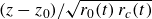 $(z-z_0)/\sqrt {r_0(t)\,r_c(t)}$
, where
$(z-z_0)/\sqrt {r_0(t)\,r_c(t)}$
, where
 $r_0(t)$
is the minimum neck radius and
$r_0(t)$
is the minimum neck radius and
 $r_c(t)$
is the axial radius-of-curvature scale. The collapse of the curves within each column demonstrates temporal self-similarity for fixed
$r_c(t)$
is the axial radius-of-curvature scale. The collapse of the curves within each column demonstrates temporal self-similarity for fixed
 $\beta _s$
.
$\beta _s$
.

Furthermore, as shown in figure 12, when the axial coordinate is rescaled as
 $(z-z_0)/\sqrt {r_0 r_c}$
, the profiles of the neck radius
$(z-z_0)/\sqrt {r_0 r_c}$
, the profiles of the neck radius
 $r/r_0$
, the normalised surfactant concentration
$r/r_0$
, the normalised surfactant concentration
 $\varGamma /\varGamma _{\textit{max}}$
and the Marangoni stress
$\varGamma /\varGamma _{\textit{max}}$
and the Marangoni stress
 $\tilde {\sigma }_{\textit{Ma}}$
exhibit only weak dependence on
$\tilde {\sigma }_{\textit{Ma}}$
exhibit only weak dependence on
 $\beta _s$
for
$\beta _s$
for
 $\beta _s \in [0,0.9]$
. This suggests that surfactant elasticity primarily alters the pinch-off time, while leaving the early-time similarity structure approximately unchanged.
$\beta _s \in [0,0.9]$
. This suggests that surfactant elasticity primarily alters the pinch-off time, while leaving the early-time similarity structure approximately unchanged.
Influence of surfactant elasticity,
 $\beta _s$
, on the interface dynamics of the bubble neck at
$\beta _s$
, on the interface dynamics of the bubble neck at
 $\tilde {\tau }=5.0$
. Profiles of (a) the normalised neck radius,
$\tilde {\tau }=5.0$
. Profiles of (a) the normalised neck radius,
 $r/r_0$
, (b) the normalised surfactant concentration,
$r/r_0$
, (b) the normalised surfactant concentration,
 $\varGamma /\varGamma _{\textit{max}}$
, and (c) the Marangoni stress,
$\varGamma /\varGamma _{\textit{max}}$
, and (c) the Marangoni stress,
 $\tilde {\sigma }_{\textit{Ma}}$
, plotted against the rescaled axial coordinate
$\tilde {\sigma }_{\textit{Ma}}$
, plotted against the rescaled axial coordinate
 $(z-z_0)/\sqrt {r_0 r_c}$
. Here,
$(z-z_0)/\sqrt {r_0 r_c}$
. Here,
 $r_0$
is the minimum neck radius at the reference time,
$r_0$
is the minimum neck radius at the reference time,
 $z_0$
is the axial location of the neck minimum and
$z_0$
is the axial location of the neck minimum and
 $r_c$
is the axial radius of curvature.
$r_c$
is the axial radius of curvature.

4. Conclusion
In this study, we performed direct numerical simulations to investigate the influence of contact-line motion, wettability and Marangoni stresses on the pinch-off dynamics of a highly viscous dewetting rim in a straight cylindrical capillary tube. The simulations were validated against prior experimental and analytical studies. For a surfactant-free interface, we identified an early-time self-similar regime where the neck thinning obeys a power law with a wettability-dependent exponent. We found that introducing an insoluble surfactant to the system modifies the local interfacial dynamics without disrupting the self-similar behaviour of the early-time regime. However, the timing and position of the pinch-off are affected. We observed that bidirectional Marangoni stresses reduce the steady contact-line velocity, thereby delaying pinch-off. Quantitatively, this velocity reduction follows a linear scaling with respect to the surfactant elasticity,
 $\beta _s$
, providing a predictive relationship for tuning flow behaviour in insoluble surfactant-laden systems.
$\beta _s$
, providing a predictive relationship for tuning flow behaviour in insoluble surfactant-laden systems.
Supplementary material
Supplementary material is available at https://doi.org/10.1017/jfm.2026.11583.
Acknowledgements
The authors acknowledge the High Performance Computing (HPC) resources provided by the Research Computing Service of Imperial College London. The authors also acknowledge computing time at the Institut du Developpement et des Ressources en Informatique Scientifique (IDRIS) of the Centre National de la Recherche Scientifique (CNRS), coordinated by Grand Equipement National de Calcul Intensif (GENCI) under Grant No. 2026-A0202B06721. Simulations were performed using the code BLUE (Shin, Chergui & Juric Reference Shin, Chergui and Juric2017).
Funding
This work was supported by the Engineering and Physical Sciences Research Council (EPSRC), UK, through the PREMIERE programme grant (EP/T000414/1) and the ANTENNA Prosperity Partnership (EP/V056891/1). D.P. acknowledges support from the Imperial College London President’s PhD Scholarship. A.M.A. acknowledges financial support from the Kuwait Foundation for the Advancement of Sciences (KFAS).
Declaration of interests
The authors report no conflict of interest.
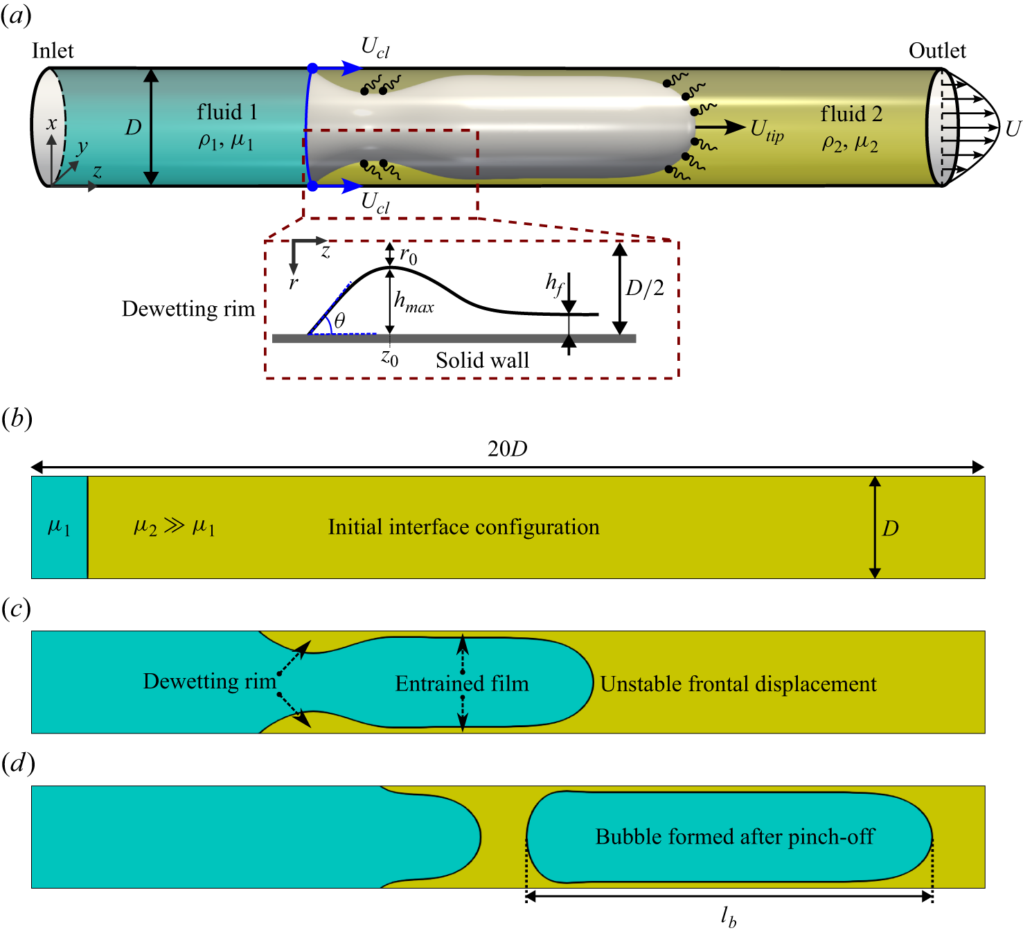


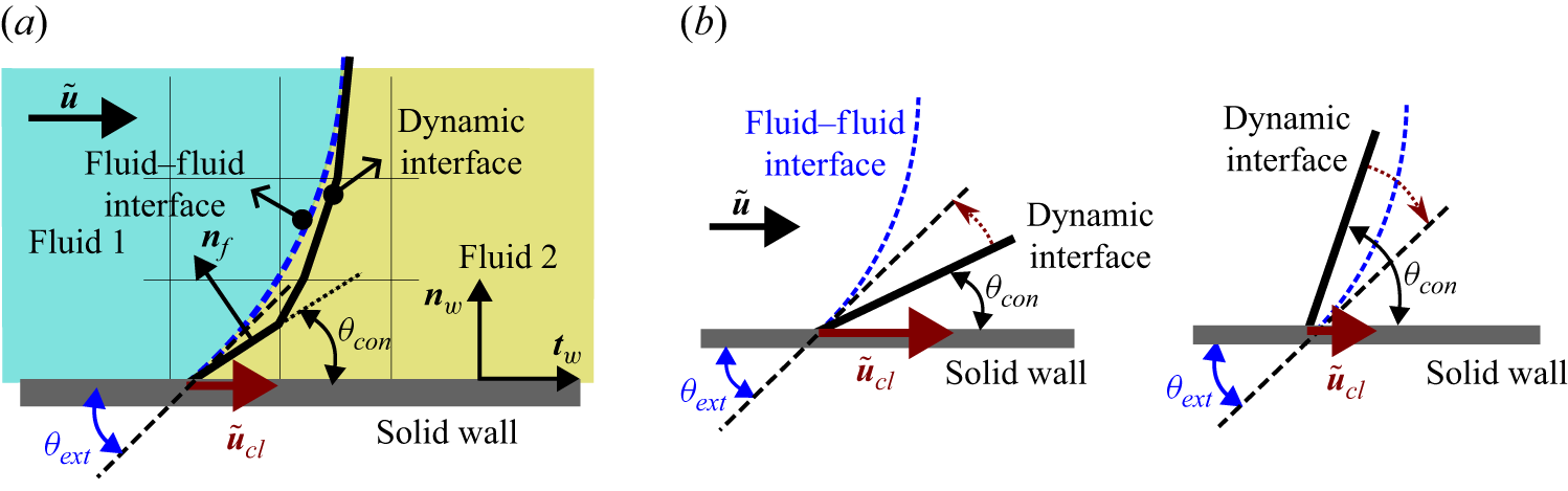


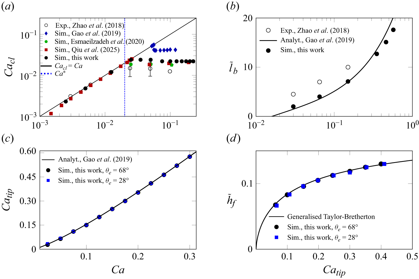


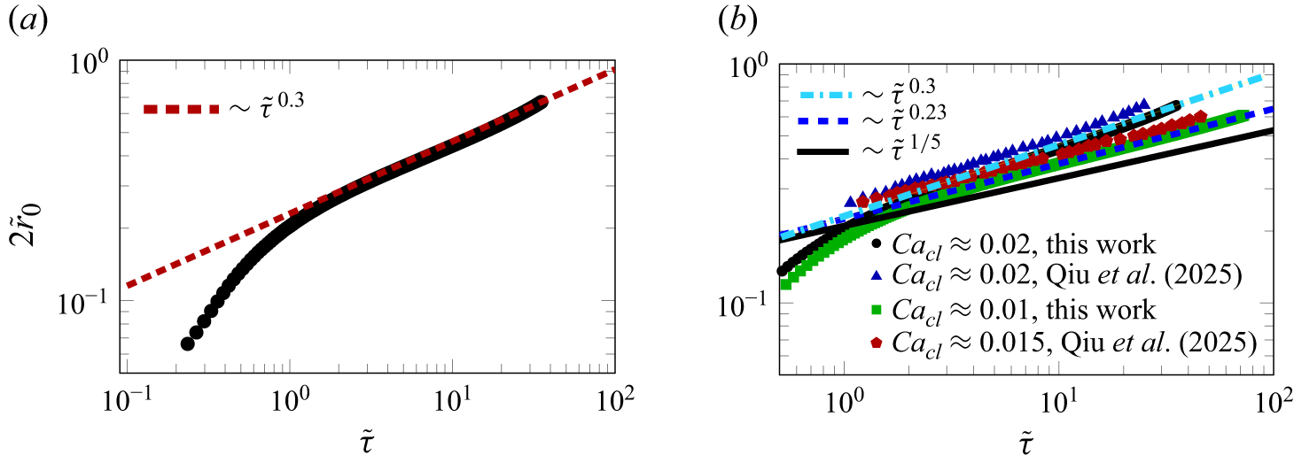


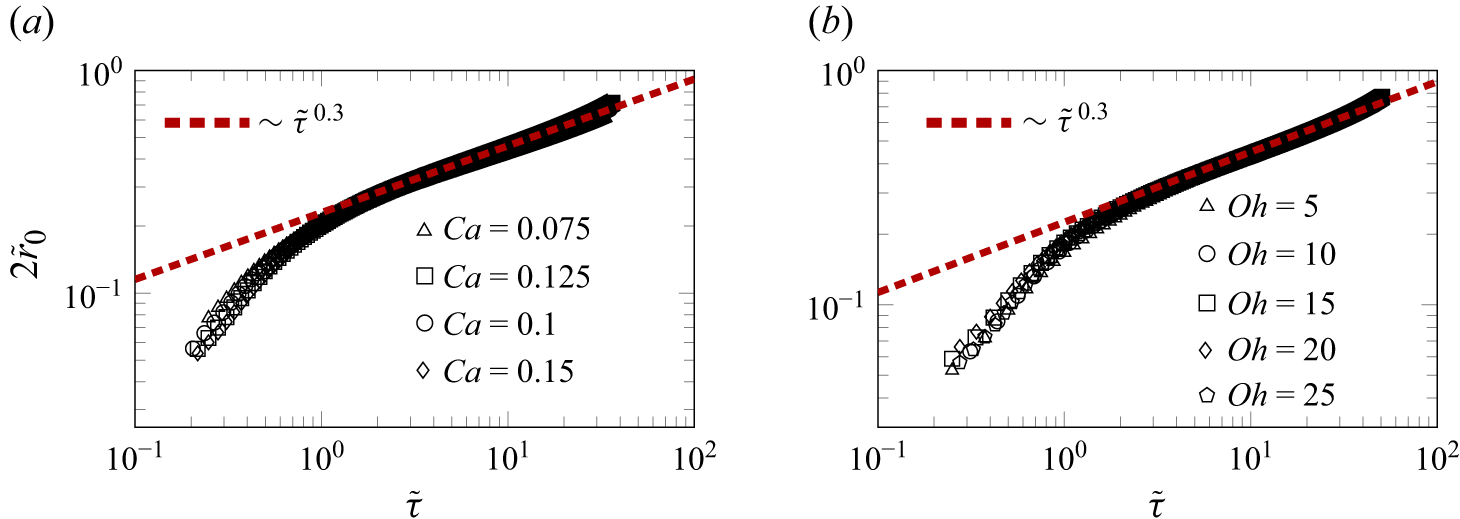


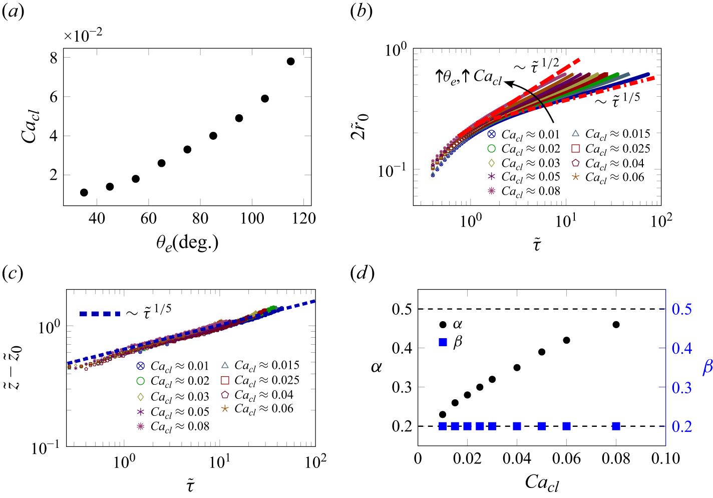


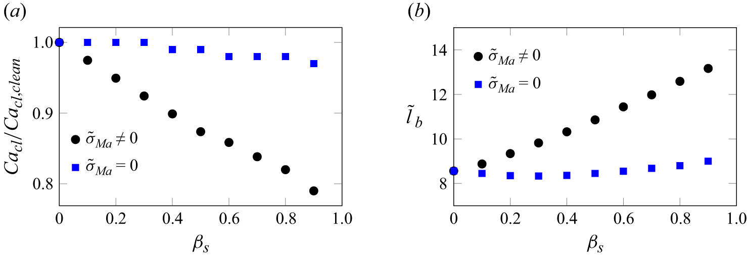


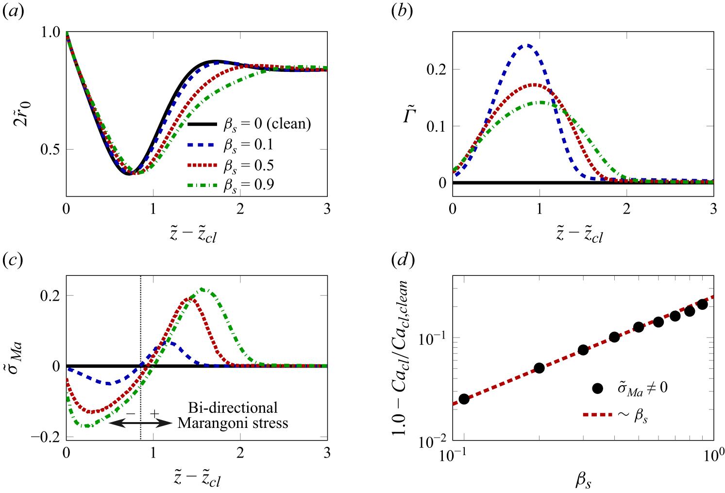


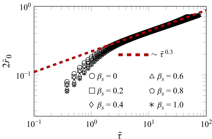


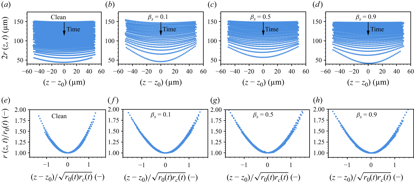


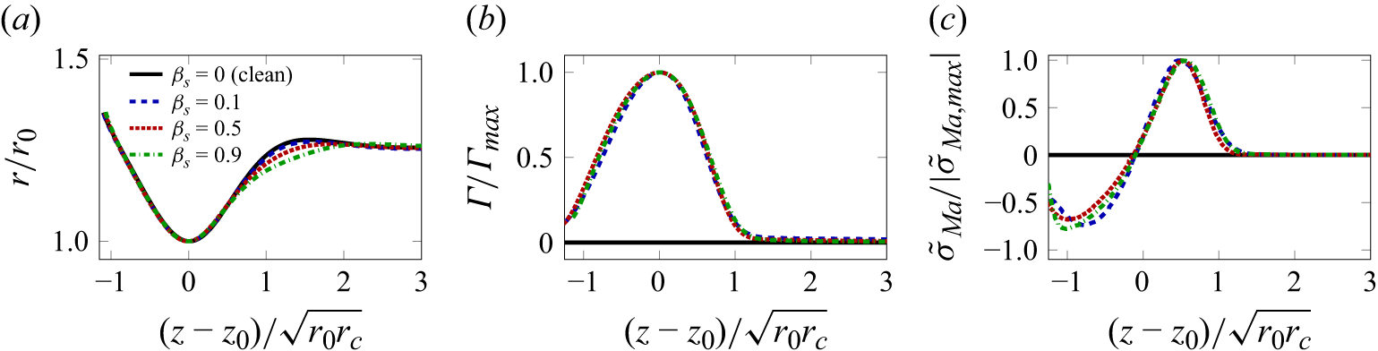


 Open access