


Stereotactic electroencephalography (SEEG) officially celebrated its 60th birthday this past year, but it might be better said to be experiencing a renaissance.Reference Bancaud and Dell 1 - Reference Cardinale, González-Martínez and Lo Russo 3 Originating with Bancaud and Talairach at Hôpital Sainte Anne in Paris, France, SEEG has since been in continuous use at a number of centres throughout the world, particularly in Europe.Reference Cardinale, González-Martínez and Lo Russo 3 , Reference Cardinale, Cossu and Castana 4 In Canada, chronic depth electrode recordings have been performed since the 1970s at McGill University and Université de Montréal,Reference Olivier, Gloor, Quesney and Andermann 5 , Reference Bouvier, Mercier, Hilaire, Giard, Labrecque and Beique 6 and in 1985 Olivier et alReference Olivier, Gloor, Andermann and Quesney 7 reported on the first 70 epilepsy patients investigated with SEEG at the Montreal Neurological Institute.Reference Olivier, Gloor, Andermann and Quesney 7 Despite this long history, SEEG was confined for many decades to a minority of epilepsy centres, in large part because of the expertise needed and the requirement for a two-stage surgical procedure (stereotactic angiography and electrode implantation).Reference Cardinale, González-Martínez and Lo Russo 3 , Reference Cardinale, Cossu and Castana 4 However, advances in multimodal imaging that have simplified and refined the procedure (and removed the requirement for stereotactic angiography) have fostered a rebirth of SEEG in North America and around the world.Reference Cardinale, González-Martínez and Lo Russo 3 , Reference Cardinale, Cossu and Castana 4
In this issue of the Journal, Joswig et alReference Joswig, Steven and Parrent 8 describe a near-complete shift from subdural recordings to SEEG over the past 4 years at the London Health Sciences Centre (LHSC). The authors describe the LHSC practice change as driven by shorter mean operative times, better patient tolerability and a lower risk profile.Reference Joswig, Steven and Parrent 8 Notwithstanding, they acknowledge a lack of high-quality evidence indicating superiority of any one technique for intracranial EEG (IEEG) monitoring, and affirm that selection of IEEG modality must currently be viewed as a state of equipoise.Reference Joswig, Steven and Parrent 8 It is important to keep in mind that the long history of epilepsy surgery excellence at LHSC, before the shift to SEEG, comprises 30 years of fruitful IEEG monitoring using subdural electrodes.Reference Joswig, Steven and Parrent 8 , Reference Pondal-Sordo, Diosy, Téllez-Zenteno, Sahjpaul and Wiebe 9 A future analysis of seizure outcomes comparing pre- and post-SEEG eras at LHSC will be extremely valuable to see the long-term impact of the transition in techniques on outcomes in patients receiving epilepsy surgery. Ideally, of course, other future studies will be designed to compare IEEG modalities, including randomized clinical trials.
Given the current absence of class I/II evidence, an expert consensus-based recommendation was recently published on the diagnostic utility of IEEG, including the strengths, limitations and risks of the various IEEG modalities, concluding that at present “neither the position of insisting on one particular IEEG modality in all cases nor rejecting its added value altogether in any scenario lends itself to scientific scrutiny”.Reference Jayakar, Gotman and Harvey 10
Subdural grid electrodes provide data from a two-dimensional cortical surface map well-suited for localizing neocortical epilepsies on the temporal, frontoparietal and occipital convexities.Reference Jayakar, Gotman and Harvey 10 Large areas of cortex can be covered, however, grid electrodes have limited precision for the definition of EEG patterns arising from deep generators, such as the amygdala, hippocampus, planum temporalis, insula and mesial frontal areas.Reference Jayakar, Gotman and Harvey 10 , Reference Taussig, Montavont and Isnard 11 Subdural strip electrodes are flexible and can be safely passed in the subdural space without direct visualization, allowing them to be placed at either the edges of a craniotomy or separately through a small burr hole, although it is sometimes impossible to reach certain areas because of bridging veins or adhesions, and in “blind” insertions, topographic imprecision is common.Reference Taussig, Montavont and Isnard 11 In addition to seizure onset localization, grid arrays offer the option to perform cortical functional mapping to define regions of eloquence.Reference Jayakar, Gotman and Harvey 10 , Reference Taussig, Montavont and Isnard 11 A significant difference between subdural grid and SEEG techniques is better patient tolerance of depth electrode implantations, with minimal headache and less frequent complications such as bleeding, raised intracranial pressure or cerebrospinal fluid leakage.Reference Cardinale, Cossu and Castana 4 , Reference Joswig, Steven and Parrent 8 , Reference Jayakar, Gotman and Harvey 10 Another issue arising in the choice of IEEG modalities is related to the hypothesis arrived at before implantation and the expertise of the epileptologist.Reference Joswig, Steven and Parrent 8 , Reference Kahane, Landré, Minotti, Francione and Ryvlin 12 Because a smaller area is potentially covered with depth electrodes, a more refined hypothesis may be required in SEEG, although typically several depth electrodes are implanted and what is lost in two-dimensional cortical surface coverage may be gained in three-dimensional cortical-subcortical-cortical coverage.Reference Cardinale, González-Martínez and Lo Russo 3 , Reference Jayakar, Gotman and Harvey 10 - Reference Kahane, Landré, Minotti, Francione and Ryvlin 12
Often forgotten in the discussions surrounding different IEEG modalities is the role of the clinical neurophysiologist interpreting the recordings. Setting aside the potential importance of analyzing broadband IEEG for infraslow activity and high-frequency oscillations,Reference Thompson, Krishnan and Gonzalez-Martinez 13 - Reference Jacobs, Zelmann and Jirsch 15 there exist uncertainties regarding IEEG interpretation in the standard clinical 0.5-70 Hz band-pass range—even with respect to defining ictal onset—and evidence to suggest poor interobserver agreement.Reference Jayakar, Gotman and Harvey 10 , Reference Singh, Sandy and Wiebe 16 , Reference Davis, Devries and Krieger 17 Furthermore, and particularly relevant for SEEG, basic questions surrounding the use of bipolar and referential montagesReference Zaveri, Duckrow and Spencer 18 and whether IEEG contacts record electrical potentials at a distance continue to be a source of debate.Reference Zaveri, Duckrow and Spencer 19 , Reference Wennberg 20 For example, it is often stated that IEEG electrode contacts do not “see” activity more than 5-10 mm away,Reference Jayakar, Gotman and Harvey 10 , Reference Zaveri, Duckrow and Spencer 19 but large cortical fields, such as those responsible for scalp EEG visible epileptiform discharges, produce volume conducted intracranial fields that can be recorded synchronously at multiple IEEG electrodes, which may be situated centimetres away from each other.Reference Wennberg 20 , Reference Wennberg and Lozano 21
Figure 1 highlights some of the particular benefits of SEEG as well as some of the interpretative issues just described. In this patient with post-traumatic epilepsy, SEEG revealed seizure onsets within the right inferior frontal sulcus, a localization that would have been impossible to identify using subdural electrodes overlying the cortical surface. The simultaneous recording from lateral and medial structures showed the onset of leftward head version and fencing posture to coincide with ictal propagation to the supplementary motor area, more than 30 s after seizure onset in the lateral frontal cortex, demonstrating the ability of SEEG to delineate the spatiotemporal organization of the epileptogenic zone, defined by its originators as the “site of the beginning and of the primary organization” of focal onset seizures.Reference Kahane, Landré, Minotti, Francione and Ryvlin 12 , Reference Munari and Bancaud 22 In this case, SEEG was an ideal IEEG modality, and examination of the field of distribution of the initial ictal spike discharges afforded a general idea about the extent of the lateral frontal cortex involved in ictal onsets, sufficient to plan a superolateral frontal lobe resection sparing anterior cingulate cortex and supplementary motor area. Nevertheless, it must be admitted that a subdural grid over the lateral frontal convexity would have better demonstrated the surface neocortical extent of the area of ictal onset, and an interhemispheric subdural strip might have provided similar information about the timing of propagation to the supplementary motor area.
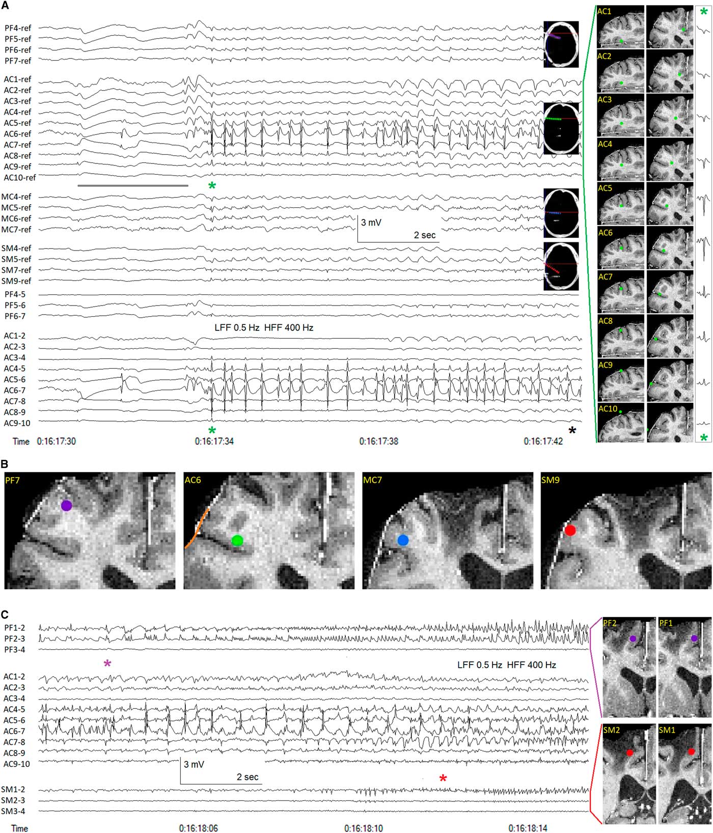
Figure 1 Stereotactic EEG (SEEG) recording in a patient with frontal lobe epilepsy. (A) Unilateral right hemispheric implantation of seven multi-contact SEEG electrodes. The four anterior-most electrodes are shown, contacts 1 medial, contacts 10 lateral: PF=prefrontal (anterior to traumatic encephalomalacia), purple; AC=anterior cingulate, green; MC=mid cingulate, blue; SM=supplementary motor area, red. Subgaleal reference electrode. Sampling frequency=1 kHz. Anterior cingulate electrode SEEG recording depicted in both referential and bipolar montages. Anterior cingulate electrode contact positions shown in axial and coronal planes, reconstructed from co-registration of post-implantation CT and pre-implantation MR images. Earliest ictal changes probably marked by slow baseline shifts (and associated low amplitude spikes, electronegative at AC7 and electropositive at AC6), the slow shifts attenuated by the 0.5 Hz low-frequency filter (LFF), yet apparent at all contacts of the AC electrode, inverting in polarity across the cortical mantle (compare with the anatomical positions of contacts AC7 and AC6), the slow shift extending anteriorly to the PF electrode, but not to the more posterior MC and SM electrodes (grey line). The initial rhythmic ictal activity (green asterisk) occurred as repetitive spike discharges of maximal (electropositive) amplitude at AC6>AC5>>AC4, the spike potentials appearing electronegative on the cortical surface (AC7-9). The relatively high amplitude of the electropositive spike field at AC6 and AC5 may indicate that these two contacts are surrounded by grey matter in the axial plane (see axial images of AC6 and AC7 contacts). The volume conducted intracranial field of the ictal spike discharges can be seen to be strongest surrounding the AC electrode, extending anteriorly with low amplitude to the PF electrode and posteriorly with lower amplitude to the MC and SM electrodes. The medial-lateral amplitude decrement of the volume conducted field of the initial ictal spike, recorded at each contact of the AC electrode, is shown at the far right, the amplitude of the positive field decreasing with distance through white matter and into the anterior cingulate cortex, the amplitude of the surface negative field similarly decreasing with distance from the cortical source located in the inferior frontal sulcus. Clinical seizure onset (black asterisk) marked by tonic stiffening occurred nine seconds after the initial rhythmic ictal SEEG changes (green asterisk). (B) Electrode contact positions anterior/superior (PF7) and posterior (MC7, SM9) to the location of seizure onset (AC6). One cannot know with certainty from the SEEG recordings the extent of involvement of the crowns of the middle and inferior frontal gyri (orange line) above and below the inferior frontal sulcus surrounding the entry point of the AC electrode. (C) Continuation of seizure, ~20 seconds later. Bipolar montage showing medial contacts of PF and SM electrodes as well as all AC electrode contacts. Anteromedial ictal propagation evident at contacts PF1, PF2 (purple asterisk). Subsequent propagation to supplementary motor area (SM1) associated with commencement of leftward head version and tonic fencing posture (red asterisk). HFF=high-frequency filter.
Irrespective the favoured modality of the different epilepsy centres across the country, the rebirth of SEEG is a welcome event and its adoption by LHSC an important step in expanding Canadian expertise with this time-honoured technique. As a most valuable member of the IEEG family, increased experience with SEEG and its interpretation are sure to continue Canada’s long history of excellence in epilepsy surgery and EEG.
Acknowledgements
Taufik Valiante and Suneil Kalia performed the intracranial electrode implantations that enabled acquisition of the SEEG data shown in the figure. Victoria Barkley performed the electrode position reconstructions.
DISCLOSURES
The authors have nothing to disclose.

