

I. Introduction
Orthogonal frequency-division multiplexing (OFDM) has become a widely accepted technique for high data rate wireless access systems. Indeed, owing to its inherent robustness to multipath propagation, OFDM has become the modulation choice for many communication systems [Reference Yong Soo Cho, Kim and Kang1–Reference Molisch3].
A very promising technical approach for future wireless communication systems is to combine OFDM and direct-conversion receivers (DCRs). The DCR is a promising approach as it provides a low-cost and low-power receiver implementation over the traditional superheterodyne receivers [Reference Tarighat, Bagheri and Sayed4,Reference Xing, Shen and Liu5]. However, DCRs front-ends are sensitive to component imperfections due to manufacturing non-uniformity, resulting to radio frequency (RF) impairments such as in-phase and quadrature (I/Q) imbalances and the carrier frequency offset (CFO) [Reference Tarighat, Bagheri and Sayed4–Reference Lin, Zhu and Yamashita9].
Since RF impairments are unavoidable in low-cost and low-power DCRs front-ends, then, to obtain better performance for such communication systems, efficient estimation and compensation for the RF impairments is crucial [Reference Xing, Shen and Liu5, Reference Sung and Chao Chao10]. CFO and I/Q mismatch seriously degrade the system performance, and their estimation and compensation are generally difficult as they are entangled in the received signal. I/Q imbalance results in a mirroring effect while CFO destroys the orthogonality among the subcarriers in OFDM systems and gives rise to inter-carrier interferences (ICI) [Reference Xing, Shen and Liu5, Reference Park, Lee and Park7, Reference Nee and Prasad11].
In the literature, several algorithms for estimation of CFO, frequency-selective channel and/or I/Q imbalance have been proposed (see [Reference Tarighat, Bagheri and Sayed4, Reference Xing, Shen and Liu5, Reference Park, Lee and Park7–Reference Sung and Chao Chao10, Reference Manasseh, Ohno and Nakamoto12–Reference Morelli and Mengali14] and references therein). Most of the existing schemes are based on the estimation and compensation for individual I/Q imbalance and CFO by using specific preambles [Reference Tarighat, Bagheri and Sayed4, Reference Manasseh, Ohno and Nakamoto12–Reference Morelli and Mengali14]. In [Reference Manasseh, Ohno and Nakamoto12–Reference Morelli and Mengali14], CFO estimation schemes using the preamble (a.k.a training symbols) with repeated pattern have been proposed. The preambles in [Reference Manasseh, Ohno and Nakamoto12–Reference Morelli and Mengali14] provide promising CFO performance in the absence of I/Q imbalance. However, these preamble structures are not efficient for CFO estimation in the presence of I/Q imbalance and may not provide simple and accurate estimations of I/Q imbalance.
In [Reference Tarighat, Bagheri and Sayed4], a special preamble pattern to enable accurate estimation of I/Q imbalance is proposed. With the special preamble pattern in [Reference Tarighat, Bagheri and Sayed4], I/Q imbalance is efficiently estimated and compensated, however, the channel estimate mean-squared error (MSE) is poor since channel is estimated by the preamble sequences allocated on one side of the active subcarrier band, whereas subcarriers on the other side are nulled. In [Reference Park, Lee and Park7–Reference Lin, Zhu and Yamashita9, Reference Tubbax15], several joint estimation schemes have been proposed to estimate I/Q imbalance as well as CFO. In [Reference Tubbax15], a low-complexity joint estimation method for the preamble of repeated pattern in IEEE 802.11a has been proposed; however, the algorithm in [Reference Tubbax15] suffers from serious error propagation problem especially for large I/Q imbalances. Furthermore, the I/Q imbalance estimation cannot work in low CFO environment.
In [Reference Park, Lee and Park7, Reference Luo, Keusgen and Kortke8] preamble structures for joint estimation of CFO and I/Q imbalance by using several repetitive symbols have been proposed. The method can efficiently estimate and compensate for these impairments; however, the overhead is huge as the method requires several repeated symbols to perfectly compensate for the CFO.
Also, in [Reference Lin, Zhu and Yamashita9], periodic pilot and an associated compensation method is proposed. The scheme in [Reference Lin, Zhu and Yamashita9] simultaneously estimates the CFO and coefficients of I/Q imbalance, in closed forms based on the linear least-squares algorithm. However, similar to [Reference Park, Lee and Park7], the number of required pilot symbols is large.
This paper proposes a preamble structure for estimating the frequency-selective channel, CFO and I/Q imbalance. We utilize a low-complexity algorithm based on adaptive Markov chain Monte Carlo (AMCM) optimization techniques to design preamble sequences that minimizes the channel estimate MSE as well as the the peak power of the training signals while suppressing the effect of I/Q imbalance. The proposed AMCMC algorithm selects the position of training symbols by deactivating some of the active subcarriers (i.e., some active subcarriers are nulled). Unlike [Reference Tarighat, Bagheri and Sayed4], where special pilot patterns are obtained by setting active subcarriers on the lower or upper side of the active band to zero, AMCMC scheme selects the position of training symbols to obtain better channel estimate MSE.
Unlike pilot symbols assisted transmission, where equal-spaced equal-powered pilot symbols are not necessarily optimal [Reference Ohno, Manasseh and Nakamoto16–Reference Hamilton, Ma, Kleider and Baxley19] for channel estimation, in [Reference Ohno, Manasseh and Nakamoto16] it is demonstrated that, the MSE performance of the channel estimator using optimized preamble is comparable to that of the equal-powered preamble. The proposed I/Q imbalance estimator requires some modifications in the structure of the preamble; thus we will consider both optimized preambles as well as equal-powered preambles.
Furthermore, in preamble power optimization, it is difficult to adopt the analytical power optimization schemes in [Reference Huang, Ghogho and Freear18, Reference Hamilton, Ma, Kleider and Baxley19] since these algorithms are applicable only when the length of the channel (channel delay profile) L, is equivalent to the number of optimized subcarriers. For the preamble case there are many subcarriers than the number of channel taps L. Thus, we will adopt the design in [Reference Ohno, Manasseh and Nakamoto16] for preamble power optimization.
For the two schemes, i.e., equal-powered and the optimized power preamble, we utilize our proposed AMCMC algorithm for selecting the placement and phase information of the preambles. Simulation results are provided to substantiate the effectiveness of the proposed designs. Finally based on the results, we discuss how to select the most appropriate preamble structure out of the two designs by considering a tradeoff between performance and implementation complexity.
The following notations are used in the description of the system. The superscripts *, T, and
 ${\cal H}$
represent conjugate, transpose, and the conjugate transpose (Hermitian), respectively. The operator ⊗, denotes the convolution operation. Other operators that are used will be defined whenever used.
${\cal H}$
represent conjugate, transpose, and the conjugate transpose (Hermitian), respectively. The operator ⊗, denotes the convolution operation. Other operators that are used will be defined whenever used.
II. System Model
We consider a baseband model of the wireless OFDM system. Figure 1 depicts a block diagram of an OFDM system under various channel impairments. The frequency-domain and time-domain vectors are represented by the upper and lower case letters, respectively, whereas the superscript (·)
T
and
 $\lpar{\cdot}\rpar ^{\cal H}$
denote the transpose and Hermitian transpose, respectively. At the transmitter, the frequency-domain representation of the mth transmitted OFDM symbol with N number of subcarriers is given by a vector
X
m
= [X
m,0, X
m,1,…,X
m,N−1]
T
, and the corresponding time-domain signal is given by
$\lpar{\cdot}\rpar ^{\cal H}$
denote the transpose and Hermitian transpose, respectively. At the transmitter, the frequency-domain representation of the mth transmitted OFDM symbol with N number of subcarriers is given by a vector
X
m
= [X
m,0, X
m,1,…,X
m,N−1]
T
, and the corresponding time-domain signal is given by
 ${\bi x}_{m}={1 \over N}{\bi F}^{\cal H}{\bi X}_m$
, where
F
is an N × N Fast Fourier Transform (FFT) matrix with (k + 1, n + 1)th entry given by
${\bi x}_{m}={1 \over N}{\bi F}^{\cal H}{\bi X}_m$
, where
F
is an N × N Fast Fourier Transform (FFT) matrix with (k + 1, n + 1)th entry given by
 $\lsqb {\bi F}\rsqb _{k\comma n} = e^{j2\pi kn \over N}$
and
x
m
= [x
m,0, x
m,1,…,x
m,n
]
T
.
$\lsqb {\bi F}\rsqb _{k\comma n} = e^{j2\pi kn \over N}$
and
x
m
= [x
m,0, x
m,1,…,x
m,n
]
T
.
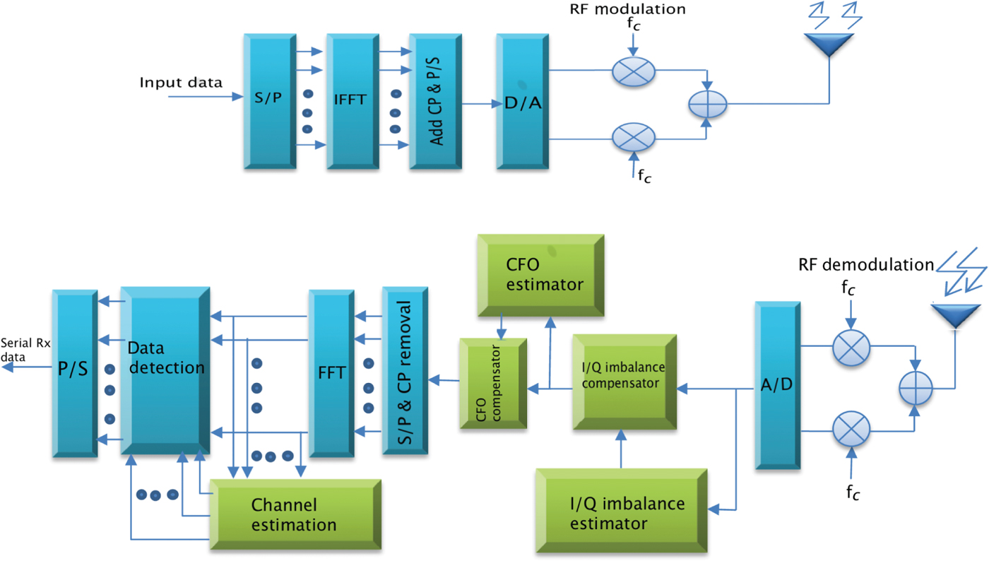
Fig. 1. Block diagram of an OFDM system.
The discrete channel impulse response is given by
h
= [h
0, …, h
L−1]
T
, where L is the number of channel paths. The frequency-domain channel impulse response is
H
=
F
L
h
with
F
L
= [
f
0,…,
f
L−1] representing the N rows and the first L columns of the matrix
F
. The CFO between the transmitter and receiver is normalized by the subcarrier spacing, and the normalized CFO is denoted by ε. Let f
c
and f
c
′ denote the transmitter and receiver carrier frequencies respectively. The frequency offset is given by f
o
= f
c
− f
c
′. Thus, for a given subcarrier spacing Δ f, the normalized frequency offset
 $\epsilon={f_{o} \over \Delta f}$
. It should be noted that, ε consists of the integer and (fraction) residual part. The integer part can easily be compensated by cyclic shift of the received signal. Moreover, the integer part does not destroy the orthogonality among frequency subcarriers, thus ICI does not occur. In this paper, we only consider the residual CFO, which may cause ICI.
$\epsilon={f_{o} \over \Delta f}$
. It should be noted that, ε consists of the integer and (fraction) residual part. The integer part can easily be compensated by cyclic shift of the received signal. Moreover, the integer part does not destroy the orthogonality among frequency subcarriers, thus ICI does not occur. In this paper, we only consider the residual CFO, which may cause ICI.
At the receiver, after discarding the cyclic prefix (CP), received signals with CFO before being distorted by I/Q imbalance caused by the analog processing can be described as [Reference Manasseh, Ohno and Nakamoto12]
 $${\bi y}_{m}= {\bi {D}}\lpar \epsilon\rpar {\bi {F}}^{\cal H}{\bi {D}}\lpar {\bi {X}}_{m}\rpar {\bi {H}}+ {\bi {v}}_{m}\comma \;$$
where
 ${\bi D}\lpar \epsilon\rpar ={\rm diag}\left(1\comma \; e^{j 2\pi\epsilon{1\over N}}\comma \; \ldots\comma \; e^{j2\pi\epsilon {N-1 \over N}}\right)$
describes the phase-rotating effect caused by frequency offset on each time domain and
D
(
X
m
) is a diagonal matrix of the vector
X
m
, and
v
m
is the independent identically distributed (i.i.d.) white Gaussian noise. For a practical OFDM system where some of the subcarriers at the edge are nulled, given N
a
as a number of active subcarriers and
X
k,a
as a transmitted OFDM symbol in the frequency domain at the active subcarriers, then the received signal can be expressed as
${\bi D}\lpar \epsilon\rpar ={\rm diag}\left(1\comma \; e^{j 2\pi\epsilon{1\over N}}\comma \; \ldots\comma \; e^{j2\pi\epsilon {N-1 \over N}}\right)$
describes the phase-rotating effect caused by frequency offset on each time domain and
D
(
X
m
) is a diagonal matrix of the vector
X
m
, and
v
m
is the independent identically distributed (i.i.d.) white Gaussian noise. For a practical OFDM system where some of the subcarriers at the edge are nulled, given N
a
as a number of active subcarriers and
X
k,a
as a transmitted OFDM symbol in the frequency domain at the active subcarriers, then the received signal can be expressed as
 $${\bi y}_{m} = {\bi D}\lpar \epsilon\rpar {\bi F}^{\cal H}_{a}{\bi D}\lpar {\bi X}_{m\comma a}\rpar {\bi F}_{L\comma a}{\bi h}+ {\bi v}_{m}\comma \;$$
where F a and F L,a are N a × N and N a × L sub-matrices of F and F L , respectively, which corresponds to the active subcarriers.
Similarly, the second received OFDM symbol for the transmitted OFDM symbol X m+1,a can be expressed as
 $${\bi y}_{m+1}= e^{j\beta\epsilon} {\bi D}\lpar \epsilon\rpar {\bi F}_{a}^{\cal H}{\bi D}\lpar {\bi X}_{m+1\comma a}\rpar {\bi F}_{L\comma a}{\bi h}+ {\bi v}_{m+1}\comma \;$$
where
 $\beta={2\pi\lpar N+N_{cp}\rpar \over{N}}$
is one OFDM symbol duration (including CP of length N
cp
).
$\beta={2\pi\lpar N+N_{cp}\rpar \over{N}}$
is one OFDM symbol duration (including CP of length N
cp
).
Stacking two successive received OFDM preambles leads to[Reference Manasseh, Ohno and Nakamoto12]
 $$\tilde{\bi y}_{m} = \left[\matrix{{\bi y}_{m}\cr {\bi y}_{m+1}}\right]=\left[\matrix{{\bi D}\lpar \epsilon\rpar {\bi F}_{a}^{\cal H}{\bi D}\lpar {\bi X}_{m\comma a}\rpar \cr e^{j\beta\epsilon} {\bi D}\lpar \epsilon\rpar {\bi F}_{a}^{\cal H}{\bi D}\lpar {\bi X}_{m +1\comma a}\rpar }\right]{\bi F}_{L\comma a}{\bi h} + \tilde{\bi v}_{m}$$
 $$= {\bi A}{\bi h} + \tilde{\bf v}_{m}\comma \;$$
where
 $\tilde{{\bi v}}_{m}=\lsqb {\bi v}^{T}_{m} {\bi v}^{T}_{m+1}\rsqb $
. The maximum-likelihood (ML) estimate of the channel
h
and CFO ε are obtained by minimizing
$\tilde{{\bi v}}_{m}=\lsqb {\bi v}^{T}_{m} {\bi v}^{T}_{m+1}\rsqb $
. The maximum-likelihood (ML) estimate of the channel
h
and CFO ε are obtained by minimizing
 $\Vert \tilde{{\bi y}}_{m} - {\bi A}{\bi h} \Vert^{2}.$
The ML estimate of
h
is given by
$\Vert \tilde{{\bi y}}_{m} - {\bi A}{\bi h} \Vert^{2}.$
The ML estimate of
h
is given by
 $\hat{{\bf h}}=\left[{\bf A}^{\cal H}{\bi A}\right]^{-1}{\bi A}^{\cal H}\tilde{\bi y}_{m}$
, and the channel estimate MSE is given by
$\hat{{\bf h}}=\left[{\bf A}^{\cal H}{\bi A}\right]^{-1}{\bi A}^{\cal H}\tilde{\bi y}_{m}$
, and the channel estimate MSE is given by
 $${\bf \eta}=E\lcub \Vert \hat{{\bi h}} -{\bi h}\Vert^{2}\rcub =\sigma^{2}_{v}\, {\rm trace} \left[\left({\bi A}^{\cal H}{\bi A} \right)^{-1}\right].$$
For X m = X m+1, let us define a matrix
 $${\bf \Lambda}_{m}= D\lpar {\bf X}_{m}\rpar D^{\cal H}\lpar {\bf X}_{m}\rpar =diag\lpar \lambda_1\comma \; \ldots\comma \; \lambda_N\rpar \comma \;$$
where the vector λ = [λ, …, λ N ] denote the power distribution to the preambles. For a given set of active subcarriers, the channel estimate MSE caused by Gaussian noise can be written as
 $${\bf \eta}={\sigma^{2}_{v}\over {2}} {\rm trace}\left[{\bi F}_{L\comma a}^{\cal H}\left({\bi F}^{\cal H}_{L\comma a} \bf \Lambda_{{\bi m}\comma {\bi a}} {\bi F}_{{\bi L}\comma {\bi a}} \right)^{-1}{\bi F}_{{\bi L}\comma {\bi a}}\right]\comma \;$$
where σ2 v is the variance of the white Gaussian noise.
A) I/Q imbalance parameter estimation
The received time-domain signal distorted by I/Q imbalance can be modeled as [Reference Tarighat, Bagheri and Sayed4]
 $${\bi r}_{m}=\mu {\bi y}_{m} + \nu{\bi y}^{\ast}_{m}\comma \;$$
where the notation {}* represents the conjugate of {}.
The distortion parameters I and Q are related to the amplitude and phase imbalances of the I and Q branches in the RF/analog demodulation process as
 $$\eqalign{\mu & = \cos\lpar \theta/2\rpar +j\alpha\sin\lpar \theta/2\rpar \comma \; \cr \nu & = \alpha\cos\lpar \theta/2\rpar -j\sin\lpar \theta/2\rpar \comma \; }$$
where θ and α are the phase and amplitude between the I and Q branches, respectively. The phase imbalance is any phase deviation from the ideal 90° between the I and Q branches. The amplitude imbalance is defined as
 $$\alpha ={{a_{I}-a_{Q}}\over{a_{I} + a_{Q}}}.$$
Note that Equation (9) implies that the signal is first distorted by CFO and then by I/Q imbalance. To formulate reasonable constraints for the preamble design, we consider received signals without phase errors, i.e., when ε = 0. Frequency-domain representation of the received signal y m without phase errors can be written as [Reference Manasseh, Ohno and Nakamoto12]
 $${\bf Y}_{m}= {\bf D}\lpar {\bf X}_{m}\rpar {\bf H}+ {\bf w}_{m}\comma \;$$
where w m is the equivalent white noise in frequency domain. To estimate the interference caused by the I/Q imbalance, the preambles should be designed in such away that the received signals at subcarrier k is not affected by the corresponding mirror signals at subcarrier N − k + 2. The easiest approach is to design the preamble symbols with some null subcarriers in the active band such that, the product of the non-null training tones and its corresponding mirror tones is zero. That is, X(k)X #(N − k + 2) = 0. Thus, for the received preamble signals, the accuracy of the I/Q imbalance estimation is closely related to the term
 $$\gamma=Y_{m}\lpar k\rpar Y^{\#}_{m}\lpar N-k+2\rpar \comma \;$$
which represents the product of the received signal and its received mirror signal. Here, Y # m is the Discrete Fourier Transform (DFT) of y * m . Note that, the DFT of the complex conjugate of a sequence x is related to the DFT of the original sequence X through a mirrored relation (for 1 ≤ n ≤ N and 1 ≤ k ≤ N) [Reference Tarighat, Bagheri and Sayed4], i.e.,
 $$\eqalign{& x\lpar n\rpar \mathop{DFT}\limits_{\longrightarrow} X\lpar k\rpar \comma \; \cr & x^{*}\lpar n\rpar \mathop{DFT}\limits_{\longrightarrow} X^{\#}\lpar N-k+2\rpar .}$$
For parameter estimation based on a preamble, the symbol X k can be designed such that γ is small for arbitrary distortion due to channel and phase errors. It is clear that, γ is minimum if a preamble is selected such that X(k)X #(N − k + 2) + 0, which imply that D( X m ) D( X # m ) = 0, and thereby
 $${\bf \Lambda}_{m}{\bf \Lambda}^{\#}_{m}=0.$$
The easiest way of meeting the condition in (15) is to set the active subcarriers in the lower or upper bands of the central DC subcarrier to zero and allocate power to the subcarriers on one sideband which is not nulled as in [Reference Tarighat, Bagheri and Sayed4]. However, this will lead to poor estimate of the channel since channel is only estimated by either upper or lower subcarriers. To ensure better MSE performance, both training allocation and power distribution need to be careful considered.
III. Preamble Design
In this section, we propose a preamble design for estimation of frequency-selective channel, CFO and receiver I/Q imbalance. We consider OFDM signals over peak-limited channels. Peak-limited channel provides more design challenges as it imposes the peak power constraints to the transmitted signals. Thus, the main objective is to investigate practical low-complexity preamble designs for estimation and compensation for the nonlinear distortions in OFDM systems over peak-power-limited channels.
We utilize some criteria to design preamble that minimizes the channel estimate MSE while suppressing the interference replica caused by the I/Q imbalances. To estimate the residual CFO, we adopt an ML estimator in [Reference Manasseh, Ohno and Nakamoto12] that utilizes two consecutive OFDM preambles. To ensure that the designed preamble capture the negative effects of peak-limitation, we select phase information to the preamble sequence to reduce the peak amplitude of the time-domain signal.
We define a set active subcarriers as
 ${\cal K}_a$
. To suppress the interference replica, our proposed design set to zero some of the active subcarriers. Assume
${\cal K}_a$
. To suppress the interference replica, our proposed design set to zero some of the active subcarriers. Assume
 ${\cal K}_p$
to be a non-zero selected set of subcarriers from
${\cal K}_p$
to be a non-zero selected set of subcarriers from
 ${\cal K}_a$
. We denote the number of non-zero preamble symbol by
${\cal K}_a$
. We denote the number of non-zero preamble symbol by
 $N_p=\vert{\cal K}_p \vert$
, where the notation, | · | denotes cardinality of a set. For a given energy to be utilized for channel estimation, we normalize the sum of preamble power such that
$N_p=\vert{\cal K}_p \vert$
, where the notation, | · | denotes cardinality of a set. For a given energy to be utilized for channel estimation, we normalize the sum of preamble power such that
 $$\sum_{k=1}^{N_p} \lambda_k = 1.$$
We define a vector
 $$\lambda=\lsqb \lambda_1\comma \; \ldots\comma \; \lambda_{N_p}\rsqb ^T.$$
For equal-powered preamble where
 $\lambda_1=\lambda_2=\cdot\cdot\cdot=\lambda_{N_{p}}=1/N_{p}$
, our problem is to determine the position of the non-zero preamble
$\lambda_1=\lambda_2=\cdot\cdot\cdot=\lambda_{N_{p}}=1/N_{p}$
, our problem is to determine the position of the non-zero preamble
 ${\cal K}_p$
, that minimizes η in (8) under the constraints (15). While for unequal-powered preambles, the task involves optimization of power as well as the selection of the position of the non-zero preamble to minimize η. Note that (15) is a constraint to ensure the interference replica caused by I/Q imbalance is suppressed.
${\cal K}_p$
, that minimizes η in (8) under the constraints (15). While for unequal-powered preambles, the task involves optimization of power as well as the selection of the position of the non-zero preamble to minimize η. Note that (15) is a constraint to ensure the interference replica caused by I/Q imbalance is suppressed.
Let us represent the training symbol with phase information as
 $${\bf X}_{m\comma p}\lpar \phi_{p}\rpar = \left[X_{1}\, e^{j\phi_{1} }\comma \; X_{2}\, e^{j \phi_{2} }\comma \; \ldots\comma \; X_{N_{p}}\, e^{j \phi_{N_{p}}} \right]\comma \;$$
where
X
m,p
and ϕ
p
are the amplitudes and phase information of the training symbol corresponding to the subcarrier set
 ${\cal K}_p$
. To obtain the approximate of the continuous time signal, we oversample the training signal at a sampling rate
${\cal K}_p$
. To obtain the approximate of the continuous time signal, we oversample the training signal at a sampling rate
 ${\cal L}$
. The signal obtained by
${\cal L}$
. The signal obtained by
 ${\cal L}N$
-points IFFT can be expressed as
${\cal L}N$
-points IFFT can be expressed as
 $${\bi x}\lpar \phi\rpar ={\bf \Gamma}_{p} {\bf X}_{m\comma p}\lpar \phi_{p}\rpar \comma \;$$
where Γ
p
is an
 ${\cal L} N \times N_p$
DFT sub-matrix of Γ with
${\cal L} N \times N_p$
DFT sub-matrix of Γ with
 $$\Gamma_{t\comma k}={1 \over {\sqrt{{\cal L} N}}}e^{{j}{2\pi k t \over {\cal L}N}}\comma \; \quad t \in \lsqb 0\comma \; {\cal L}N - 1\rsqb \comma \; \quad k \in \lsqb 0\comma \; N-1\rsqb .$$
The PAPR of the transmitted signal in (19) is defined as
 $$PAPR={\Vert x\lpar \phi\rpar \Vert_{\infty}^2 \over E \lcub \vert x \lpar \phi\rpar \vert^2\rcub }\comma \;$$
where
 $E \lcub \vert x \vert^2 \rcub $
is the average power of the signal and E{·} denotes expectation operation. Note that,
$E \lcub \vert x \vert^2 \rcub $
is the average power of the signal and E{·} denotes expectation operation. Note that,
 $\Vert x \Vert_{\infty}$
is the infinity norm of the time-domain signals.
$\Vert x \Vert_{\infty}$
is the infinity norm of the time-domain signals.
The channel estimate MSE does not depend on the phase of the training symbols. Thus, for equal-powered preamble, to minimize the channel estimate MSE, all we need is to determine the optimal set of
 ${\cal K}_p$
. However, to minimize PAPR requires careful selection of phase information of the training symbol. The optimization problem under these constraints can be stated as
${\cal K}_p$
. However, to minimize PAPR requires careful selection of phase information of the training symbol. The optimization problem under these constraints can be stated as
 $$\eqalign {& \mathop{\hbox{minimize}}\limits_{\lambda\comma {\cal K}_p}\quad \hbox{trace}\left[{\bf F}^{\cal H}_{L\comma a} \left({1\over {\sigma_v^2}} {\bf F}_{L\comma p}^{\cal H}\Lambda_{m\comma p}{\bf F}_{L\comma p} \right)^{-1}{\bf F}_{L\comma a} \right]\cr & \hbox{subject to} \quad \left[1\comma \; \ldots\comma \; 1 \right]{\bf \lambda} \leq 1\comma \; \quad {\bf \lambda} \succeq 0\comma \; \cr & \quad \quad \quad \quad \quad{\bf \Lambda}_{m} {\bf \Lambda}^{\#}_{m}=0\comma \; \cr & \quad \quad \quad \quad \quad \min_{\phi_{p} \in {0 \comma \pi}} \Vert {\bf x}\lpar \phi_{p}\rpar \Vert_{\infty} \le \Upsilon.}$$
where
 ${\bf \Lambda}_{m\comma p}={\rm diag}\lpar \lambda_{1}\comma \; \ldots\comma \; \lambda_{N_{p}}\rpar \comma \; {\bf F}_{L\comma p}$
is an N
p
× L sub-matrix of
F
corresponding to
${\bf \Lambda}_{m\comma p}={\rm diag}\lpar \lambda_{1}\comma \; \ldots\comma \; \lambda_{N_{p}}\rpar \comma \; {\bf F}_{L\comma p}$
is an N
p
× L sub-matrix of
F
corresponding to
 ${\cal K}_p$
.
${\cal K}_p$
.
Note that (15) is a constraint to ensure the interference replica caused by I/Q imbalance is suppressed, i.e.,
 $$\lambda\lpar k\rpar \lambda^{\ast}\lpar N-k+2\rpar =0.$$
The problem in (22) above is a non-convex optimization problem and cannot be solved easily. However, we can split it in two parts. First, subcarrier selection to minimize the channel estimate MSE under white Gaussian noise, then design of phase information with a potential of reducing the PAPR.
To design the special training sequences, we need to set some subcarriers to zero as proposed in [Reference Tarighat, Bagheri and Sayed4]. Thus, to obtain a suitable preamble sequence, we employ the AMCMC method for selecting subcarriers that minimizes the channel estimate MSE and eliminate the interference replica. The PAPR of the designed preamble can be minimized by careful selection of phase information to the designed preamble. AMCMC algorithm is also adopted in the selection of phase information.
A) Subcarrier selection
The objective is to select a preamble sequence, such that the channel estimate MSE is minimized. Our training sequence design can be formulated as a combinatorial optimization problem as
 $${\cal K}_{p}^{\star}=\arg \min_{{\cal K}_{p}^{i} \in {\bf \Omega}} {{\cal C}_{sel}}\lpar {\cal K}_{p}^{i}\rpar \comma \;$$
where
 $${\cal C}_{sel}\lpar {\cal K}_{p}^{i}\rpar ={\rm trace}\left[{\bi F}_{L\comma a}\left({\bi F}_{L\comma p}^{\cal H} \Lambda_{m\comma p}{\bi F}_{L\comma p}\right)^{-1}{\bi F}_{L\comma a}^{\cal H}\right]\comma \;$$
represents the channel estimate MSE of the training set
 ${\cal K}_p^i$
, and
${\cal K}_p^i$
, and
 ${\cal K}_p^\star$
is the global optimal set of the objective function. For equal-powered preamble, Λ
m, p
is an N
p
× N
p
identity matrix (unit matrix); thus (25) can be written as
${\cal K}_p^\star$
is the global optimal set of the objective function. For equal-powered preamble, Λ
m, p
is an N
p
× N
p
identity matrix (unit matrix); thus (25) can be written as
 $${\cal C}_{sel}\lpar {\cal K}_{p}^{i}\rpar ={\rm trace}\left[{\bi F}_{L\comma a}\left({\bi F}_{L\comma p}^{\cal H} {\bi F}_{L\comma p}\right)^{-1}{\bi F}_{L\comma a}^{\cal H}\right]\comma \;$$
The set
 ${\cal K}_p^i$
is given by
${\cal K}_p^i$
is given by
 $${\cal K}_{p}^{i}={\cal K}_{a}\lpar \lcub \omega_{k}\rcub _{k=1}^{\vert {\cal K}_{a}\vert} = 1\rpar \comma \; \omega_{k} \in \lcub 0\comma \; 1\rcub \comma \; i=1\comma \; \ldots\comma \; I_{MCMC}\comma \;$$
where the indicator function ω
k
shows whether a subcarrier at the kth position is selected,
 $\vert{\cal K}_a \vert$
denotes the cardinality (i.e., the number of elements) of a set
$\vert{\cal K}_a \vert$
denotes the cardinality (i.e., the number of elements) of a set
 ${\cal K}_a$
, and I
MCMC
is the number of generated solution samples.
${\cal K}_a$
, and I
MCMC
is the number of generated solution samples.
Note that exhaustive search (ES) method can be employed to generate subcarrier sets capable of suppressing the interference replica and optimally select a set that minimizes the objective function in (24). However, the ES method becomes prohibitive for systems with large number of subcarriers as it requires
 $\left(\matrix{\vert{\cal K}_{a}\vert \cr \vert{\cal K}_{p}\vert}\right)={{\vert{\cal K}_{a}\vert !}\over{\vert {\cal K}_{p}\vert ! \lpar \vert {\cal K}_{a}\vert - \vert {\cal K}_{p} \vert \rpar !}}$
number of subsets to be evaluated to obtain a suitable preamble set.
$\left(\matrix{\vert{\cal K}_{a}\vert \cr \vert{\cal K}_{p}\vert}\right)={{\vert{\cal K}_{a}\vert !}\over{\vert {\cal K}_{p}\vert ! \lpar \vert {\cal K}_{a}\vert - \vert {\cal K}_{p} \vert \rpar !}}$
number of subsets to be evaluated to obtain a suitable preamble set.
In [Reference Manasseh and Ohno20,Reference Manasseh, Ohno and Nakamoto21], cross-entropy (CE) method is employed to search for the near-optimal position of the training symbol that minimizes the channel estimate MSE. The scheme in [Reference Manasseh and Ohno20,Reference Manasseh, Ohno and Nakamoto21] works well and provides similar results as the proposed AMCMC algorithm; however, the convergence of the CE algorithm is inferior to that of the AMCMC algorithm. AMCMC converges faster than the CE scheme due to some restrictions imposed on the generated samples of subcarrier sets.
Instead of exhaustively searching the whole solution space, both AMCMC and the CE algorithm can explore the promising subspaces only, this is due to the fact that the subspace of interest can be represented by a probability distribution [Reference Manasseh and Ohno20–Reference Liu, Zhang, Ji, Malik and Edwards23].
B) Subcarrier selection with AMCMC
Markov chain Monte Carlo (MCMC) has gained an enormous interest over the past few decades as a general purpose class of approximation methods for complex inference, search, and optimization problems [Reference Liu22, Reference Laskey and Myers24]. The prime reason for its success is a simplicity of the fundamental principles of MCMC [Reference Liu22, Reference Liu, Zhang, Ji, Malik and Edwards23, Reference Andrieu and Moulines25].
In order to represent the feasible solution space appropriately by a probability distribution, we use the Boltzmann distribution of the objective function
 ${\cal C}_{sel} \lpar {\cal K}_p^i\rpar $
associated with the binary selection vector
${\cal C}_{sel} \lpar {\cal K}_p^i\rpar $
associated with the binary selection vector
 ${\bf \omega}=\left[\omega_{1}\comma \; \omega_{2}\comma \; \ldots\comma \; \omega_{\vert {\cal K}_{a} \vert} \right]\comma \; \omega_k \in \lcub 0\comma \; 1 \rcub \comma \; $
which corresponds to the indexes of the selected preamble sequence. The Boltzmann distribution with a suitable temperature τ is given by
${\bf \omega}=\left[\omega_{1}\comma \; \omega_{2}\comma \; \ldots\comma \; \omega_{\vert {\cal K}_{a} \vert} \right]\comma \; \omega_k \in \lcub 0\comma \; 1 \rcub \comma \; $
which corresponds to the indexes of the selected preamble sequence. The Boltzmann distribution with a suitable temperature τ is given by
 $$\pi\lpar {\bf \omega}^{i}\rpar = \exp\lpar {\cal C}_{sel}\lpar {\cal K}_{p}^{i}\rpar / \tau\rpar / \Psi\comma \;$$
where
 $\Psi=\sum_{{\cal K}_{p}^{i}{\in \Omega}} \exp\lpar {\cal C}_{sel}\lpar {\cal K}_{p}^{i}\rpar / \tau\rpar $
is a normalization constant in the MCMC algorithm that can be ignored. Thus, minimizing
$\Psi=\sum_{{\cal K}_{p}^{i}{\in \Omega}} \exp\lpar {\cal C}_{sel}\lpar {\cal K}_{p}^{i}\rpar / \tau\rpar $
is a normalization constant in the MCMC algorithm that can be ignored. Thus, minimizing
 ${\cal C}_{sel} \lpar {\cal K}_p^i\rpar $
is equivalent to minimizing π(ω
i
), i.e.,
${\cal C}_{sel} \lpar {\cal K}_p^i\rpar $
is equivalent to minimizing π(ω
i
), i.e.,
 $${\cal K}_{p}^{\star}=\arg \min_{{\cal K}_{p}^{i} \in \Omega} {\cal C}_{sel}\lpar {\cal K}_{p}^{i}\rpar = \arg {\min_{\omega^{i}\in {\cal U}}} \pi\lpar \omega^{i}\rpar \comma \;$$
where
 ${\cal U}$
is an
${\cal U}$
is an
 $I_{MCMC} \times \vert {\cal K}_a \vert$
matrix of generated solution samples from the proposal distribution such that
$I_{MCMC} \times \vert {\cal K}_a \vert$
matrix of generated solution samples from the proposal distribution such that
 $$\sum_{k=1}^{\vert {\cal K}_{a} \vert } \omega_{k}^{i} =N_{p}.$$
It should be noted that
 ${\cal K}_p^i$
represents the position (index) of the elements of binary vector ω
i
that are set to 1, and
${\cal K}_p^i$
represents the position (index) of the elements of binary vector ω
i
that are set to 1, and
 ${\cal K}_{p}^{\star}$
is the indices of a global optimal vector
${\cal K}_{p}^{\star}$
is the indices of a global optimal vector
 $\omega^{\star}$
that are set to 1.
$\omega^{\star}$
that are set to 1.
Since the considered problem is on a discrete case, we adopt a family of Bernoulli probability density functions associated with the training symbol selection vector,
 ${\bi \omega} = \left[\omega_{1}\comma \; \omega_{2}\comma \; \ldots\comma \; \omega_{\vert{\cal K}_{a}\vert} \right]$
. The Bernoulli probability density functions given by
${\bi \omega} = \left[\omega_{1}\comma \; \omega_{2}\comma \; \ldots\comma \; \omega_{\vert{\cal K}_{a}\vert} \right]$
. The Bernoulli probability density functions given by
 $$f\lpar {\bi \omega}^{i}\comma \; {\bi p}\rpar =\prod_{k=1}^{\vert{\cal K}_{a}\vert} p_{k}^{\omega^{i}_{k}}\lpar 1-p_{k}^{1-\omega^{i}_{k} }\rpar \comma \;$$
where
 ${\bi p}=\lsqb p_{1}\comma \; p_{2}\comma \; \ldots\comma \; p_{\vert{\cal K}_{a}\vert}\rsqb $
is a probability vector whose p
k
entry indicates the probability of selecting the kth subcarrier, and the indicator function ω
k
∈ { 0,1 } indicates whether the kth element of ω
k
(the kth tone) is selected. If ω
k
is selected, then ω
k
= 1. Each element of
${\bi p}=\lsqb p_{1}\comma \; p_{2}\comma \; \ldots\comma \; p_{\vert{\cal K}_{a}\vert}\rsqb $
is a probability vector whose p
k
entry indicates the probability of selecting the kth subcarrier, and the indicator function ω
k
∈ { 0,1 } indicates whether the kth element of ω
k
(the kth tone) is selected. If ω
k
is selected, then ω
k
= 1. Each element of
 ${\cal K}_p^i$
is modeled as an independent Bernoulli random variable with probability mass function p(ω
k
= 1) = p
k
, and p(ω
k
= 0) = 1 − p
k
, for
${\cal K}_p^i$
is modeled as an independent Bernoulli random variable with probability mass function p(ω
k
= 1) = p
k
, and p(ω
k
= 0) = 1 − p
k
, for
 $k=1\comma \; \ldots\comma \; \vert {\cal K}_a \vert$
.
$k=1\comma \; \ldots\comma \; \vert {\cal K}_a \vert$
.
To demonstrate the MCMC algorithm for exploring the distribution π( ω i ), we take a Metropolized independence sampler (MIS) [Reference Liu22], which is a special Metropolis Hastings algorithm, as an example. An initial value ω i is chosen randomly or according to a certain rule. Given the current sample ω ( i ), a candidate sample ω ( new ) is drawn from the proposal distribution f( ω i , P ). The new sample will be accepted or rejected based on the condition given by
 $${\bi \omega}^{\lpar i+1\rpar } = \left\{\matrix{{\bi \omega}^{\lpar new\rpar }\comma \; \hfill & \hbox{if} \min \left\{1\comma \; {\ell\lpar \omega^{\lpar new\rpar }\rpar \over \ell \lpar \omega^{\lpar i\rpar }\rpar } \right\}\leqq 1\comma \; \hfill \cr {\bi \omega}^{\lpar i\rpar }\comma \; \hfill & \hbox{otherwise}\comma \; \hfill}\right.$$
where ℓ( ω )= π ( ω )/f( ω ) is called the importance sampling (or importance weight). Intuitively, the transition from ω (i) to ω (i+1) is accomplished by generating independent samples from f(:, p ), and then thinning it down based on a comparison of the corresponding importance ratios ℓ( ω (i)) and ℓ( ω (new)) as in (32).
In traditional MCMC algorithms, such as the aforementioned MIS algorithm, a high convergence rate can be obtained by adjusting the associated parameters ω of the proposal distribution f( ω , p ).
C) Updating rule for the AMCMC method
AMCMC algorithms have been proved to improve the performance of MCMC in terms of both convergence and efficiency by automatically adjusting the proposal distribution according to previous sampled points [Reference Roberts and Rosenthal26].
The adaptation strategy is used to adjust the parameterized proposal distribution f(
ω
,
p
) and minimize the Kullback–Leibler divergence between the distribution π(
ω
i
) and the proposal distribution f(
ω
i
,
p
). At the t iteration, the parameter
 ${\bi p}^{\lpar t\rpar }=\left[p^{\lpar t\rpar }_{0}\comma \; p^{\lpar t\rpar }_{1}\comma \; \ldots\comma \; p^{\lpar t\rpar }_{\vert{\cal K}_{a}\vert} \right]$
is adaptively updated via
${\bi p}^{\lpar t\rpar }=\left[p^{\lpar t\rpar }_{0}\comma \; p^{\lpar t\rpar }_{1}\comma \; \ldots\comma \; p^{\lpar t\rpar }_{\vert{\cal K}_{a}\vert} \right]$
is adaptively updated via
 $$p^{\lpar t\rpar }_{k}=p^{\lpar t-1\rpar }_{k} + r^{\lpar t\rpar }\left({1 \over I_{MCMC}}\sum_{i=1}^{I_{MCMC}}\omega_{k}^{i}- p_{k}^{\lpar t-1\rpar }\right)\comma \;$$
where r(t) is a sequence of decreasing step sizes, e.g., satisfying the conditions
 $\sum_{t=0}^{\infty}r^{\lpar t\rpar } =\infty$
and
$\sum_{t=0}^{\infty}r^{\lpar t\rpar } =\infty$
and
 $\sum_{t=0}^{\infty}{\lpar r^{\lpar t\rpar }\rpar }^{2} < \infty$
the probability entries
$\sum_{t=0}^{\infty}{\lpar r^{\lpar t\rpar }\rpar }^{2} < \infty$
the probability entries
 $p_k^{\lpar t\rpar }\comma \; k=1\comma \; \ldots\comma \; \vert {\cal K}_a \vert$
, represent the probability of the kth subcarrier index to be chosen.
$p_k^{\lpar t\rpar }\comma \; k=1\comma \; \ldots\comma \; \vert {\cal K}_a \vert$
, represent the probability of the kth subcarrier index to be chosen.
Note that ω is a binary selection vector subject to the interference replica constraints (15) as well as the constraint in (30). It is impossible to guarantee that all generated samples meet the requirement of these two constraints. Therefore, to convert infeasible samples into feasible ones under which π( ω ) is evaluated, an extra operation to fix the number of 1s in the binary vector ω is necessary. This is accomplished through the restriction search operation, which randomly adds or removes the necessary 1s to meet the criterion of interference replica cancelation while ensuring that
 $$\sum_{k=1}^{{\cal K}_{a}} \omega_{k}=N_{p}.$$
The AMCMC algorithm 1 summarizes our proposed design. In the algorithm,
 ${\cal J}$
is a predefined total number of iteration. The quality of the sample improves as a function of the number of steps.
${\cal J}$
is a predefined total number of iteration. The quality of the sample improves as a function of the number of steps.
Algorithm 1: Preamble selection
D) Time-domain I/Q imbalance and CFO compensation
From the block diagram in Fig. 1, the distortion due to I/Q imbalance is estimated and compensated in time domain, i.e., before FFT operation at the receiver. Correction in time domain with correct value of μ and ν can completely remove the distortion caused by I/Q imbalance [Reference Tarighat, Bagheri and Sayed4]. We adopt the pre-FFT estimator and compensators proposed in [Reference Tarighat, Bagheri and Sayed4] that uses the special training structure. The received signals distorted by I/Q imbalance is given by (9). The distortion caused by I/Q imbalance can be compensated as [Reference Tarighat, Bagheri and Sayed4]
 $$\eqalign{{\bi z}_{m} & = {\bi r}_m -\lpar {\nu \over \mu^{*}}\rpar {\bi r}^{*}_{m} \cr & = \left(\mu -{\vert \nu \vert ^{2} \over \mu^{*}}\right){\bi y}_{m}.}$$
Thus, by employing (35), the I/Q distortion can be compensated for as long as the value of (ν/μ*) is known. Note that only the ratio between ν and μ is needed to calculate (35) and not the individual values.
Training sequences can be used to estimate the parameter
 $\hat{\lpar \nu/\mu^{*}\rpar }$
required for correction of the distortion caused by the I/Q imbalances. In [Reference Tarighat, Bagheri and Sayed4], an estimator utilizing special pilot pattern is proposed and it can efficiently estimate the parameter (ν/μ*). Thus we resort to the estimator in [Reference Tarighat, Bagheri and Sayed4] for estimation of I/Q imbalance parameters only. In [Reference Manasseh, Ohno and Nakamoto21], it is demonstrated that, although I/Q imbalance is effectively estimated and compensated for, channel estimation using special pilot pattern is very poor, which in turn cause severe deterioration in bit error rate (BER) performance. Interested readers are referred to [Reference Tarighat, Bagheri and Sayed4] for more details about I/Q imbalance parameter estimation and compensation algorithm.
$\hat{\lpar \nu/\mu^{*}\rpar }$
required for correction of the distortion caused by the I/Q imbalances. In [Reference Tarighat, Bagheri and Sayed4], an estimator utilizing special pilot pattern is proposed and it can efficiently estimate the parameter (ν/μ*). Thus we resort to the estimator in [Reference Tarighat, Bagheri and Sayed4] for estimation of I/Q imbalance parameters only. In [Reference Manasseh, Ohno and Nakamoto21], it is demonstrated that, although I/Q imbalance is effectively estimated and compensated for, channel estimation using special pilot pattern is very poor, which in turn cause severe deterioration in bit error rate (BER) performance. Interested readers are referred to [Reference Tarighat, Bagheri and Sayed4] for more details about I/Q imbalance parameter estimation and compensation algorithm.
The system block diagram in Fig. 1, shows that CFO is estimated after estimation and compensation for the distortion caused by I/Q imbalances. Once I/Q imbalances is corrected, various estimators can be employed for estimating CFO. In the literature several CFO estimators have been proposed (see [Reference Manasseh, Ohno and Nakamoto12–Reference Morelli and Mengali14] and the references there in). Most of these estimators are verified by preambles utilizing all active subcarriers in the absence of I/Q imbalance [Reference Manasseh, Ohno and Nakamoto12–Reference Morelli and Mengali14]. Since our objective is not to design estimators but a preamble structure with a potential of estimating various distortion parameters, we adopt an ML estimator in [Reference Manasseh, Ohno and Nakamoto12] for CFO estimation and correction.
E) Channel estimation
In addition to the estimation and compensation for the analog front-end imperfections (I/Q Imbalance and CFO), correct estimation of the channel state information (CSI) is crucial for achieving reliable communication [Reference Ohno, Manasseh and Nakamoto16–Reference Hamilton, Ma, Kleider and Baxley19]. CSI or channel properties of a communication link, explains how a signal propagates from the transmitter to the receiver and represents the combined effect of scattering, fading, and power decay with distance.
In the proposed scheme (see Fig. 1), channel is estimated after CP removal and FFT operation, i.e., in frequency domain. The proposed training symbol design considers minimization of the channel estimate MSE in frequency domain. Unlike the training symbol in [Reference Tarighat, Bagheri and Sayed4] where the focus is only I/Q imbalance suppression, the proposed training design take into account both channel estimate MSE and I/Q imbalance. As described in [Reference Ohno, Manasseh and Nakamoto16–Reference Hamilton, Ma, Kleider and Baxley19], to obtain better estimate of the channel when not all subcarriers in the active band are used requires careful selection of the training position. To the designed training symbols, channel estimators such as least-square (LS) or minimum mean-square error (MMSE) can be used for channel estimation.
F) Phase selection with AMCMC
For a given set of subcarriers designed to minimize the channel estimate MSE and suppressing the interference replica (mirror images) caused by the I/Q imbalance, we utilize AMCMC optimization techniques to design phase information with a potential of minimizing the peak-to-average power ratio (PAPR) of an OFDM preamble.
Note that, in [Reference Manasseh, Ohno and Nakamoto27], CE algorithm is utilized to design random phases to the training symbols by formulating the optimal phase design problem as a continuous multi-extremal optimization. The proposed design in [Reference Manasseh, Ohno and Nakamoto27] performs well for OFDM systems with different frame sizes. However, in practical systems the complexity of implementing random phases is higher. In order to reduce the complexity, we formulate the optimal phase design problem as a combinatorial optimization problem where the designed phase information of each training subcarrier is either 0 or π.
Our problem can be formulated as follows:
 $$\mathop{\hbox{minimize}}\limits_{\phi_{p}} \quad \Vert{\bi x}\lpar \phi_{p}\rpar \Vert_{\infty}.$$
Similar to the problem of selecting the position for training symbols, the first step is transforming the deterministic optimization problem (36) into a family of stochastic sampling problems. Since the considered problem is on a discrete case, a family of Bernoulli probability density functions associated to the phase selection vector,
 $\phi_{p} = \left[\phi_{1}\comma \; \phi_{2}\comma \; \ldots\comma \; \phi_{\vert{\cal K}_{p}\vert} \right]\comma \; \phi_{k} \in \lcub 0\comma \; \pi\rcub $
, may be defined by
$\phi_{p} = \left[\phi_{1}\comma \; \phi_{2}\comma \; \ldots\comma \; \phi_{\vert{\cal K}_{p}\vert} \right]\comma \; \phi_{k} \in \lcub 0\comma \; \pi\rcub $
, may be defined by
 $\omega = \left[\omega_{1}\comma \; \omega_{2}\comma \; \ldots\comma \; \omega_{\vert{\cal K}_{p}\vert} \right]\comma \; \omega_{k} \in \lcub 0\comma \; 1\rcub $
with ϕ
k
= π× ω
k
and apply equation (31) to obtain the distribution and the probability vector
$\omega = \left[\omega_{1}\comma \; \omega_{2}\comma \; \ldots\comma \; \omega_{\vert{\cal K}_{p}\vert} \right]\comma \; \omega_{k} \in \lcub 0\comma \; 1\rcub $
with ϕ
k
= π× ω
k
and apply equation (31) to obtain the distribution and the probability vector
 ${\bi p}=\lsqb p_{1}\comma \; p_{2}\comma \; \ldots\comma \; p_{\vert{\cal K}_{a}\vert}\rsqb $
, whose p
k
entry indicates the probability of a phase located at the kth subcarrier.
${\bi p}=\lsqb p_{1}\comma \; p_{2}\comma \; \ldots\comma \; p_{\vert{\cal K}_{a}\vert}\rsqb $
, whose p
k
entry indicates the probability of a phase located at the kth subcarrier.
With slight modifications, the same algorithm utilized for selecting the location of training symbols (see Algorithm 1), can be employed to select phase information of the training symbol to minimize the PAPR.
IV. Design Example
In the simulations, we consider an OFDM block with N = 128 subcarriers. Out of 128 subcarriers only 100 subcarriers are active. The remaining 28 subcarriers, 14 are null in the lower-frequency guard band, while 13 are nulled in the upper frequency guard band and one is the central DC null subcarrier. For the BER simulation, a frequency-selective channel with L taps is considered. Each channel tap is i.i.d. complex Gaussian with zero mean and the exponential power delay profile is given by the vector ζ = [ζ0··· ζ
L-1], where
 $\zeta_l={\cal R}e^{-l/2}$
, and
$\zeta_l={\cal R}e^{-l/2}$
, and
 ${\cal R}$
is a constant selected so that ∑
l=0
L-1ζ
l
= 1. Equal-powered preambles as well as optimized preambles are deployed, and then we make use of the AMCMC algorithm to search for a set that minimizes the channel estimate MSE.
${\cal R}$
is a constant selected so that ∑
l=0
L-1ζ
l
= 1. Equal-powered preambles as well as optimized preambles are deployed, and then we make use of the AMCMC algorithm to search for a set that minimizes the channel estimate MSE.
Figure 2 depicts the location of the selected subcarriers in the active subcarrier band for the equal-powered and the optimized preamble. The proposed AMCMC design distribute the subcarriers to minimize the channel MSE. The designed preamble are located in non symmetrical subcarriers to mitigate the interference replica caused by mirrored signals.

Fig. 2. Subcarrier position of the designed preamble using AMCMC algorithm.
Next, we demonstrate the effectiveness of the designed preamble in estimating the distortions caused by I/Q imbalances. As shown in equation (35), the I/Q distortion can be compensated for as long as the value of
 ${\nu \over \mu^\ast}$
is known. We define the MSE of the estimated value
${\nu \over \mu^\ast}$
is known. We define the MSE of the estimated value
 $\lpar {\nu \over \mu^\ast}\rpar ^{\prime}$
as
$\lpar {\nu \over \mu^\ast}\rpar ^{\prime}$
as
 $MSE=\vert \lpar {\nu \over \mu^\ast}\rpar ^{\prime}-{\nu \over \mu^\ast}\vert ^{2}$
. Figure 3 depicts the MSE performance for different values of signal-to-noise ratio (SNR). When the receiver suffers from I/Q imbalance only the result shows reasonably low MSE, which indicates better estimate of
$MSE=\vert \lpar {\nu \over \mu^\ast}\rpar ^{\prime}-{\nu \over \mu^\ast}\vert ^{2}$
. Figure 3 depicts the MSE performance for different values of signal-to-noise ratio (SNR). When the receiver suffers from I/Q imbalance only the result shows reasonably low MSE, which indicates better estimate of
 $\lpar {\nu \over \mu^\ast}\rpar ^{\prime}$
. In the presence of both I/Q imbalance and CFO, there is a slight degradation in MSE performance. Both equal-powered preamble and the optimized preamble yield better performance. This suggests that, either of the two designs can effectively compensate for the distortions caused by the I/Q imbalance.
$\lpar {\nu \over \mu^\ast}\rpar ^{\prime}$
. In the presence of both I/Q imbalance and CFO, there is a slight degradation in MSE performance. Both equal-powered preamble and the optimized preamble yield better performance. This suggests that, either of the two designs can effectively compensate for the distortions caused by the I/Q imbalance.

Fig. 3. MSE performance of the optimized and equal-powered preambles for different values of SNR.
To further demonstrate the potential of the designed preambles, we evaluate the BER performance of the system. In additional to estimation and compensation for the I/Q distortions, better BER performance requires correct estimation and compensation of the CFO as well as correct estimation of the channel parameters. Figure 4 compares the BER performance for different values of residual CFO, ε. The result shows the robustness of the designed preamble in estimating I/Q imbalance for a wide range of residual CFO. Although there is a slight deviation at the residual CFO close to the integral CFO. Again, the result demonstrates the comparable performance of the optimized preambles and the equal-powered preambles. This further suggests that both equal-powered preambles as well as the optimized preambles can be adopted. The computational complexity of the optimized preamble is higher as it requires power optimization for the generated set. Since the practical implementation calls for low-complexity schemes equal-powered preambles are prominent candidates for distortion correction in slow-fading environments.

Fig. 4. BER versus ε for 16QAM constellation signals, SNR = 25 dB, θ = 3°, α = 2 dB and L = 8.
Figure 5 depicts the BER performance of the designed equal-powered preamble symbols together with that of the known CSI (i.e., ideal without CFO and I/Q imbalance) for the signals modulated by 16QAM and the channel length, L = 8. The result shows that the BER performance of our proposed design is comparable to that of the ideal system. This further demonstrate the effectiveness of the designed preamble in estimating and compensating for the distortions impairments in wireless systems.

Fig. 5. BER versus SNR for 16QAM constellation signals, θ = 6°, α = 2 dB, ε = 0.4, and L = 8.
Figure 6 shows the designed phase information to the selected subcarriers in Fig. 2, by AMCMC algorithm. The designed phase can either be 0 or π. Practical implementation of the designed phase information is much easier than the random phase information.

Fig. 6. Subcarrier phase information of the designed Preamble using AMCMC algorithm.
To verify the effectiveness of the designed phase information, we plot the continuous time preamble signals sampled at
 ${\cal L}=4$
. The result in Fig. 7 shows the peak power reduction of the continuous-time-domain signals with phase information. From the results, it is clear that, there is a noticeable improvement in peak power reduction between the training symbols with phases over the zero-phase training symbols. This suggests that the careful selection of phase information to the training symbols designed for estimation and compensation of channel distortions can substantially minimize the peak amplitudes of the training symbol.
${\cal L}=4$
. The result in Fig. 7 shows the peak power reduction of the continuous-time-domain signals with phase information. From the results, it is clear that, there is a noticeable improvement in peak power reduction between the training symbols with phases over the zero-phase training symbols. This suggests that the careful selection of phase information to the training symbols designed for estimation and compensation of channel distortions can substantially minimize the peak amplitudes of the training symbol.

Fig. 7. Amplitude of the continuous-time signals for an oversampling rate
 ${\cal L}=4$
.
${\cal L}=4$
.
V. Conclusion
In this paper, we have presented a practical low-complexity preamble symbols for joint estimation of the frequency-selective channel, I/Q imbalances and CFO signals over peak-limited channels. Peak-limited channel provides more design challenges as it imposes the peak power constraints to the transmitted signals. The designed preamble symbols has the potential of estimating and compensating for channel impairments in OFDM systems while capturing the negative effects of peak-limitation. Simulation results show the comparable BER performance of the proposed preamble symbols over the ideal system without CFO and I/Q imbalance. We also demonstrated a considerable peak power reduction of the training symbols with phase information over the zero-phase training symbols.


 Open access