


1. Introduction
Soft fluidic actuators were categorized as a subset of soft actuators and exhibit excellent characteristics such as inherent compliance, good impact resistance, high energy-to-weight ratio, and safety interaction with humans [Reference Pagoli, Chapelle, Corrales-Ramon, Mezouar and Lapusta1, Reference Polygerinos, Correll, Morin, Mosadegh, Onal, Petersen, Cianchetti, Tolley and Shepherd2]. Based on the mode of motion, they can be further classified mainly into linear actuators [Reference Belforte, Eula, Ivanov and Visan3, Reference Yang, Greczek and Asbeck4], bending actuators [Reference Guo, Li, Cheng, Zhang, Xu and Ding5–Reference Hu, Liang and Zeng7], and torsional actuators [Reference Aziz and Spinks8–Reference Xiao, Hu, Chen, Yang and Han10]. In particular, twisting actuators capable of the compound motion of rotation and contraction have also been developed and combined to achieve other motions, including linear, rotational, and radial movements [Reference Jiao, Ji, Zou, Yang and Pan11, Reference Li, Fan, Zhu, Lei, Liao, Yang, Pan, Wang, Wu and Liu12]. For instance, inspired by the compliant Wren mechanism, twisting actuators were developed by integrating elastic materials in a soft chamber for medical applications [Reference Gayral, Rubbert and Renaud13], but their maximum angular displacement is only 40° (13° demonstrated in the experiments) and the maximum operating pressure is only 90 kPa. In contrast, the twisting actuators composed of two compliant Wren mechanisms in ref. [Reference Rubbert, Schuler, Gayral, de Wild and Renaud14] were developed by additive manufacturing and can only achieve a limited range of rotation (9°). Their output forces have not been investigated. Besides, inspired by the Kresling origami, the twisting actuators in ref. [Reference Jin, Li, Wang, Wang, Cai, Tian and Zhang15] are driven by vacuum and have a bistable property with a rotation of 73°, meaning that they can hardly be controlled precisely to the transitory positions between two stable states. Along with this design approach, Jiao et al. fabricated vacuum-powered twisting actuators with silicone rubbers with a maximum twisting angle of 80°. These twisting actuators were used as modules to assemble mobile robots, such as the pipe-climbing robot and the modular quadruped robot [Reference Jiao, Zhang, Wang, Pan, Yang and Zou16]. Compared to the twisting actuators in refs. [Reference Jiao, Ji, Zou, Yang and Pan11, Reference Jiao, Zhang, Wang, Pan, Yang and Zou16] which have one fully compressed state and can rotate from the fully compressed state to the fully deployed state in a single direction, the twisting actuators developed in ref. [Reference Jiao, Zhang, Ruan, Tang, Lin, Zhu, Wang, Wang, Yang and Zou17] are bidirectional and can switch between tristable states (one fully deployed state and two fully folded states) based on the actuating sequences, but their deformation is accompanied by bending motion. In summary, the aforementioned twisting actuators are actuated by low positive pneumatic pressure or vacuum, thereby generating low output forces. They are soft and flexible, resulting in difficulties in analytical modeling and unwanted forms of deformation [Reference Yan, Zhang, Xu and Zhao18]. To increase the stiffness and ensure the desired motions of soft actuators, soft-rigid hybrid actuators which incorporate rigid skeletons with physical constraints into soft actuators [Reference Li, Vogt, Rus and Wood19, Reference Ranzani, Russo, Schwab, Walsh and Wood20] attract much attention. For instance, soft-rigid hybrid linear actuators [Reference Mendoza, Gollob, Lavado, Koo, Cruz, Roche and Vela21, Reference Lee and Rodrigue22], bending actuators [Reference Zhang, Wang, Wang, Wang, Li, Zhang and Hong23], and rotary actuators [Reference Yi, Chen, Song, Zhou, Liu, Liu and Wang24, Reference Paterno, Tortora and Menciassi25] were developed for a variety of applications. Further, the conceptual design of a soft-rigid hybrid pneumatic actuator (SRHPA) was proposed using the modified Wren parallel mechanism with four identical UU (U: universal joint) limbs [Reference Kiper and Söylemez26, Reference Wang, Kong and Yu27] as the twisting skeleton, and its helical motion was revealed based on screw theory [Reference Leal and Dai28–Reference Zhao, Sun, Sun, Ma and Zhang31] in our early work [Reference Jiang and Zhang32].
Soft fluidic actuators have been used to develop soft robots, which have increased potential for resilience to perturbations, safe human–robot interaction, and adaptability to various hostile environments [Reference Rus and Tolley33, Reference Liu, Wang, Wang and Fei34]. For instance, the untethered soft robot [Reference TolleyMichael, ShepherdRobert, GallowayKevin, WoodRobert and WhitesidesGeorge35] fabricated with silicone rubbers can adapt to harsh environmental conditions such as snowstorms, fires, and water and is capable of a speed of 0.0077 body length per second (BL/s). The quadruped soft robot [Reference Shepherd, Ilievski, Choi, Morin, Stokes, Mazzeo, Chen, Wang and Whitesides36] fabricated by soft lithography can navigate difficult obstacles using crawling and undulation gaits with manual control. However, the body structure made from soft materials is highly flexible and continuous, bringing additional challenges in precise kinematic modeling and motion control [Reference Rus and Tolley33]. By contrast, inspired by the musculoskeletal systems in nature [Reference Dong, Wang, Liu and Zhao37, Reference Sato, Kazama, Ming, Shimojo, Meng, Liu, Fan, Chen, Yu and Huang38], pneumatically actuated soft-rigid hybrid-legged robots [Reference Nemiroski, Shevchenko, Stokes, Unal, Ainla, Albert, Compton, MacDonald, Schwab and Zellhofer39, Reference Fan, Wang, Wang, Li, Zhao and Liu40] exhibited promising capabilities in building precise kinematics models like rigid-bodied robots and adapting to various environments like soft-legged robots. For example, the soft-rigid hybrid quadruped robot in refs. [Reference Fukuoka, Habu, Inoue, Ogura and Mori41, Reference Fukuoka, Komatsu, Machii, Yokota, Tobe, Ibrahim, Fukui and Habu42] adapted to speed variation by adjusting its stride and cyclic duration, but the robot needs human assistance during walking. Further, with the rigid exoskeleton providing structural support and the soft pneumatic joints providing actuation and inherent compliance to external forces, soft-rigid hybrid-legged robots, including bipedal robots [Reference Verrelst, Ham, Vanderborght, Daerden, Lefeber and Vermeulen43, Reference Vanderborght, Verrelst, Van Ham and Lefeber44], quadruped robots [Reference Gorissen, Milana, Baeyens, Broeders, Christiaens, Collin, Reynaerts and De Volder45, Reference Hunt, Szczecinski and Quinn47], and hexapod robots [Reference Mahon, Buchoux, Sayed, Teng and Stokes48], with simple gaits were proposed. There are still challenges in designing soft-rigid hybrid robots driven by pneumatic artificial muscles and developing appropriate controllers for agile movements.
In this paper, to reduce the unwanted deformation, improve the rotational range and output forces, and address the challenges in modeling soft twisting actuators, we systematically develop and investigate a SRHPA based on the design concept presented in our early work [Reference Jiang and Zhang32] and utilize the actuator for developing a novel bipedal inchworm robot.
In the following sections, the characteristics of the helical motion of the SRHPA are first analyzed. Section 3 reveals the analytical model of the output forces of the SRHPA. Simulation is implemented to validate this theoretical analysis. In Section 4, the static and dynamic performances of the proposed actuator are evaluated with experimental tests, and its analytical model mapping the input force and output forces is further verified. Section 5 demonstrates the development of the SRHPA-integrated inchworm robot with three different gaits and related control strategies. Its adaptability in navigating through confined spaces is also presented. Section 6 provides a detailed discussion of this work, and Section 7 concludes the paper.
2. The SRHPA with helical motion
By integrating a rigid-foldable twisting skeleton with a soft bellows muscle, the proposed SRHPA shown in Fig. 1(a) is able to achieve helical motion [Reference Jiang and Zhang32]. The twisting skeleton determines the helical motion of the actuator. The bellows muscle connecting the base and platform of the twisting skeleton generates linear force to drive the twisting skeleton, thus producing output forces.

Figure 1. (a) Prototype of the SRHPA with design parameters l =
 $\sqrt{2}$
r = 45 mm. (b) Kinematic structure of the twisting skeleton.
$\sqrt{2}$
r = 45 mm. (b) Kinematic structure of the twisting skeleton.
Figure 1(b) illustrates the twisting skeleton’s kinematic structure. The base and the platform of the twisting skeleton are identical squares □ABCD with center O and □EFGH with center O’, respectively. The twisting skeleton has four identical limbs and is symmetrical with respect to OO’ which is perpendicular to the platform. In each limb, the axes of revolute joints R i1 and R i4 (i = 1,2,3, and 4) are perpendicular to the base, while the axes of the revolute joints R i2 and R i3 are parallel to each other as well as the base.
A Cartesian coordinate frame O − XYZ is set up at the base where the origin of the reference frame is coincident with the center O. The X-axis and Y-axis pass points A and B, respectively, and the Z-axis follows the right-hand rule. The angular displacement of the moving platform corresponding to the base is denoted by θ. It can be measured between lines OD and OP where P is the projection of vertex H on the base. The distance between the platform □EFGH and the base □ABCD is denoted by h. The length of the link L1 connecting the revolute joints R12 and R13 is defined as l. The angle between the link L1 and the base is denoted by β. The radius of the excircle of the base □ABCD is denoted by r.
Based on the motion-screw system [Reference Jiang and Zhang32] of the moving platform, the actuator is able to achieve helical motion along OO’ with a pitch of h p:
 \begin{equation}h_{p}=r\cdot \cot \beta \cdot \cos \frac{\theta }{2}\end{equation}
where
 \begin{equation}\beta =\arccos \left(\frac{2r}{l}\cdot \sin \frac{\theta }{2}\right)\end{equation}
Besides, the rotational range of the actuator is determined by the design parameters l and r. According to the geometric design of the skeleton, the distance d between the lines AE and BF of the two adjacent Limbs 1 and 2 is given by:
 \begin{equation}d=\left| \boldsymbol{r}_{ab}\cdot \boldsymbol{n}\right| /\left| \boldsymbol{n}\right|\end{equation}
where
 \begin{equation}\boldsymbol{r}_{ab}=\left(-r,r,0\right)^{\mathrm{T}}\end{equation}
 \begin{equation}\boldsymbol{n}=\left(1+\mathrm{s}\theta -\mathrm{c}\theta,1-\mathrm{s}\theta -\mathrm{c}\theta,\frac{2r}{h}\left(1-c\theta \right)\right)^{\mathrm{T}}\end{equation}
r ab is the vector of the line AB. n is the common perpendicular of the vectors of the lines AE and BF. ‘s’ and ‘c’ are the abbreviations of sin(*) and cos(*), respectively.
Assuming that actuators rotate from the initial position where the exoskeleton is fully extended and θ = 0°, the correlation between the distance d and the angular displacement θ of the actuators with different design parameters in Fig. 2(a) reveals that the actuators reach the maximum angular displacement when the distance d = 0, where the two limbs collide. When increasing the ratio l / r, the maximum angular displacement of the actuators increases and finally reaches 180° (l / r≥2).

Figure 2. (a) The correlation between actuators’ distance d and the angular displacement θ with different design parameters. (b) 3D trajectories of the vertices E, F, G, and F of the actuator with design parameters l =
 $\sqrt{2}$
r = 45 mm.
$\sqrt{2}$
r = 45 mm.
In order to achieve a large rotational range and ensure enough space between the moving platform and the base for integrating an artificial muscle, a balanced trade-off is to set l =
 $\sqrt{2}$
r. As a result, the largest angular displacement in a single rotating direction is 90° without physical interference between any two adjacent limbs.
$\sqrt{2}$
r. As a result, the largest angular displacement in a single rotating direction is 90° without physical interference between any two adjacent limbs.
While Fig. 2(a) illustrates the angular displacement of the actuators rotating from the initial position in a single direction, the actuator is able to rotate clockwise and anticlockwise from the initial position. The 3D trajectories of vertices E, F, G, and H of the actuator with design parameters l =
 $\sqrt{2}$
r = 45 mm are drawn in Fig. 2(b) where E0, F0, G0, and H0 denote the transitory positions of vertices E, F, G, and H at the angular displacement of 0°, respectively. For instance, if the actuator rotates anticlockwise, the vertex E moves from E0 to B along the solid curve (cyan color). If it rotates clockwise, the vertex E moves from E0 to D. Hence, the actuator with design parameters l =
$\sqrt{2}$
r = 45 mm are drawn in Fig. 2(b) where E0, F0, G0, and H0 denote the transitory positions of vertices E, F, G, and H at the angular displacement of 0°, respectively. For instance, if the actuator rotates anticlockwise, the vertex E moves from E0 to B along the solid curve (cyan color). If it rotates clockwise, the vertex E moves from E0 to D. Hence, the actuator with design parameters l =
 $\sqrt{2}$
r can achieve a rotation of 90° from the fully deployed state to one of the fully folded states. It can rotate 180° in principle from one fully folded state to another fully folded state in a single direction.
$\sqrt{2}$
r can achieve a rotation of 90° from the fully deployed state to one of the fully folded states. It can rotate 180° in principle from one fully folded state to another fully folded state in a single direction.
3. Force analysis and simulation of the SRHPA
3.1. Analytical model of the output forces
To formulate the output forces as a function of the input force from the bellows muscle of the SRHPA, the following assumptions are made: all links of the actuator are regarded as rigid bodies; the moving platform is lightweight and its weight and inertial are ignored in the modeling.
Based on the constraint-screw system of the moving platform derived in our early work [Reference Jiang and Zhang32], we can further derive that the i-th limb (i = 1,2,3, and 4) applies two geometric constants to the moving platform of the actuator. One of the geometric constraints is a constraint force aligned to AE, BF, CG, or DH. Another is a constraint torque which is parallel to the base and perpendicular to the axis of the joint R i2 (i = 1,2,3, and 4).

Figure 3. Free-body diagrams for force analysis of the actuator subject to the driving force Fa, external force Fz, and external torque Mz. (a) Constraints applied to limb 1. (b) Constraints applied to the moving platform.
The free-body diagrams of Limb 1 and the platform are shown in Figs. 3(a) and (b), respectively. The driving force generated by the bellows muscle is denoted by F a . The force and torque constraints that the i-th limb exerts on the platform are denoted by F i and M i , respectively. Assuming that an external force load F z acting along OO’ and an external torque load M z around OO’ are applied on the platform, it derives
 \begin{equation}\sum\nolimits_{i=1}^{4}F_{i}\cdot \sin \beta =F_{a}-F_{z}\end{equation}
 \begin{equation}\sum\nolimits _{i=1}^{4}F_{i}\cdot \cos \beta \cdot \cos \frac{\theta }{2}\cdot r=M_{z}\end{equation}
 \begin{equation}\sum\nolimits _{i=1}^{4}M_{i}=0\end{equation}
Substituting Eq. (6) into Eq. (7), it yields
 \begin{equation}\frac{M_{z}}{F_{a}-F_{z}}=r\cdot \cot \beta \cdot \cos \frac{\theta }{2}\end{equation}
Equation (9) reveals the output force and the output torque of the actuator, which are equal to the force load F z and the torque load M z , respectively, are related to the driving force F a . It implies that the proportionality coefficient between the torque M z and the resultant force F a − F z (PCTF) depends on the angular displacement θ and the design parameters r and l of the actuator. The PCTF indicates the capability of the actuator to convert the driving force into output torque. Comparing Eqs. (1) and (9), it further concludes that the PCTF equals the pitch of the actuator.
3.2. Simulation of the output forces
The software ADAMS® is used to verify the force analysis of the actuator. Firstly, two 3D models of the twisting skeleton of the actuator with design parameters l =
 $\sqrt{2}$
r = 30 mm and l =
$\sqrt{2}$
r = 30 mm and l =
 $\sqrt{2}$
r = 45 mm are designed in 3D software CATIA® and then imported into ADAMS®. The revolute joint is employed on all hinges R
ij
(i = 1,2,3, and 4, j = 1,2,3, and 4), and a fixed joint is added to the base, as illustrated in Fig. 4(a). To validate the analytical model given in Eq. (9), a constant force F
z
of 100 N and a constant torque M
z
of 1 Nm are applied to the platform of the actuator along OO’. As motions must be set on joints in ADAMS®, a cylindrical joint is applied to the platform with respect to the base, and a translational motion with a speed of 4 mm/s is defined for the cylindrical joint to represent the actuation of the bellows muscle.
$\sqrt{2}$
r = 45 mm are designed in 3D software CATIA® and then imported into ADAMS®. The revolute joint is employed on all hinges R
ij
(i = 1,2,3, and 4, j = 1,2,3, and 4), and a fixed joint is added to the base, as illustrated in Fig. 4(a). To validate the analytical model given in Eq. (9), a constant force F
z
of 100 N and a constant torque M
z
of 1 Nm are applied to the platform of the actuator along OO’. As motions must be set on joints in ADAMS®, a cylindrical joint is applied to the platform with respect to the base, and a translational motion with a speed of 4 mm/s is defined for the cylindrical joint to represent the actuation of the bellows muscle.

Figure 4. (a) Constraint settings of the actuator for simulation. (b) Simulation of the PCTF of actuators at different angular displacements.
After setting constraints, simulations are conducted (Supplementary Video S1). The driving force F a on the left side of Eq. (9) and the angular displacement θ are measured simultaneously during simulation. The PCTF is calculated automatically by the software. Figure 4(b) shows that the PCTF increases with the increase of the angular displacement, and the analytical model of actuators given in Eqn. (9) coincides with the simulation data (red dots and stars).
4. Experimental evaluations of static and dynamic performances of the SRHPA
4.1. Prototyping of the SRHPA
The limbs of the twisting skeleton are CNC machined using the aluminum composite panel (HYLITE) with a polypropylene core and aluminum cover layers by removing specified aluminum cover layers, as shown in Fig. 5(a). The limbs are then adhered to the platform and the base to obtain the twisting skeleton (Fig. 5(b)). Besides, the bellows muscle (Fig. 5(c)) is 3D-printed based on fused deposition modeling. Thermoplastic polyurethane (TPU) 95A filament is selected as the printing material due to its wear and tear resistance and rubber-like flexibility. The printing settings can refer to our previous work [Reference Jiang, Liu and Zhang49]. The actuator is completed by fixing the end of the bellows muscle with an air inlet to the base of the twisting skeleton and connecting the other end of the bellows muscle to the platform of the twisting skeleton with a rolling bearing and a bearing connector, as shown in Fig. 5(d). The bellows muscle can be inflated and vacuumed, thereby pushing or pulling the twisting skeleton to generate output forces. The design parameters of the actuator for prototyping are listed in Table I.

Figure 5. Fabrication process of the SRHPA. (a) A sample of two limbs bonded with the platform and the base. (b) A sample of the twisting skeleton. (c) Dimension of the bellows muscle in section view. (d) A prototype of the bellows muscle bonded with a rolling bearing and a bearing connector.
Table I. Design parameters of the SRHTA for prototyping

4.2. Experimental setup
To measure the output force generated by the actuator, a connector with a rolling bearing inside is designed to connect the platform of the actuator with the gripper of the Instron machine 5967, while the base of the actuator is fixed to the load cell of the Instron machine via two clamps, as shown in Fig. 6(a). The Instron machine controls the length h of the actuator.
To measure the pure torque generated by the actuator and verify the analytical model derived in Eq. (9), a customized testing platform shown in Fig. 6(b) is built. A 6-axis torque-force sensor (ROBOTOUS RFT40-SA01) is used to connect the base of the actuator to the left plate of the testing platform, while the platform of the actuator is connected with a spool. With two linear ball bearings inside, the spool is able to translate and rotate along the central shaft. A string connected to the spool is used to load calibration weights. The actuator contracts when it is loaded without pressurized air input. On the contrary, the actuator extends when it is inflated without loading. The actuator achieves a balance if the driving force generated by the bellows muscle equals the external load. Besides, a laser distance sensor, Banner Q4XTBLAF300Q8, installed at the right plate of the testing platform, is used to measure the displacement of the spool, which can be transformed into the angular displacement θ of the actuator.
To measure the actuating response of the actuator, three markers are attached to the top of the actuator, as shown in Fig. 6(c). Its movement is measured by the motion capture system OptiTrack.
4.3. Tests of the static force and torque
The output force of the actuator is tested by inflating/vacuuming the actuator with a constant pressure and moving the gripper of the Instron machine down to control the length of the actuator (Fig. 6(a)). The output force of the actuator is recorded. Figure 6(d) shows that for a given positive pressure, the output force gradually increases with the increase of the angular displacement. This results from the inherent stiffness of the actuator and the increased contact area between the bellows muscle and the twisting skeleton. The actuator can generate a force of 200 N under a pressure of 150 kPa. Besides, the output force of the actuator under negative pressures is denoted by negative values. Figure 6(d) illustrates that for a given negative pressure, the absolute value of the output force decreases with the increase of the angular displacement due to the decreased vacuum space inside the bellows muscle.
Using the testing platform shown in Fig. 6(b), the output torque of the actuator at different angular displacements is tested by inflating or vacuuming the actuator with a constant pressure and loading different calibration weights to the spool, as illustrated in Fig. 6(e). (As the actuator shown in Fig. 1 rotates clockwise during inflation, the output torque of the actuator along the direction of O’O is denoted by positive values). Figure 6(e) shows that for a given positive pressure, increasing the angular displacement leads to increased output torque. The actuator can generate a torque of 2.2 Nm with the angular displacement changing from 44° to 90° by adjusting the pressure from 150 to –45 kPa. Besides, the actuator under a pressure of –45 kPa produces a torque of –0.75 Nm at the angular displacement of 69°. Table II shows that the proposed actuator has the largest rotational range, output force, and torque compared with existing pneumatic twisting actuators capable of the compound motion of rotation and contraction. Note that the proposed actuator needs to pass the fully deployed state to complete a full rotation of 180°, which is not the focus of this work and will be explored in our future work.
Table II. Comparison of the SRHPA with existing pneumatic twisting actuators capable of the compound motion of rotation and contraction.


Figure 6. Experimental validation of the SRHPA. (a) Force test of the actuator via Instron 5967. (b) Torque test and analytical model verification of the actuator. (c) Evaluation of the actuating response of the actuator. (d) Output force of the actuator at different angular displacements. (e) Output torque of the actuator at different angular displacements. (f) PCTF of the actuator at different angular displacements. (g) Angular displacement of the actuator at different air pressures. (h) Actuating response of the angular displacement of the actuator at a pressure of –60 kPa. (i) Actuating/releasing response time of the actuator under different vacuum pressures.
4.4. Verification of the input and output forces
The testing platform shown in Fig. 6(b) is used to verify the analytical model of the actuator given in Eq. (9). First, the actuator is inflated with a constant pressure, and the spool is loaded by a calibration weight to compress the actuator. When the actuator is in static equilibrium, the force load F z and torque load M z applied on the actuator are measured by the torque-force sensor. (The force load results from the friction between the central shaft and the spool.) The position of the actuator is recorded by the laser distance sensor, and the position holder is installed between the spool and the right plate of the testing platform to maintain the actuator at the same position. Next, the calibration weight is removed, and the driving force of the actuator, F a , is measured by the torque-force sensor. The PCTF of the actuator at the corresponding angular displacement is calculated. Then the calibration weight and the pressure supplied to the actuator are changed, and the above steps are repeated.
The PCTF of the actuator at different angular displacements shown in Fig. 6(f) reveals that the experimental data (magenta dots) match well with the theoretical model (dark solid plot). The mean absolute error (MAE) of the PCTF between the experimental data and the theoretical model is 2.8 mm. Thus, the theoretical model of output forces of the actuator in Eq. (9) is proved.
4.5. Evaluation of the actuating response
With three markers attached to the top of the actuator (Fig. 6(c)), the angular displacement of the actuator at different pressures during actuating and releasing processes is measured. Figure 6(g) shows that in the actuating process, the angular displacement increases from 43.1° to 90° with the change of the pressure from 0 to –60 kPa and decreases from 43.1° to 0° with the increase of the pressure from 0 to 60 kPa. In the releasing process, adjusting the pressure from –60 kPa to 0 leads to the decrease of the angular displacement from 90° to 53.5°, and decreasing the pressure from 60 kPa to 0 results in the increased angular displacement from 0° to 32.8°. An evident hysteresis between the actuating and releasing processes can be observed. The difference between the starting point of the actuating process and the ending point of the releasing process is due to the compliance of the hinges of the twisting skeleton and the bellows muscle. The state from the ending point of the releasing process to the starting point of the actuating process is defined as the recovering process, marked in the dashed plot in Fig. 6(g). During this recovering process, if an external force is applied to set the actuator back to its original position and then released, the actuator stays at its original position permanently.
The response characteristics of the actuator under vacuum pressure are essential for its potential applications where rotational movement is required. Figure 6(h) demonstrates that when the actuator is vacuumed with a pressure of –60 kPa, the angular displacement changes sharply at the beginning and varies slowly at the end. The duration from the beginning of inflation/deflation to the change rate of the angular displacement reaching 0.1/-0.1 is defined as actuating/releasing response time. For example, it can be seen from Fig. 6(h) that under a pressure of –60 kPa, the actuating response time of the actuator is 14 s (starts at 2 s with the beginning of inflation and ends at 16 s with the change rate of the angular displacement of 0.1), and the releasing response time is 11 s (starts at 30 s with the beginning of deflation and ends at 41 s with the change rate of the angular displacement of –0.1). The correlation between the actuating/releasing response time and the vacuum pressure in Fig. 6(i) illustrates that the actuating response time gradually increases with the change of the pressure from –10 to –50 kPa, but it rapidly drops to 14 s at the pressure of –60 kPa. By contrast, the releasing response time of the actuator under different vacuum pressures fluctuates.

Figure 7. The SRHPA-integrated bipedal inchworm robot. (a) Prototype of the bipedal inchworm robot. (b) Actuating sequence of the inchworm robot with the going-straight gait. (c) Actuating sequence of the inchworm robot with the turning-around gait. (d) Actuating sequence of the inchworm robot with anticlockwise rotation around the axis of A1. (e) Actuating sequence of the inchworm robot with clockwise rotation around the axis of A1. (f) The working process of the inchworm robot with the going-straight gait. (g) The working process of the inchworm robot with the turning-around gait. (h) The working process of the inchworm robot with anticlockwise rotation around the axis of A1. (i) The working process of the inchworm robot with clockwise rotation around the axis of A1.
5. Application of the SRHPA in a novel bipedal inchworm robot
5.1. Design of the bipedal inchworm robot
To demonstrate the potential applications of the SRHPA, a bipedal inchworm robot with a dimension of 320 × 190 × 90 mm at a fully deployed configuration is designed by combining four actuators, two connectors and two anchors, as shown in Fig. 7(a). The actuators and anchors of the inchworm robot are marked as A1–A6, respectively. When vacuumed, A3 rotates in the opposite direction of the other three actuators, that is, A2, A4, and A5. Thus, the robotic body composed of A3 and A4 achieves pure contraction without any relative rotation when A3 and A4 are vacuumed at the same condition. The anchors A1 and A6 consist of a soft suction cup and a rigid cover. The rigid cover is used to support the inchworm robot, and the soft suction cup enables the adhesion between the anchor and the ground when vacuumed. The actuators are fixed to connectors with screws to assemble the robot. Solenoid valves (VDW350-5G-4-02F-Q) controlled by Arduino Uno Rev3 are used to adjust the actuating and releasing states of the actuators and suckers where vacuum pressure is applied at the actuating state. There is no pressure supplied at the releasing state. Three markers are attached to the left leg of the inchworm robot to record its position and rotation via the motion capture system OptiTrack.
5.2. Going-straight gait of the inchworm robot
The inchworm robot is able to achieve linear movement via the going-straight gait (Supplementary Video S1). Figure 7(b) and (f) illustrate the actuation sequence of A1–A6 for the going-straight gait, where the orange portions represent the actuating state and the blue portions denote the releasing state. (Vacuum pressure is applied at the actuating state, while no pressure is supplied at the releasing state.) In Step 1, A2 and A5 are actuated first to lower the center of mass of the inchworm robot, thus increasing stability. Then, A3, A4, and A6 are actuated, leading to the robotic body of the inchworm robot contracting and dragging A1 (Step 2). Next, A1 is actuated while A3, A4, and A6 are released (Step 3). The anchor A6 moves forward during the recovery of A3 and A4. By repeating Steps 2 and 3, the inchworm robot can move forward continuously. Further, the inchworm robot moves backward by actuating A1, A3, and A4 first and then actuating A6.
The vacuum pressure, actuating time, and releasing time affect the movement speed of the inchworm robot, and their influences are shown in Fig. 8(a)-(c), respectively. It can be seen from Fig. 8(a) that the movement speed increases with higher vacuum pressure. Increasing the actuating time leads to a longer stride at each cycle, as shown in Fig. 8(b). Figure 8(c) illustrates that a maximum speed of 16 mm/s is achieved using the going-straight gait under the conditions of − 70 kPa vacuum pressure, 2.5 s actuating time, and 0.5 s releasing time, which is equivalent to 0.05 BL/s.

Figure 8. Movement and rotation of the inchworm robot. (a) Going-straight gait under different vacuum pressures given 2.5 s actuating time and 2.5 s releasing time. (b) Going-straight gait at different actuating times given –70 kPa vacuum pressure and 2.5 s releasing time. (c) Going-straight gait at different releasing times given –70 kPa vacuum pressure and 2.5 s actuating time. (d) Turning-around gait under different vacuum pressures given 2.5 s actuating time and 1 s releasing time. (e) Turning-around gait at different actuating times given –70 kPa vacuum pressure and 1 s releasing time. (f) Anticlockwise rotation under different vacuum pressures given 2.5 s actuating time and 1 s releasing time. (g) Anticlockwise rotation at different actuating times given –70 kPa vacuum pressure and 1 s releasing time. (h) Clockwise rotation under different vacuum pressures given 1.5 s actuating time and 1 s releasing time. (i) Clockwise rotation at different actuating times given –70 kPa vacuum pressure and 1 s releasing time.
5.3. Turning-around gait of the inchworm robot
The bipedal inchworm robot is capable of achieving linear movement via the turning-around gait (Supplementary Video S1). The actuation sequence of the inchworm robot with the turning-around gait is shown in Fig. 7(c) and (g). During Step 1, A3 and A4 can be actuated first to reduce the resisting moment of the inchworm robot for later movement. Then, A1, A2, and A5 are actuated, resulting in the inchworm robot rotating anticlockwise along the axis of A1 (Step 2). Next, A6 is actuated while A1, A2, and A5 are released, leading to the inchworm robot rotating in the reverse direction along the axis of A6 (Step 3). By repeating Steps 2 and 3, the inchworm robot is able to move forward continuously.
The results show that the vacuum pressure (Fig. 8(d)), actuating (Fig. 8(e)), and releasing time affect the movement speed of the inchworm robot when implementing the turning-around gait. The maximum speed of 17.5 mm/s under the conditions of − 70 kPa vacuum pressure, 2.5 s actuating time, and 1 s releasing time can be seen in Fig. 8(d), equivalent to 0.076 BL/s. (The body length is 230 mm when both A3 and A4 are vacuumed.) Figure 8(e) shows that the stride of the inchworm robot at each cycle varies by changing the actuating time.
5.4. Rotating gait of the inchworm robot
The bipedal inchworm robot can realize rotational movement via the rotating gait (Supplementary Video S1). The actuation sequence of the inchworm robot with anticlockwise rotation along the axis of A1 is shown in Fig. 7(d) and (h). The actuation sequence of the inchworm robot with clockwise rotation along the axis of A1 is similar and illustrated in Fig. 7(e) and7(i).
The vacuum pressure, actuating time, and releasing time affect the rotational speed of the inchworm robot. Figure 8(f) shows that the maximum rotational speed of the inchworm robot anticlockwise rotating around the axis of A1 is 6.7 °/s under the conditions of − 70 kPa vacuum pressure, 2.5 s actuating time, and 1 s releasing time, while Fig. 8(h) indicates that the maximum rotational speed of the inchworm robot clockwise rotating around the axis of A1 is 8 °/s under the conditions of − 70 kPa vacuum pressure, 1.5 s actuating time, and 1 s releasing time. Further, the rotational angle per cycle during anticlockwise and clockwise rotation mainly depends on the actuating time, as shown in Fig. 8(g) and (i), respectively.
The inchworm robot is capable of rotating around the axis of A6 anticlockwise and clockwise. More details can be referred to Supplementary Video S1. Further, compared to existing pneumatically actuated mobile robots listed in Table III, the proposed inchworm robot is competitive in maximum locomotion speed and maximum rotational speed, and it is easily assembled and controlled with an open-loop controller to navigate via different gaits.
Table III. Comparison of the inchworm robot with existing pneumatically-actuated mobile robots.

5.5. Navigation in confined space
To demonstrate the advantages of the inchworm robot by switching different gaits, its locomotion in confined space is implemented, as shown in Fig. 9 (Supplementary Video S1). Firstly, the robot moves forward using the turning-around gait. When arriving at the corner, it changes to the rotating gait to adjust its orientation. Once parallel to the aisle, the inchworm robot switches to the going-straight gait to move forward since the length of the inchworm robot is shorter than the width of the aisle. It can be seen from Fig. 9 that the trajectory of the inchworm robot using the going-straight gait is not straight since the inchworm robot is lightweight and its movement is influenced by the tubes. After passing the aisle, the inchworm robot walks via the turning-around gait as the space is wide enough.

Figure 9. Navigation of the inchworm robot in the confined space.
6. Discussions
The twisting skeleton of the actuator has a singular position at the fully deployed state with an angular displacement of 0°, and it can be rotated clockwise and anticlockwise manually at this singular position to achieve a complete rotation of 180°. It needs additional actuators to work along with the bellows muscle to drive the twisting skeleton crossing the singular position. Once the actuator stays at the singular position in static equilibrium, it can hardly be compressed by only vacuuming the bellows muscle. Hence, when inflating the bellows muscle to push the twisting skeleton, the pressurized air should be adequately controlled to prevent the actuator from reaching its singular position.
The inherent stiffness of the actuator, mainly resulting from the bellows muscle and the hinges of the twisting skeleton, affects the locomotion speed of the inchworm robot. To reduce the inherent stiffness of the actuator and improve the locomotion speed of the inchworm robot, flexible materials such as Ecoflex, textiles, and TPU membranes can be considered for fabricating the bellows muscle, and the thickness of the 3D-printed bellows muscle can be decreased. However, these approaches will downgrade the output forces of the actuator since the bellows muscle fabricated with low modulus materials with a reduced thickness cannot withstand high pressure and may have air leaking issues.
Further, 3D printing technology is used to fabricate the bellows muscle. The material selection, the shape and thickness of the bellows muscle, the accuracy of the 3D printer, and printing settings affect the bellows muscle’s performances, including its stiffness, airtightness, compression ratio, maximum operating pressure, etc. In particular, more robust 3D printing technology is required to facilitate high-quality bellows muscles as the current printing technologies have a low success rate in making bellows muscles airtight under high pressure.
7. Conclusions
This paper presented the theoretical modeling, simulation verification, experimental evaluation, and an example application of the soft-rigid hybrid pneumatic actuator (SRHPA) which integrates a rigid-foldable twisting skeleton capable of helical motion with a soft bellows muscle capable of large linear force. The force analysis of the actuator revealed its capability of converting force generated by the linear bellows muscle into torque around the axis of linear displacement. Both simulation and experiments validated this theoretical analysis, enabling a simplified analytical model of the actuator for motion control and scalability of size and output forces.
With CNC-machined twisting skeleton using aluminum composite panels and 3D-printed bellows muscle using TPU 95A filament, the actuator with design parameters l =
 $\sqrt{2}$
r = 45 mm can generate a maximum force of 200 N and a maximum torque of 2.2 Nm, respectively. It demonstrated precise motion, a 90° rotational range in a single rotational direction, and high output forces compared to existing pneumatic twisting actuators, as given in Table II.
$\sqrt{2}$
r = 45 mm can generate a maximum force of 200 N and a maximum torque of 2.2 Nm, respectively. It demonstrated precise motion, a 90° rotational range in a single rotational direction, and high output forces compared to existing pneumatic twisting actuators, as given in Table II.
A novel bipedal inchworm robot was designed by integrating four SRHPAs and two suckers. The robot is able to achieve linear movement via the going-straight gait at a maximum speed of 0.05 BL/s and via the turning-around gait at a maximum speed of 0.076 BL/s, and realize rotational movement utilizing the rotating gait with a maximum rotational speed of 8 °/s. The test results showed that the robot’s performance is competitive with existing pneumatically actuated mobile robots (Table III). The proposed SRHPA and SRHPA-integrated inchworm robot have the potential to be deployed in environments where pneumatically actuated systems are preferred over electrical machines and drives, such as in nuclear, explosive, and magnetic resonance environments.
Future work will focus on designing actuation systems to drive the proposed actuator to cross its singular position, thereby achieving a complete rotation of 180° from one fully folded state to another fully folded state in a single direction. Novel robots based on the actuator will also be developed to achieve complex functions and movements.
Author contributions
Z.J. designed the study, conducted data gathering, performed statistical analyzes, and wrote the article. K.Z. conceived the study and design of the actuator, and provided critical revisions to the manuscript.
Financial support
This work was partially supported by research awards from the Engineering and Physical Sciences Research Council (EPSRC) projects, National Centre for Nuclear Robotics (NCNR) EP/R02572X/1, NCNR Flexifund award under grant agreement 1473135, Royal Society International Exchanges Cost Share award under grant agreement IEC\NSFC\211324, and the National Natural Science Foundation of China under grant 92148202.
Competing interests
The authors declare that they have no competing interests.
Supplementary material
To view supplementary material for this article, please visit https://doi.org/10.1017/S0263574724000298.
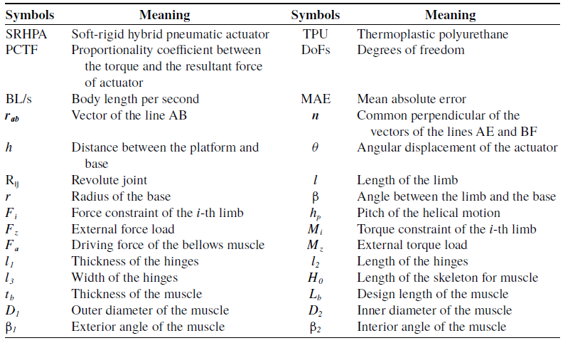
Appendix A: List of symbols and abbreviations
Table A.I. The list of symbols and abbreviations for the proposed actuator and inchworm robot.


 Open access