


1. Introduction
For the last decades, robotic automation has crucially affected industry, especially the manufacturing and assembly of products as well as logistics [Reference Dauth, Findeisen, Suedekum and Woessner1, Reference Graetz and Michaels2]. Physical work has often become superfluous due to the usage of robotic manipulators leading to a raised standard of living in leading industrialized nations. In addition to that, robotics inevitably has proliferated into the service sector and everyday tasks such as vacuum cleaning, lawn mowing, and as healthcare robots [Reference Gates3]. However, while the scale and intricacy of tasks a robot could accomplish has been increasing for years, continuously developing larger or more sophisticated individual robots appears not to be expedient for a large class of contemporary problems, for example, transporting a heavy or large-scale load in logistics or when searching for missing persons in vast areas. In this context, the cooperation of multiple simple robots appears promising for tasks which are beyond the range of what is possible for a single robot [Reference Rizk, Awad and Tunstel4]. The multi-robot approach has further been accelerated by the continuous progress in communication technology and processing units yielding lightweight and cost-efficient hardware, nurturing the hope that robotic swarms can solve highly complex as well as large-scale tasks due to their flexible configurability and the increased spatial distribution. Although utilizing a group of mobile robots is very auspicious to solve such tasks, it brings along some challenges that do not appear when using only an individual robot. In order to avoid a single link of failure, solving the task at hand without a central entity comes at the cost of fully decentralized algorithms which are significantly more complex than centralized ones. For efficient operation, inter-robot communication is inevitable including the agents’ self-reliant synchronization. Furthermore, in addition to decentralized (control) algorithms, explicit coordination and decision-making structures are indispensable.
A popular model problem in distributed robotics is the cooperative transport of an object. While this task has been tackled in many ways, for example, by grasping [Reference Groß and Dorigo5, Reference Wang and Schwager6] or caging [Reference Dai, Kim, Wee, Lee and Lee7, Reference Wan, Shi, Wang and Fukui8] the object, this paper investigates a pushing-only strategy in which the robots are not physically attached to the object but only push it at specific points. This approach has the advantage that the mobile robots do not need to be equipped with a grasping device, which may overcomplicate the robot and represents a possible link of failure. Numerous schemes have been proposed in recent years dealing with the topic of pushing-only strategies, see, for example, the overview given in [Reference Tuci, Alkilabi and Akanyeti9]. However, while most of them are explicitly designed for a fixed number of robots or a specific object shape, for example, for rectangular boxes [Reference Alkilabi, Narayan and Tuci10], the approach developed in [Reference Ebel11] introduces an optimization-based scheme that stands out regarding its versatility w. r. t. the number of employed mobile robots and the consideration of arbitrary objects of polygonal shape. Since the robots are only able to push the object, they reorganize themselves around the object in a self-reliant fashion depending on the current manipulation objective. Self-reliant reorganization is enabled by formulating and solving the manipulation problem as a geometrically intuitive optimization problem leading to unprecedented flexibility. The obtained formation is then governed by means of a distributed predictive controller such that any geometric formation can precisely be retained. Notably, this scheme, as well as most of the others proposed in the literature, relies only on the control of the robots’ positions. While the position-based approach stands to reason, also since (mobile) robots are naturally controlled on position-level, it reveals some limitations. For instance, in order to ensure that the group is able to transport the object, often a large number of agents is employed since it is not clear how many of them are necessary to exert large-enough forces. Otherwise, the scheme lacks robustness. Furthermore, relying on position information only, due to imperfect measurements and information on the object’s shape, the robots cannot determine with certainty whether they are already in contact with the object or not. Another intrinsic limitation of purely position-based schemes is that they do not have any information about the interaction between the robots and the object, possibly leading to large contact forces damaging the robots or the object. Further, from a control perspective, the object to be manipulated acts as a disturbance on the robots’ position controllers and not as the actual control goal.
These exemplary challenges can be tackled by investigating the problem on force level, that is, choosing formations based on dynamic considerations and, moreover, explicitly controlling the interaction forces between the agents and the object to be manipulated. Although this approach has been less prominent than position-based schemes some remarkable work has been done in recent years. In [Reference Wang and Schwager6, Reference Wang and Schwager12], multiple follower robots perceive and amplify the force exerted by a pulling leader robot in order to transport a rectangular box. In [Reference Neumann, Chin and Kitts13, Reference Neumann and Kitts14], a central instance computes off-board a desired force, which two robots shall exert on a rectangular object to push it along a line. However, these force-based approaches fall far short of the flexibility and performance of the fully decentralized position-based scheme proposed in [Reference Ebel11]. The goal of this paper is to close this gap.
To this end, this paper novelly introduces a distributed and very flexible scheme based on the consideration and control of the forces exerted by the mobile robots. The main contributions are twofold. First, to the best of our knowledge and based on our findings in [Reference Rosenfelder, Ebel and Eberhard15, Reference Rosenfelder, Ebel, Eberhard, Petrič, Ude and Žlajpah16], it is the first time that the benchmark problem has solely been tackled based on dynamic considerations, that is, by explicitly taking into account the robots’ pushing capabilities already at the stage of (re-)allocating the robots around the object. This novel approach is of particular interest since the force-based consideration is generic and reaches beyond the scope of the benchmark problem. Therefore, the proposed approach can serve as a blueprint for general cooperative force-based manipulation tasks, for example, also when working with drones or deformable objects. Second, based on the previous contribution, it is the first time that a broad class of objects has been transported along arbitrary paths by explicitly controlling the interacting forces on lightweight onboard hardware, which is in contrast to [Reference Rosenfelder, Ebel, Eberhard, Petrič, Ude and Žlajpah16], by utilizing a tailored quadratic program and a hybrid position-force controller. It might even be the first time that contact forces have explicitly been governed in such preciseness by mobile robots. Notably, the overall framework is implemented based on the software architecture presented in [Reference Ebel11] tailored for distributed robotics. Therein, real-time critical tasks and less time-critical organization tasks are partitioned into two separate, although communicating, programs per robot, see also [Reference Ebel and Eberhard17] for a comprehensive overview. Thus, the versatility and flexibility of the position-based approach is widely retained, as it is demonstrated by means of various hardware experiments.
The remainder of the paper is structured as follows. The problem setup including the employed omnidirectional mobile robots is described in Section 2. In Section 3, the force-based formation synthesis is discussed. The underlying optimization-based control concept including a hybrid position-force controller is proposed in Section 4 constituting the main contribution. The functionality and versatility of the overall scheme as well as the performance of the force controller are demonstrated in Section 5 in several hardware scenarios before Section 6 gives a summary and an outlook.
2. Problem setup
The object to be transported shall be any rigid body of polygonal, possibly non-convex, shape with even mass distribution. The overall goal is that
 $N\in \mathbb{Z}_{\geq 3}$
omnidirectional mobile robots cooperatively push the object such that it is moved along a predefined path through the plane, that is, a sequence of points describing the object’s desired position and orientation. It is assumed that the object and the robots are not subject to any kinematic constraint such that they can move and rotate freely on the floor. For the robots, this is put into practice by using tailor-made Mecanum-wheeled mobile robots with a circular footprint of radius
$N\in \mathbb{Z}_{\geq 3}$
omnidirectional mobile robots cooperatively push the object such that it is moved along a predefined path through the plane, that is, a sequence of points describing the object’s desired position and orientation. It is assumed that the object and the robots are not subject to any kinematic constraint such that they can move and rotate freely on the floor. For the robots, this is put into practice by using tailor-made Mecanum-wheeled mobile robots with a circular footprint of radius
 $r_{\text{r}}\in \mathbb{R}_{\gt 0}$
, see Fig. 1. Crucially, each mobile robot is equipped with one cost-efficient force-sensing unit consisting of a compact load cell and a leaf-spring construction, where the latter is decisive for preloading and to filter the acting contact force such that only normal forces are applied to the load cell. This enables the robot to measure the contact force along the unit’s longitudinal axis. Notation-wise, for robot
$r_{\text{r}}\in \mathbb{R}_{\gt 0}$
, see Fig. 1. Crucially, each mobile robot is equipped with one cost-efficient force-sensing unit consisting of a compact load cell and a leaf-spring construction, where the latter is decisive for preloading and to filter the acting contact force such that only normal forces are applied to the load cell. This enables the robot to measure the contact force along the unit’s longitudinal axis. Notation-wise, for robot
 $i\in \mathbb{Z}_{1:N}\,=\!:\,\mathcal{N}$
this force is denoted by
$i\in \mathbb{Z}_{1:N}\,=\!:\,\mathcal{N}$
this force is denoted by
 $f_i$
and its desired force acting on the object is constrained to
$f_i$
and its desired force acting on the object is constrained to
 $[0,\bar{f}_{i}]$
,
$[0,\bar{f}_{i}]$
,
 $\bar{f}_i\gt 0$
, due to the robot’s limited amount of power and the present slip, where non-negativity of the desired force follows from the non-prehensile contact. Further, the forces all robots exert on the object are cast into the vector
$\bar{f}_i\gt 0$
, due to the robot’s limited amount of power and the present slip, where non-negativity of the desired force follows from the non-prehensile contact. Further, the forces all robots exert on the object are cast into the vector
 $\boldsymbol{f}_{\text{r}} ={\begin{bmatrix} f_1 & \cdots & f_N \end{bmatrix}}^{\mathsf{T}}\in \mathcal{F}\,:\!=\, [0,\, \bar{f}_1]\times \dots \times [0,\, \bar{f}_N] \subset \mathbb{R}^N_{\geq 0}$
. The robots’ forces are exerted normal to the corresponding edge of the object, see Fig. 2(b), since its positioning with respect to the corresponding edge of the object is assumed to be stable, where the latter is realized by the underlying controller dealt with later in the paper.
$\boldsymbol{f}_{\text{r}} ={\begin{bmatrix} f_1 & \cdots & f_N \end{bmatrix}}^{\mathsf{T}}\in \mathcal{F}\,:\!=\, [0,\, \bar{f}_1]\times \dots \times [0,\, \bar{f}_N] \subset \mathbb{R}^N_{\geq 0}$
. The robots’ forces are exerted normal to the corresponding edge of the object, see Fig. 2(b), since its positioning with respect to the corresponding edge of the object is assumed to be stable, where the latter is realized by the underlying controller dealt with later in the paper.
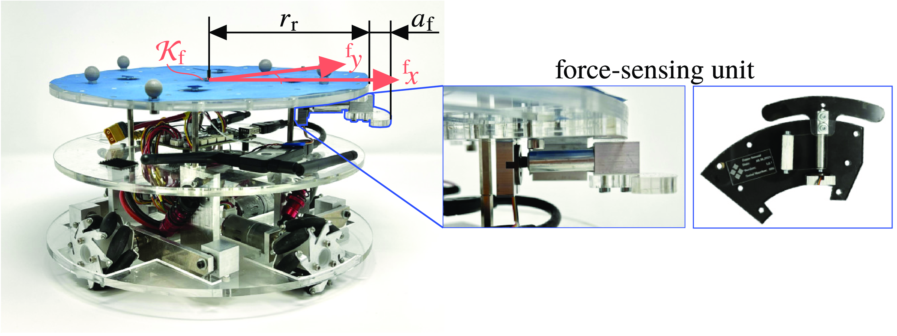
Figure 1. Photograph of the employed omnidirectional mobile robot equipped with a force-sensing unit.

Figure 2. Left: Illustration of an exemplary polygonal object (dark gray) and its dilated edges (dark blue). Middle: Potential placement of the mobile robots around the object. Right: Projection of the obtained zonotope at
 $\tau =\tau _{\text{des}}$
(blue) and rhombus (green) for constraint softening for the configuration depicted in the middle. (a) Dilated edges of the object. (b) Contact normals and lever arms. (c) Constraint softening for
$\tau =\tau _{\text{des}}$
(blue) and rhombus (green) for constraint softening for the configuration depicted in the middle. (a) Dilated edges of the object. (b) Contact normals and lever arms. (c) Constraint softening for
 $^{\text{S}}\boldsymbol{f}_{\text{des}}\notin \mathcal{G}(\boldsymbol{w})$
.
$^{\text{S}}\boldsymbol{f}_{\text{des}}\notin \mathcal{G}(\boldsymbol{w})$
.
To manipulate the object as desired, the robotic swarm shall cooperatively exert some desired generalized force
 $\boldsymbol{f}_{\text{d}}$
. The latter consists of a planar pushing force
$\boldsymbol{f}_{\text{d}}$
. The latter consists of a planar pushing force
 $\boldsymbol{f}_{\text{t,des}}\in \mathbb{R}^2$
and a torque
$\boldsymbol{f}_{\text{t,des}}\in \mathbb{R}^2$
and a torque
 $\tau _{\text{des}}$
w. r. t. the object’s center of mass, that is,
$\tau _{\text{des}}$
w. r. t. the object’s center of mass, that is,
 $\boldsymbol{f}^{\mathsf{T}}_{\text{d}}=\begin{bmatrix} \boldsymbol{f}_{\text{t,des}}^{\mathsf{T}} & \tau _{\text{des}}\end{bmatrix}\in \mathbb{R}^3$
. Usually, the desired force
$\boldsymbol{f}^{\mathsf{T}}_{\text{d}}=\begin{bmatrix} \boldsymbol{f}_{\text{t,des}}^{\mathsf{T}} & \tau _{\text{des}}\end{bmatrix}\in \mathbb{R}^3$
. Usually, the desired force
 $\boldsymbol{f}_{\text{d}}$
is determined based on the current posture of the object with respect to the predefined path. To this end, each mobile robot is assumed to have information about the object’s shape and current posture as well as the current postures of the other robots. It is therefore essential that the agents are able to communicate among each other via a wireless network. If the assumption that the robots know the object’s shape a priori does not hold, onboard distance sensors could be used to cooperatively gather data in order to reconstruct the actual polygonal object shape in a discovery phase executed before the transportation process begins. It is worth noting that the aforementioned assumptions are not very strict and hold for several real-world application scenarios, for example, hauling a variety of known transport receptacles in a warehouse or manufacturing facility equipped with a localization system.
$\boldsymbol{f}_{\text{d}}$
is determined based on the current posture of the object with respect to the predefined path. To this end, each mobile robot is assumed to have information about the object’s shape and current posture as well as the current postures of the other robots. It is therefore essential that the agents are able to communicate among each other via a wireless network. If the assumption that the robots know the object’s shape a priori does not hold, onboard distance sensors could be used to cooperatively gather data in order to reconstruct the actual polygonal object shape in a discovery phase executed before the transportation process begins. It is worth noting that the aforementioned assumptions are not very strict and hold for several real-world application scenarios, for example, hauling a variety of known transport receptacles in a warehouse or manufacturing facility equipped with a localization system.
In order to enable the robots to cooperatively exert the desired generalized force, it is crucial in a first step to place them around the object in a way that is expedient for the current manipulation objective. This is dealt with in the subsequent section, which mainly uses the findings from [Reference Rosenfelder, Ebel, Eberhard, Petrič, Ude and Žlajpah16]. Thus, the following force-based formation synthesis is not discussed in full detail. However, to keep this paper self-contained, and since the approach paves the way to control design, the main concept of the force-based formation finding is discussed. It is important to underline that the subsequent formation synthesis problem is not only an initial question but rather runs ad infinitum and detached from real-time control tasks (Section 4) allowing for continuous reorganization. Thus, the scheme can intrinsically deal with paths adapted online or is able to solve situations where the object is moved beyond its actual desired posture, for instance.
The following investigations are done in the object-fixed frame of reference
 $\mathcal{K}_{\text{s}}$
, located in the object’s center of mass. Where necessary, we add a superscript in front of variables to emphasize the frame of reference in which the variable is given, for example,
$\mathcal{K}_{\text{s}}$
, located in the object’s center of mass. Where necessary, we add a superscript in front of variables to emphasize the frame of reference in which the variable is given, for example,
 $^{\text{s}}\boldsymbol{v}$
for the variable
$^{\text{s}}\boldsymbol{v}$
for the variable
 $\boldsymbol{v}$
given in the coordinates of frame
$\boldsymbol{v}$
given in the coordinates of frame
 $\mathcal{K}_{\text{s}}$
.
$\mathcal{K}_{\text{s}}$
.
3. Force-based formation synthesis
Before deriving a concept on how to deploy the robots around the object, it is important to describe feasible contact points between a robot and the object’s edges in a mathematically sound manner. Therefore, the object’s edges are moved outwards by a distance
 $r_{\text{f}} = r_{\text{r}} + a_{\text{f}}$
, where
$r_{\text{f}} = r_{\text{r}} + a_{\text{f}}$
, where
 $a_{\text{f}} \in \mathbb{R}_{\gt 0}$
is the protrusion of the force-sensing unit, see Fig. 1. The obtained dilated edges are then clipped by some safety margins at pointed and concave corners in order to ensure that the robot’s pushing direction is uniquely defined and that there is only one contact point per robot, see Fig. 2(a). The latter requirement is necessary since each robot is only able to measure the force along one axis, corresponding to the longitudinal direction of the force-sensing unit, that is, along the
$a_{\text{f}} \in \mathbb{R}_{\gt 0}$
is the protrusion of the force-sensing unit, see Fig. 1. The obtained dilated edges are then clipped by some safety margins at pointed and concave corners in order to ensure that the robot’s pushing direction is uniquely defined and that there is only one contact point per robot, see Fig. 2(a). The latter requirement is necessary since each robot is only able to measure the force along one axis, corresponding to the longitudinal direction of the force-sensing unit, that is, along the
 $^{\text{f}}x$
-axis of the robot-fixed frame of reference
$^{\text{f}}x$
-axis of the robot-fixed frame of reference
 $\mathcal{K}_{\text{f}}$
, see Fig. 1. Finally, one obtains a closed set
$\mathcal{K}_{\text{f}}$
, see Fig. 1. Finally, one obtains a closed set
 $\mathcal{I}_{\text{e}}\subset \mathbb{R}_{\geq 0}$
of one-dimensional positions along the dilated edges corresponding to feasible positions of the robot’s center, which is the origin of
$\mathcal{I}_{\text{e}}\subset \mathbb{R}_{\geq 0}$
of one-dimensional positions along the dilated edges corresponding to feasible positions of the robot’s center, which is the origin of
 $\mathcal{K}_{\text{f}}$
, see Fig. 2(a) for the example of a
$\mathcal{K}_{\text{f}}$
, see Fig. 2(a) for the example of a
 $+$
-shaped object.
$+$
-shaped object.
The formation synthesis problem can now be understood as finding for all robots an overall configuration
 $\boldsymbol{w}\,:\!=\,{\begin{bmatrix} w_1 & \cdots & w_N \end{bmatrix}}^{\mathsf{T}}$
,
$\boldsymbol{w}\,:\!=\,{\begin{bmatrix} w_1 & \cdots & w_N \end{bmatrix}}^{\mathsf{T}}$
,
 $w_i\in \mathcal{I}_{\text{e}}$
,
$w_i\in \mathcal{I}_{\text{e}}$
,
 $i\in \mathcal{N}$
, which is able to cooperatively exert the force
$i\in \mathcal{N}$
, which is able to cooperatively exert the force
 $^{\text{s}}\boldsymbol{f}_{\text{d}}$
on the object. For each position
$^{\text{s}}\boldsymbol{f}_{\text{d}}$
on the object. For each position
 $w_i\in \mathcal{I}_{\text{e}}$
, the corresponding edge’s inner normal vector
$w_i\in \mathcal{I}_{\text{e}}$
, the corresponding edge’s inner normal vector
 $\boldsymbol{n}_i \,:\!=\, \, ^{\text{s}}\boldsymbol{n}(w_i)\in \mathbb{R}^2$
,
$\boldsymbol{n}_i \,:\!=\, \, ^{\text{s}}\boldsymbol{n}(w_i)\in \mathbb{R}^2$
,
 $\| \boldsymbol{n}_i \|_2 = 1$
, as well as its lever arm
$\| \boldsymbol{n}_i \|_2 = 1$
, as well as its lever arm
 $\ell _i\,:\!=\, \ell (w_i)$
w. r. t. the object’s center of mass can be determined, which correspond to the individual pushing direction and rotation capability of the chosen position
$\ell _i\,:\!=\, \ell (w_i)$
w. r. t. the object’s center of mass can be determined, which correspond to the individual pushing direction and rotation capability of the chosen position
 $w_i$
, respectively, see Fig. 2(b).
$w_i$
, respectively, see Fig. 2(b).
Extending the previous description of each agent’s individual manipulation capability to the configuration
 $\boldsymbol{w}$
, the so-called grasp map [Reference Prattichizzo, Trinkle, Siciliano and Khatib18]
$\boldsymbol{w}$
, the so-called grasp map [Reference Prattichizzo, Trinkle, Siciliano and Khatib18]
 \begin{equation} \boldsymbol{G}(\boldsymbol{w}) = \begin{bmatrix} ^{\text{s}}\boldsymbol{n}(w_1) & \cdots & ^{\text{s}}\boldsymbol{n}(w_N) \\[4pt] \ell (w_1) & \cdots & \ell (w_N) \\[4pt] \end{bmatrix}\in \mathbb{R}^{3\times N} \end{equation}
is obtained which describes the overall manipulation characteristics of the chosen configuration in the object-fixed frame of reference. The generalized force the object is manipulated with then follows as
 \begin{equation} ^{\text{s}}\boldsymbol{f}_{\text{e}}= \boldsymbol{G}(\boldsymbol{w})\, \boldsymbol{f}_{\text{r}}, \quad \boldsymbol{f}_{\text{r}}\in \mathcal{F}. \end{equation}
Since the maximum pushing force
 $\bar{f}_{i}$
is finite for all
$\bar{f}_{i}$
is finite for all
 $i\in \mathcal{N}$
,
$i\in \mathcal{N}$
,
 $\mathcal{F}$
is an
$\mathcal{F}$
is an
 $N$
-dimensional hypercube, where edge
$N$
-dimensional hypercube, where edge
 $i$
is of length
$i$
is of length
 $\bar{f}_i$
, such that we obtain a closed set
$\bar{f}_i$
, such that we obtain a closed set
 $\mathcal{G}$
(
$\mathcal{G}$
(
 $\boldsymbol{w}$
) as the manipulation space, that is, the set which contains all generalized forces
$\boldsymbol{w}$
) as the manipulation space, that is, the set which contains all generalized forces
 $^{\text{s}}\boldsymbol{f}_{\text{e}}$
that can be exerted by the current configuration. The linear mapping (2) and the obtained set
$^{\text{s}}\boldsymbol{f}_{\text{e}}$
that can be exerted by the current configuration. The linear mapping (2) and the obtained set
 $\mathcal{G}$
(
$\mathcal{G}$
(
 $\boldsymbol{w}$
) are geometrically interpretable. In particular, since the individual manipulation capability of robot
$\boldsymbol{w}$
) are geometrically interpretable. In particular, since the individual manipulation capability of robot
 $i$
can be described by the line segment
$i$
can be described by the line segment
 $\bar{f}_i \,\boldsymbol{g}(w_i)$
in the three-dimensional manipulation space,
$\bar{f}_i \,\boldsymbol{g}(w_i)$
in the three-dimensional manipulation space,
 $\mathcal{G}$
(
$\mathcal{G}$
(
 $\boldsymbol{w}$
) follows as the Minkowski sum of all robots’ line segments and, therefore, is a zonotope [Reference Ziegler19]. Note that
$\boldsymbol{w}$
) follows as the Minkowski sum of all robots’ line segments and, therefore, is a zonotope [Reference Ziegler19]. Note that
 $\boldsymbol{g}(w_i)$
corresponds to the
$\boldsymbol{g}(w_i)$
corresponds to the
 $i$
th column of the grasp map (1). An example of the resulting three-dimensional zonotope, that is, a zonohedron, can be found in [Reference Rosenfelder, Ebel, Eberhard, Petrič, Ude and Žlajpah16, Fig. 2(a)]. In addition, one of the videos provided in [Reference Rosenfelder, Ebel and Eberhard20] contains an exemplary visualization of the generators
$i$
th column of the grasp map (1). An example of the resulting three-dimensional zonotope, that is, a zonohedron, can be found in [Reference Rosenfelder, Ebel, Eberhard, Petrič, Ude and Žlajpah16, Fig. 2(a)]. In addition, one of the videos provided in [Reference Rosenfelder, Ebel and Eberhard20] contains an exemplary visualization of the generators
 $\bar{f}_i \,\boldsymbol{g}(w_i)$
and the resulting zonohedra corresponding to a hardware experiment appearing later in this paper, see Fig. 4(a).
$\bar{f}_i \,\boldsymbol{g}(w_i)$
and the resulting zonohedra corresponding to a hardware experiment appearing later in this paper, see Fig. 4(a).
Alternatively, the resulting zonotope can also be interpreted as the projection of the hypercube
 $\mathcal{F}$
to the three-dimensional manipulation space, where the grasp map (1) acts as the projection matrix. For more details on the geometric interpretation and characteristics of the resulting zonotope we refer the interested reader to [Reference Rosenfelder, Ebel, Eberhard, Petrič, Ude and Žlajpah16, Sec. 3]. However, this descriptive geometric point of view allows to directly formulate necessary and desirable conditions on different configurations
$\mathcal{F}$
to the three-dimensional manipulation space, where the grasp map (1) acts as the projection matrix. For more details on the geometric interpretation and characteristics of the resulting zonotope we refer the interested reader to [Reference Rosenfelder, Ebel, Eberhard, Petrič, Ude and Žlajpah16, Sec. 3]. However, this descriptive geometric point of view allows to directly formulate necessary and desirable conditions on different configurations
 $\boldsymbol{w}$
. As the main requirement, a configuration
$\boldsymbol{w}$
. As the main requirement, a configuration
 $\boldsymbol{w}$
is feasible for the current manipulation objective
$\boldsymbol{w}$
is feasible for the current manipulation objective
 $^{\text{s}}\boldsymbol{f}_{\text{d}}$
if the latter is contained in the spanned zonotope, that is,
$^{\text{s}}\boldsymbol{f}_{\text{d}}$
if the latter is contained in the spanned zonotope, that is,
 $^{\text{s}}\boldsymbol{f}_{\text{d}}\in \mathcal{G}(\boldsymbol{w})$
. Further, it is desirable that
$^{\text{s}}\boldsymbol{f}_{\text{d}}\in \mathcal{G}(\boldsymbol{w})$
. Further, it is desirable that
 $^{\text{s}}\boldsymbol{f}_{\text{d}}$
is not close to any facet of
$^{\text{s}}\boldsymbol{f}_{\text{d}}$
is not close to any facet of
 $\mathcal{G}$
(
$\mathcal{G}$
(
 $\boldsymbol{w}$
), see also Fig. 2(c), introducing robustness such that the chosen configuration
$\boldsymbol{w}$
), see also Fig. 2(c), introducing robustness such that the chosen configuration
 $\boldsymbol{w}$
can also exert generalized forces close to the current one. Note that such changes in
$\boldsymbol{w}$
can also exert generalized forces close to the current one. Note that such changes in
 $^{\text{s}}\boldsymbol{f}_{\text{d}}$
often occur in the course of time for continuously differentiable paths. Here, two geometric properties are chosen as robustness measurements. In order to be able to tackle rotations which are close to the currently desired one (
$^{\text{s}}\boldsymbol{f}_{\text{d}}$
often occur in the course of time for continuously differentiable paths. Here, two geometric properties are chosen as robustness measurements. In order to be able to tackle rotations which are close to the currently desired one (
 $\tau _{\text{des}}$
), the minimal distance from
$\tau _{\text{des}}$
), the minimal distance from
 $^{\text{s}}\boldsymbol{f}_{\text{d}}$
to one of the facets in the manipulation space’s
$^{\text{s}}\boldsymbol{f}_{\text{d}}$
to one of the facets in the manipulation space’s
 $\tau$
-direction, which is perpendicular to the planar projection of
$\tau$
-direction, which is perpendicular to the planar projection of
 $\mathcal{G}$
(
$\mathcal{G}$
(
 $\boldsymbol{w}$
) at
$\boldsymbol{w}$
) at
 $\tau =\tau _{\text{des}}$
given in Fig. 2(c), constitutes a metric
$\tau =\tau _{\text{des}}$
given in Fig. 2(c), constitutes a metric
 $J_{\text{r}}$
. Analogously, the cost term
$J_{\text{r}}$
. Analogously, the cost term
 $J_{\text{t}}$
is chosen as a metric such that configurations are preferred which are robust w. r. t. the direction of the desired translational force
$J_{\text{t}}$
is chosen as a metric such that configurations are preferred which are robust w. r. t. the direction of the desired translational force
 $^{\text{s}}\boldsymbol{f}_{\text{t,des}}$
. For more details, the interested reader is referred to [Reference Rosenfelder, Ebel, Eberhard, Petrič, Ude and Žlajpah16, Sec. 3, Fig. 2(b)].
$^{\text{s}}\boldsymbol{f}_{\text{t,des}}$
. For more details, the interested reader is referred to [Reference Rosenfelder, Ebel, Eberhard, Petrič, Ude and Žlajpah16, Sec. 3, Fig. 2(b)].
Finally, the formation synthesis problem is formulated by means of an optimization problem. In particular, in order to solve the task at hand, necessary conditions to push and rotate the object in the currently desired direction are cast into constraints, whereas desirable properties are considered by means of an objective function yielding
 \begin{align} \underset{\boldsymbol{w}\in \mathbb{R}^N_{\geq 0}}{\text{minimize}} &\quad - c_1 J_{\text{t}}(\boldsymbol{w}) - c_2 J_{\text{r}}(\boldsymbol{w}) \end{align}
 \begin{align} \text{subject to} &\quad \exists\, \tilde{\boldsymbol{f}}_{\text{r}}\in \mathcal{F} \ \text{satisfying } \boldsymbol{G}(\boldsymbol{w})\, \tilde{\boldsymbol{f}}_{\text{r}} = \, ^{\text{s}}\boldsymbol{f}_{\text{d},} \end{align}
 \begin{align}&\quad \text{frD} \left ( w_i, \,w_j \right ) \geq d_{\text{min}} \quad \forall i\neq j, \end{align}
where
 $c_1,\,c_2\in \mathbb{R}_{\gt 0}$
and
$c_1,\,c_2\in \mathbb{R}_{\gt 0}$
and
 $d_{\text{min}}\in \mathbb{R}_{\gt 2 r_{\text{f}}}$
. Therein, the second constraint (3c) considers the free Euclidean distance (frD) between two positions ensuring that the robots are not placed too close to each other to avoid collisions.
$d_{\text{min}}\in \mathbb{R}_{\gt 2 r_{\text{f}}}$
. Therein, the second constraint (3c) considers the free Euclidean distance (frD) between two positions ensuring that the robots are not placed too close to each other to avoid collisions.
In order to solve the task at hand, it is crucial that a formation fulfills the constraints (3b) and (3c). In addition to that, the cost function (3a) quantifies how good the respective configuration is in terms of the proposed cost terms
 $J_{\text{t}}$
and
$J_{\text{t}}$
and
 $J_{\text{r}}$
, which are actually a design choice, see also [Reference Rosenfelder, Ebel, Eberhard, Petrič, Ude and Žlajpah16]. Attaining the minimum of the formation synthesis problem (3) results in an optimal behavior with respect to the designed cost, that is, usually increasing the formation’s robustness w.r.t. other pushing directions and thus, expecting to require less frequent reorganizations. However, it is important to stress that all crucial, necessary aspects for successful transportation are encoded in the constraints, whereas the cost therefore has and can have a more heuristic character.
$J_{\text{r}}$
, which are actually a design choice, see also [Reference Rosenfelder, Ebel, Eberhard, Petrič, Ude and Žlajpah16]. Attaining the minimum of the formation synthesis problem (3) results in an optimal behavior with respect to the designed cost, that is, usually increasing the formation’s robustness w.r.t. other pushing directions and thus, expecting to require less frequent reorganizations. However, it is important to stress that all crucial, necessary aspects for successful transportation are encoded in the constraints, whereas the cost therefore has and can have a more heuristic character.
Notably, the obtained optimization problem is non-convex and discontinuous in the optimization variable
 $\boldsymbol{w}$
such that a (distributed) augmented Lagrangian particle swarm optimization algorithm is employed [Reference Ebel11, Reference Ebel and Eberhard21, Reference Sedlaczek and Eberhard22]. Once a feasible solution is found, or one that is preferable to the current one, the robots negotiate in a self-reliant manner which position to take and drive to their respective attack point using the negotiation scheme proposed in [Reference Ebel and Eberhard23] and the grid-based navigation described in [Reference Ebel11, Sec. 5.3].
$\boldsymbol{w}$
such that a (distributed) augmented Lagrangian particle swarm optimization algorithm is employed [Reference Ebel11, Reference Ebel and Eberhard21, Reference Sedlaczek and Eberhard22]. Once a feasible solution is found, or one that is preferable to the current one, the robots negotiate in a self-reliant manner which position to take and drive to their respective attack point using the negotiation scheme proposed in [Reference Ebel and Eberhard23] and the grid-based navigation described in [Reference Ebel11, Sec. 5.3].
It is worth highlighting that the employed optimization problem (3) is based on a quasi-static consideration (3b) which is justifiable since neither the robots nor the object are subject to kinematic constraints and, moreover, transportation velocities are low in general. However, finding formations for more dynamic settings can be accomplished by taking into account the robots’ and object’s equations of motion within optimization problem (3). Further, this becomes especially crucial if the robots or the object are subject to kinematic constraints. For instance, in our prior work [Reference Ebel, Fahse, Rosenfelder and Eberhard24], in a setting with robots with non-holonomic kinematic constraints, the equations of motion of robots and object have been incorporated into the formation synthesis problem. That approach could straightforwardly be carried over to (3). The subsequent section deals with this paper’s focal point of how the forces to be exerted are determined and governed using decentralized hybrid position-force controllers based on the introduced geometric interpretation of the spanned manipulation space.
4. Control design
The overall control design is divided into two steps. In the first phase, a local model predictive controller (MPC) on position level is used to drive the robot in question to its desired pose along the dilated edge. Once the robot has reached a certain neighborhood of its goal pose, the MPC controller is switched off and the robot cautiously approaches the object until it is in contact with the object which is detected by the onboard force-sensing unit. This explicit contact detection highlights an important advantage compared to the purely position-based approach. The cautious approach ensures that the impact force is not too large. However, if the contact characteristics are approximately known, modeling the impact as proposed in [Reference Roveda, Riva, Bucca and Piga25] could allow to determine a safe approach velocity in order to speed up this stage.
During all stages, each robot communicates its status in the network. Once all robots are in contact with the object in a certain neighborhood of their desired posture along the dilated edge, a decentralized hybrid position-force controller is employed to govern the individual exerted force and to keep its relative pose to the object. Before investigating this hybrid controller in more detail, naturally the question arises which individual forces should be governed since (3b) ensures only the existence of one solution at some asynchronous time instant.
4.1. Desired exerted forces
To determine the forces to be exerted, a control sub-program running at a fixed sampling rate solves another optimization problem in order to obtain the desired individual pushing force for the currently desired overall force
 $^{\text{s}} \boldsymbol{f}_{\text{d}}$
. The latter is subject to change due to new solutions of problem (3), which is solved asynchronously and at a slower timescale than the control problem discussed subsequently. Moreover, it may be overly restrictive to demand that exactly
$^{\text{s}} \boldsymbol{f}_{\text{d}}$
. The latter is subject to change due to new solutions of problem (3), which is solved asynchronously and at a slower timescale than the control problem discussed subsequently. Moreover, it may be overly restrictive to demand that exactly
 $^{\text{s}} \boldsymbol{f}_{\text{d}}$
is exerted, for example, if
$^{\text{s}} \boldsymbol{f}_{\text{d}}$
is exerted, for example, if
 $^{\text{s}} \boldsymbol{f}_{\text{d}}$
is not in but close to
$^{\text{s}} \boldsymbol{f}_{\text{d}}$
is not in but close to
 $\mathcal{G}$
(
$\mathcal{G}$
(
 $\boldsymbol{w}$
). For these situations, it is reasonable to soften condition (3b) such that it is no longer required to hold precisely by equality. It is then rather the goal that an overall force
$\boldsymbol{w}$
). For these situations, it is reasonable to soften condition (3b) such that it is no longer required to hold precisely by equality. It is then rather the goal that an overall force
 $^{\text{s}}\tilde{\boldsymbol{f}}\in \mathcal{G}(\boldsymbol{w})$
can be exerted which is in a specific neighborhood of
$^{\text{s}}\tilde{\boldsymbol{f}}\in \mathcal{G}(\boldsymbol{w})$
can be exerted which is in a specific neighborhood of
 $^{\text{s}} \boldsymbol{f}_{\text{d}}$
in order to increase the number of situations for which the given configuration meets the manipulation objective in essence. In particular, for the translational force, this neighborhood is chosen to be a rhombus with center
$^{\text{s}} \boldsymbol{f}_{\text{d}}$
in order to increase the number of situations for which the given configuration meets the manipulation objective in essence. In particular, for the translational force, this neighborhood is chosen to be a rhombus with center
 $\boldsymbol{f}_{\text{t,des}}$
, see the green region in Fig. 2(c), where one diagonal coincides with the direction of
$\boldsymbol{f}_{\text{t,des}}$
, see the green region in Fig. 2(c), where one diagonal coincides with the direction of
 $\boldsymbol{f}_{\text{t,des}}$
. Thus, the rhombus diagonals’ lengths are two independent degrees of freedom of how condition (3b) can be softened, where usually the length of the diagonal perpendicular to
$\boldsymbol{f}_{\text{t,des}}$
. Thus, the rhombus diagonals’ lengths are two independent degrees of freedom of how condition (3b) can be softened, where usually the length of the diagonal perpendicular to
 $\boldsymbol{f}_{\text{t,des}}$
is chosen smaller than the length of the parallel diagonal since the exerted force’s direction is more crucial than its absolute value due to friction and slippage. To analogously soften the requirement on the overall exerted torque, we allow for values in the interval
$\boldsymbol{f}_{\text{t,des}}$
is chosen smaller than the length of the parallel diagonal since the exerted force’s direction is more crucial than its absolute value due to friction and slippage. To analogously soften the requirement on the overall exerted torque, we allow for values in the interval
 $[\tau _{\text{des}}-\Delta \tau, \, \tau _{\text{des}}+\Delta \tau ]$
,
$[\tau _{\text{des}}-\Delta \tau, \, \tau _{\text{des}}+\Delta \tau ]$
,
 $\Delta \tau \in \mathbb{R}_{\gt 0}$
, which extrudes the aforementioned rhombus in the third dimension. Notably, if the rhombus’ diagonals and
$\Delta \tau \in \mathbb{R}_{\gt 0}$
, which extrudes the aforementioned rhombus in the third dimension. Notably, if the rhombus’ diagonals and
 $\Delta \tau$
are chosen as zero, one recovers the original stricter condition (3b). However, this constraint softening does not overcomplicate the original condition (3b) since the requirement that the obtained overall force is contained in the extruded rhombus can be written as a polytopic constraint
$\Delta \tau$
are chosen as zero, one recovers the original stricter condition (3b). However, this constraint softening does not overcomplicate the original condition (3b) since the requirement that the obtained overall force is contained in the extruded rhombus can be written as a polytopic constraint
 $\boldsymbol{C}_{\diamond } \, \boldsymbol{G}(\boldsymbol{w})\boldsymbol{f}_{\text{r}} \leq \boldsymbol{d}_{\diamond }$
, where
$\boldsymbol{C}_{\diamond } \, \boldsymbol{G}(\boldsymbol{w})\boldsymbol{f}_{\text{r}} \leq \boldsymbol{d}_{\diamond }$
, where
 $\boldsymbol{C}_{\diamond }\in \mathbb{R}^{6\times 3}$
and
$\boldsymbol{C}_{\diamond }\in \mathbb{R}^{6\times 3}$
and
 $\boldsymbol{d}_{\diamond } \in \mathbb{R}^6$
solely depend on the desired force
$\boldsymbol{d}_{\diamond } \in \mathbb{R}^6$
solely depend on the desired force
 $\boldsymbol{f}_{\text{d}}$
and the chosen softening parameters.
$\boldsymbol{f}_{\text{d}}$
and the chosen softening parameters.
In addition to this necessary condition, one can again formulate some desired properties regarding the forces
 $\boldsymbol{f}_{\text{r}}$
to be governed by the robots. First, although the original constraint has been softened by the introduced rhombus, it is still desirable to exert the generalized force
$\boldsymbol{f}_{\text{r}}$
to be governed by the robots. First, although the original constraint has been softened by the introduced rhombus, it is still desirable to exert the generalized force
 $^{\text{s}}\boldsymbol{f}_{\text{d}}$
as precisely as possible. Further, from a practical point of view, it might be beneficial if the forces exerted by the robots are close to a specific setpoint
$^{\text{s}}\boldsymbol{f}_{\text{d}}$
as precisely as possible. Further, from a practical point of view, it might be beneficial if the forces exerted by the robots are close to a specific setpoint
 $\boldsymbol{f}_{\text{set}}\in \mathcal{F}$
. As a third desirable condition, we seek to minimize the exerted forces of robots which counteract the desired motion of the object. To this end, the individual manipulation capabilities
$\boldsymbol{f}_{\text{set}}\in \mathcal{F}$
. As a third desirable condition, we seek to minimize the exerted forces of robots which counteract the desired motion of the object. To this end, the individual manipulation capabilities
 $\boldsymbol{g} (w_i)$
,
$\boldsymbol{g} (w_i)$
,
 $i\in \mathcal{N}$
, are projected on the desired overall force using the scalar product, yielding
$i\in \mathcal{N}$
, are projected on the desired overall force using the scalar product, yielding
 $\boldsymbol{G}^{\mathsf{T}} \, ^{\text{s}}\boldsymbol{f}_{\text{d}}$
for the overall formation.
$\boldsymbol{G}^{\mathsf{T}} \, ^{\text{s}}\boldsymbol{f}_{\text{d}}$
for the overall formation.
As before, the aforementioned desired conditions are put into a cost function of an optimization problem whereas the necessary condition of cooperatively exerting the generalized force
 $^{\text{s}}\boldsymbol{f}_{\text{d}}$
in essence forms a constraint.
$^{\text{s}}\boldsymbol{f}_{\text{d}}$
in essence forms a constraint.
In particular, the quadratic problem (QP) utilized to determine the individual pushing forces of the robots then reads
where
 $\boldsymbol{Q}\in \mathbb{R}^{3\times 3}$
,
$\boldsymbol{Q}\in \mathbb{R}^{3\times 3}$
,
 $\boldsymbol{R}\in \mathbb{R}^{N\times N}$
are some positive definite weighting matrices as well as
$\boldsymbol{R}\in \mathbb{R}^{N\times N}$
are some positive definite weighting matrices as well as
 $\tilde{q}\in \mathbb{R}_{\geq 0}$
, and we write
$\tilde{q}\in \mathbb{R}_{\geq 0}$
, and we write
 $\boldsymbol{G}$
instead of
$\boldsymbol{G}$
instead of
 $\boldsymbol{G}(\boldsymbol{w})$
for brevity. As for the formation finding problem (3), fulfilling the constraint (4b) is crucial in order to exert the overall force on the object. On top of that, attaining the objective function’s minimum may yield a particularly desirable solution, for example, in terms of robustness, see also the previous paragraph. Note that for
$\boldsymbol{G}(\boldsymbol{w})$
for brevity. As for the formation finding problem (3), fulfilling the constraint (4b) is crucial in order to exert the overall force on the object. On top of that, attaining the objective function’s minimum may yield a particularly desirable solution, for example, in terms of robustness, see also the previous paragraph. Note that for
 $\boldsymbol{R}=\textbf{0}$
and
$\boldsymbol{R}=\textbf{0}$
and
 $N\gt 3$
robots, the quadratic problem would not be strictly convex due to the positive semi-definite Hessian matrix
$N\gt 3$
robots, the quadratic problem would not be strictly convex due to the positive semi-definite Hessian matrix
 $\boldsymbol{G}^{\mathsf{T}} \boldsymbol{Q} \boldsymbol{G}$
. However, since we assume
$\boldsymbol{G}^{\mathsf{T}} \boldsymbol{Q} \boldsymbol{G}$
. However, since we assume
 $\boldsymbol{R}\succ 0$
and since the last term is linear in the optimization variable, the QP (4) attains a unique solution. Moreover, for a given configuration
$\boldsymbol{R}\succ 0$
and since the last term is linear in the optimization variable, the QP (4) attains a unique solution. Moreover, for a given configuration
 $\boldsymbol{w}$
(such that
$\boldsymbol{w}$
(such that
 $\boldsymbol{G}$
is constant), (4) parametrically depends on the desired manipulation
$\boldsymbol{G}$
is constant), (4) parametrically depends on the desired manipulation
 $^{\text{s}}\boldsymbol{f}_{\text{d}}$
which can be utilized by solvers such as [Reference Ferreau, Kirches, Potschka, Bock and Diehl26] to warm-start the program based on the previous solution. This is crucial to efficiently solve (4), also on lightweight onboard hardware, such that each robot obtains in a decentralized fashion a desired force value
$^{\text{s}}\boldsymbol{f}_{\text{d}}$
which can be utilized by solvers such as [Reference Ferreau, Kirches, Potschka, Bock and Diehl26] to warm-start the program based on the previous solution. This is crucial to efficiently solve (4), also on lightweight onboard hardware, such that each robot obtains in a decentralized fashion a desired force value
 $f_{i,{\text{des}}}$
which it should exert on the object using the hybrid controller, which is discussed subsequently.
$f_{i,{\text{des}}}$
which it should exert on the object using the hybrid controller, which is discussed subsequently.
4.2. Decentralized hybrid position-force controller
The two control goals of attacking the object’s edge at the desired point and exerting the desired force are subsequently investigated following an approach from robotic manipulators [Reference Raibert and Craig27] that considers the constraints imposed by the task.
Following [Reference Raibert and Craig27], the contact frame
 $\mathcal{K}_{\text{c}}$
is chosen to be placed at the desired contact point with its
$\mathcal{K}_{\text{c}}$
is chosen to be placed at the desired contact point with its
 $^{\text{c}}x$
-axis pointing along the edge’s inner normal vector, see Fig. 3, where w. l. o. g. the contact point of the
$^{\text{c}}x$
-axis pointing along the edge’s inner normal vector, see Fig. 3, where w. l. o. g. the contact point of the
 $i$
th robot is investigated in the following. As shown in Fig. 3, an additional piece of foam is mounted on the tip of the force-sensing unit’s runner for compliance purposes in order to avoid a chattering contact. As another consequence, the actual contact is only approximately a point contact. However, due to the leaf spring-based mounting of the force sensor (Fig. 1) and due to the robot’s very precise control of its orientation (see Section 5) with the sole purpose of orthogonally facing the object, the resulting interaction force, which is physically equivalent to the actual area load, is indeed primarily exerted and measured at the center of and normal to the runner, justifying the assumed point contact. Notably, the robot-fixed frame
$i$
th robot is investigated in the following. As shown in Fig. 3, an additional piece of foam is mounted on the tip of the force-sensing unit’s runner for compliance purposes in order to avoid a chattering contact. As another consequence, the actual contact is only approximately a point contact. However, due to the leaf spring-based mounting of the force sensor (Fig. 1) and due to the robot’s very precise control of its orientation (see Section 5) with the sole purpose of orthogonally facing the object, the resulting interaction force, which is physically equivalent to the actual area load, is indeed primarily exerted and measured at the center of and normal to the runner, justifying the assumed point contact. Notably, the robot-fixed frame
 $\mathcal{K}_{\text{f}}$
and the contact frame
$\mathcal{K}_{\text{f}}$
and the contact frame
 $\mathcal{K}_{\text{c}}$
thus have the same orientation in general. Then, for the given placement of the robot along the object’s edge, arising natural constraints are that it cannot intrude the object and that, for the assumed frictionless point contact, neither a tangential force nor a torque w. r. t. its contact point can be exerted by the robot on the object. Hence, the natural constraints read
$\mathcal{K}_{\text{c}}$
thus have the same orientation in general. Then, for the given placement of the robot along the object’s edge, arising natural constraints are that it cannot intrude the object and that, for the assumed frictionless point contact, neither a tangential force nor a torque w. r. t. its contact point can be exerted by the robot on the object. Hence, the natural constraints read
 $v_{^{\text{c}}x}=0$
as well as
$v_{^{\text{c}}x}=0$
as well as
 $f_{^{\text{c}}y}=0$
and
$f_{^{\text{c}}y}=0$
and
 $\tau _{^{\text{c}}z}=0$
, respectively. These natural constraints directly specify the force-controlled and position-controlled directions, respectively. The control goals of the orthogonal directions are then specified by means of artificial constraints including the desired force in the longitudinal direction and the robot’s pose at the contact point, that is,
$\tau _{^{\text{c}}z}=0$
, respectively. These natural constraints directly specify the force-controlled and position-controlled directions, respectively. The control goals of the orthogonal directions are then specified by means of artificial constraints including the desired force in the longitudinal direction and the robot’s pose at the contact point, that is,
 $f_{^{\text{c}}x}=f_{i,\text{des}}$
as well as
$f_{^{\text{c}}x}=f_{i,\text{des}}$
as well as
 $^{\text{c}} y=0$
and
$^{\text{c}} y=0$
and
 $^{\text{c}} \theta =0$
, respectively. For the given planar manipulation task, due to the omnidirectional character of the employed robots, this formulation and interpretation of the contact frame is rather intuitive since the overall task can be broken down into the two elementary control goals of concurrently exerting the desired force while keeping its relative pose w.r.t. the object.
$^{\text{c}} \theta =0$
, respectively. For the given planar manipulation task, due to the omnidirectional character of the employed robots, this formulation and interpretation of the contact frame is rather intuitive since the overall task can be broken down into the two elementary control goals of concurrently exerting the desired force while keeping its relative pose w.r.t. the object.
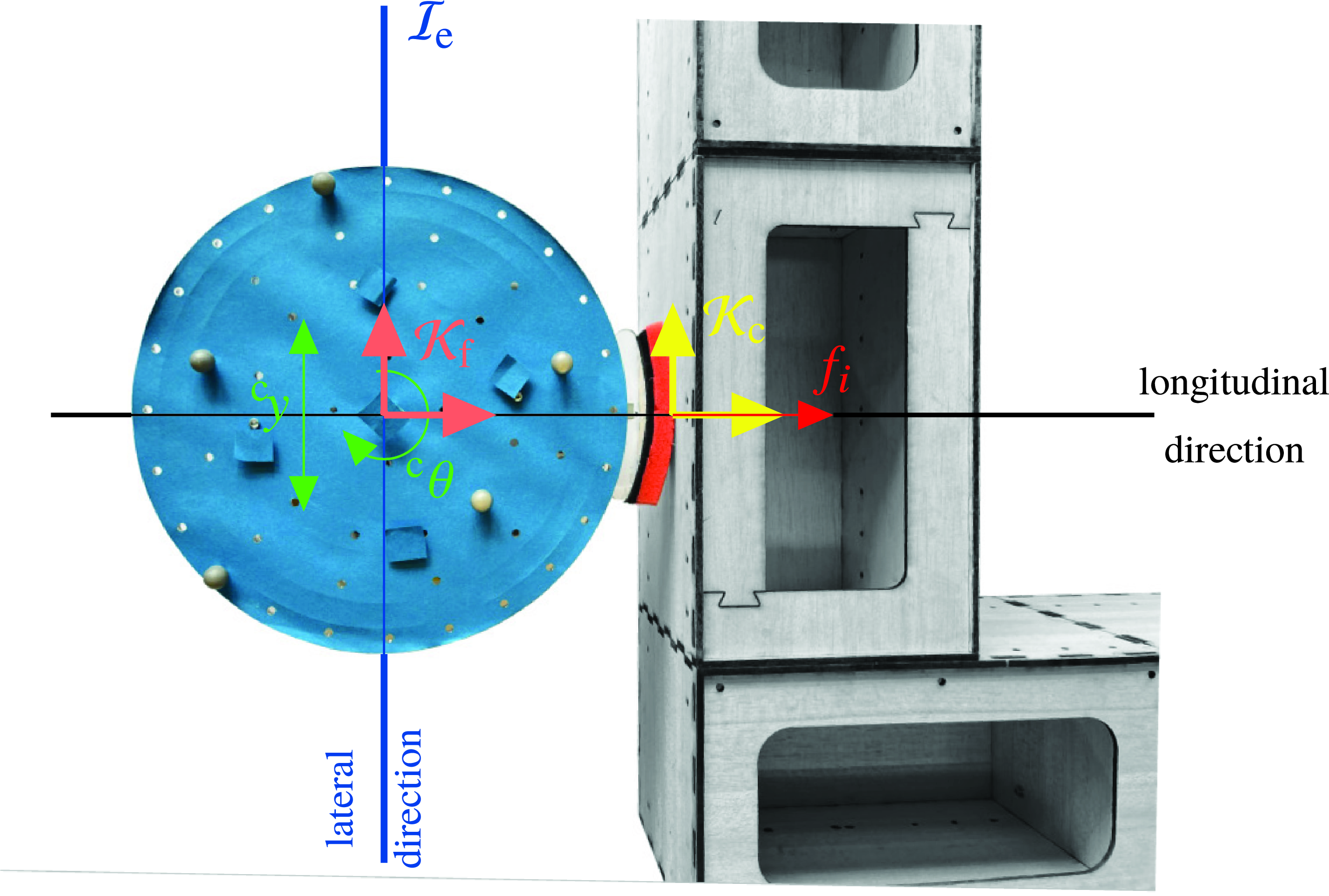
Figure 3. Employed hybrid position-force control concept.
Notably, the three control directions are equivalent to the intuitive tripartite control actions proposed in [Reference Rosenfelder, Ebel and Eberhard15]. However, having specified these control directions, it remains to control their respective control goals via lower-level onboard controllers. For this purpose, the translational motion of the robot is considered in the contact frame
 $\mathcal{K}_{\text{c}}$
such that the two planar motions, that is, longitudinal along the edge’s inner normal (
$\mathcal{K}_{\text{c}}$
such that the two planar motions, that is, longitudinal along the edge’s inner normal (
 $^{\text{c}}x$
-axis) and lateral (
$^{\text{c}}x$
-axis) and lateral (
 $^{\text{c}}y$
-axis), that is, parallel to the edge, can be handled separately, see also [Reference Rosenfelder, Ebel and Eberhard15, Sec. IV.B]. The robot’s orientation as well as the robot’s attack point (lateral control direction) at the object edge are each governed by means of an independent PI controller on position level. Crucially, in the third decoupled control direction, another underlying local PI controller governs the robot’s force exerted on the object along the
$^{\text{c}}y$
-axis), that is, parallel to the edge, can be handled separately, see also [Reference Rosenfelder, Ebel and Eberhard15, Sec. IV.B]. The robot’s orientation as well as the robot’s attack point (lateral control direction) at the object edge are each governed by means of an independent PI controller on position level. Crucially, in the third decoupled control direction, another underlying local PI controller governs the robot’s force exerted on the object along the
 $^{\text{c}}x$
-axis. For details on how the three control directions can be put into practice using the four motors of the Mecanum-wheeled mobile robot, we refer to the derivation of the employed robots’ mechanical model delineated in [Reference Ebel11, Sec. 4.2].
$^{\text{c}}x$
-axis. For details on how the three control directions can be put into practice using the four motors of the Mecanum-wheeled mobile robot, we refer to the derivation of the employed robots’ mechanical model delineated in [Reference Ebel11, Sec. 4.2].
Due to the employed hybrid position-force controller, a stable robot behavior follows with regard to its force exertion and its placement w. r. t. the object. Moreover, dealing with the scheme’s overall stability, note that a standstill command is sent to all agents if the admissible state space is left or if the object’s posture error with respect to the predefined path becomes too large. Crucially, velocity commands are realized approximately instantaneously by the robots due to negligible inertia effects, whereas friction brings the object to a halt.
It is important to stress that, in contrast to our previous work [Reference Rosenfelder, Ebel and Eberhard15, Reference Rosenfelder, Ebel, Eberhard, Petrič, Ude and Žlajpah16], the decentral determination of the force via (4) runs on the same timescale as the underlying controller since both are implemented onboard. Further, the introduced control scheme is much less complex than the distributed model predictive controller employed in the position-based setup which facilitates the onboard implementation since less computational power is necessary. Feedback between the robots is not furnished directly via communication but indirectly through the object by means of force measurements. However, this comes at the cost of an additional (although cost-efficient) hardware component in the form of the force-sensing unit displayed in Fig. 1. Crucially, as it is shown by means of the following hardware experiments, the proposed force-based control scheme retains the versatility and flexibility w. r. t. the considered object, the path to be followed, and the number of employed mobile robots. Moreover, the experiments stress the key advantage of the force-based scheme, that is, the placement of the robots and the force exertion based on actual (force-based) manipulation properties rather than solely geometric considerations.
5. Experimental results
Since all our hardware experiments are restricted to the laboratory’s working area of
 $4\,\textrm{m}$
by
$4\,\textrm{m}$
by
 $3\,\textrm{m}$
, the scenarios considered in the following are limited in size w. r. t. the considered object and the path to be followed. Moreover, up to five omnidirectional mobile robots equipped with force-sensing units are available in hardware. For the scheme’s scalability to scenarios of larger scale, we refer to the simulation setup presented in [Reference Rosenfelder, Ebel and Eberhard15], which is omitted here for the sake of brevity. However, especially in terms of present contact forces, the algorithms as well as robot and object behavior are best evaluated by means of real-world experiments.
$3\,\textrm{m}$
, the scenarios considered in the following are limited in size w. r. t. the considered object and the path to be followed. Moreover, up to five omnidirectional mobile robots equipped with force-sensing units are available in hardware. For the scheme’s scalability to scenarios of larger scale, we refer to the simulation setup presented in [Reference Rosenfelder, Ebel and Eberhard15], which is omitted here for the sake of brevity. However, especially in terms of present contact forces, the algorithms as well as robot and object behavior are best evaluated by means of real-world experiments.

Figure 4. Still images from three exemplary hardware experiments. (a) Four mobile robots transporting an object of rectangular shape along a squared path. (b) Five mobile robots transporting a +-shaped object along a sinusoidal path. (c) Five mobile robots transporting a ⊤-shaped object along an edgy path consisting of pure translation and rotation segments.
The utilized mobile robots are all of the same type with radius
 $r_{\text{r}}=0.135\,\textrm{m}$
and have a pushing capability of up to
$r_{\text{r}}=0.135\,\textrm{m}$
and have a pushing capability of up to
 $\bar{f}_i=5\,\textrm{N}$
,
$\bar{f}_i=5\,\textrm{N}$
,
 $\forall i\in \mathbb{Z}_{1:5}$
. The contact force measured by the load cell (TE Connectivity FX29) is processed by the onboard computer, a Beaglebone Blue board [28]. The board further deals with motor control, the decentralized solution of (4) using [Reference Ferreau, Kirches, Potschka, Bock and Diehl26], and the hybrid position-force controller (Section 4) running in C at a sampling rate of
$\forall i\in \mathbb{Z}_{1:5}$
. The contact force measured by the load cell (TE Connectivity FX29) is processed by the onboard computer, a Beaglebone Blue board [28]. The board further deals with motor control, the decentralized solution of (4) using [Reference Ferreau, Kirches, Potschka, Bock and Diehl26], and the hybrid position-force controller (Section 4) running in C at a sampling rate of
 $100\,\textrm{Hz}$
. Furthermore, it retrieves via a shared wireless network the robots’ and object’s postures from an external tracking system consisting of up to six Optitrack Prime 13W cameras broadcasting at a frequency of
$100\,\textrm{Hz}$
. Furthermore, it retrieves via a shared wireless network the robots’ and object’s postures from an external tracking system consisting of up to six Optitrack Prime 13W cameras broadcasting at a frequency of
 $50\,\textrm{Hz}$
. All wireless communication is handled via the LCM library [Reference Huang, Olson and Moore29]. In addition to the tracking system, this includes messages sent to the boards from the control logic implemented on external hardware in C++. In particular, the formation synthesis task (Section 3) runs asynchronously for each robot as its own program and solely communicates with the control logic (
$50\,\textrm{Hz}$
. All wireless communication is handled via the LCM library [Reference Huang, Olson and Moore29]. In addition to the tracking system, this includes messages sent to the boards from the control logic implemented on external hardware in C++. In particular, the formation synthesis task (Section 3) runs asynchronously for each robot as its own program and solely communicates with the control logic (
 $10\,\textrm{Hz}$
) (and all other robots) by means of multicast messages fitting the necessary many-to-many communication pattern. For each agent, these two programs run fully separated on external hardware (and only use communicated information) in order to avoid mounting expensive and energy-consuming computing units on the robots. The setup’s overall structure is based on the distributed software architecture developed in [Reference Ebel11] tailored for distributed robotics, and a brief description of the employed software/hardware architecture can also be found in [Reference Ebel and Eberhard17].
$10\,\textrm{Hz}$
) (and all other robots) by means of multicast messages fitting the necessary many-to-many communication pattern. For each agent, these two programs run fully separated on external hardware (and only use communicated information) in order to avoid mounting expensive and energy-consuming computing units on the robots. The setup’s overall structure is based on the distributed software architecture developed in [Reference Ebel11] tailored for distributed robotics, and a brief description of the employed software/hardware architecture can also be found in [Reference Ebel and Eberhard17].
The objects to be manipulated are made of a modular design consisting of multiple individual wooden boxes sliding on the planar ground, where each box weighs
 $120\,\textrm{g}$
and is of size
$120\,\textrm{g}$
and is of size
 $280\,\textrm{mm}\times 160\,\textrm{mm}$
. It is the overall goal that the robots cooperatively push and rotate the object along a predefined path, where the desired path’s planar projection is indicated by a dashed black line in all following figures. Crucially, the desired translational force
$280\,\textrm{mm}\times 160\,\textrm{mm}$
. It is the overall goal that the robots cooperatively push and rotate the object along a predefined path, where the desired path’s planar projection is indicated by a dashed black line in all following figures. Crucially, the desired translational force
 $\boldsymbol{f}_{\text{t},\text{des}}$
and the torque
$\boldsymbol{f}_{\text{t},\text{des}}$
and the torque
 $\tau _{\text{des}}$
the robots should exert are chosen proportional to the current deviation retrieved from the path parametrization, but upper bounded if a certain limit is exceeded.
$\tau _{\text{des}}$
the robots should exert are chosen proportional to the current deviation retrieved from the path parametrization, but upper bounded if a certain limit is exceeded.
At first, three scenarios are considered in which four or five mobile robots shall transport objects of different size and shape along distinct paths. Note that in the subsequently discussed illustrations, the robots’ orientation, that is, the direction of the unilateral force-sensing unit, is indicated by means of a white rectangle. Moreover, the actually exerted force at the given time instant is highlighted by means of a red rectangle overlaying the white one, where the area of the overlay is proportional to the force so that full overlay corresponds to the robot’s pushing limit
 $\bar{f}_i$
. The hitherto covered path of the object’s center of mass is depicted as an orange line.
$\bar{f}_i$
. The hitherto covered path of the object’s center of mass is depicted as an orange line.
In the first scenario,
 $N=4$
robots shall push a rectangular box without rotating it. Crucially, at least two robots are needed to cooperatively exert the necessary force in the primary pushing direction, see Fig. 4(a). Therefore, the object is pushed along each edge of the square by similar formations, whereas at the path’s corners reorganization is necessary to adapt for the abrupt change in the translational direction. Importantly, the placement of sufficiently many robots along the same edge is intrinsically covered by the closed-set formulation since an additional robot can be interpreted as another generator which significantly enlarges the zonotope in the corresponding direction. Note that this approach is only practicable if the acting forces can be measured, yielding the main advantage of the force-based setup compared to the solely geometric consideration. This can also be seen in the second scenario where five robots shall transport a
$N=4$
robots shall push a rectangular box without rotating it. Crucially, at least two robots are needed to cooperatively exert the necessary force in the primary pushing direction, see Fig. 4(a). Therefore, the object is pushed along each edge of the square by similar formations, whereas at the path’s corners reorganization is necessary to adapt for the abrupt change in the translational direction. Importantly, the placement of sufficiently many robots along the same edge is intrinsically covered by the closed-set formulation since an additional robot can be interpreted as another generator which significantly enlarges the zonotope in the corresponding direction. Note that this approach is only practicable if the acting forces can be measured, yielding the main advantage of the force-based setup compared to the solely geometric consideration. This can also be seen in the second scenario where five robots shall transport a
 $+$
-shaped object along a sinusoidal path, with the same edge facing the translational direction such that simultaneous translation and rotation is required, see Fig. 4(b). Analogously, two robots are placed along one edge if the primal manipulation objective is to translate the object in the corresponding inner normal direction of the edge, see the second and fourth still of Fig. 4(b). Since the scheme’s overall characteristics are best witnessed in motion, videos of all scenarios presented in this paper can be found in [Reference Rosenfelder, Ebel and Eberhard20]. Further, it is worth noting that the illustrations given in Fig. 2(a) and (b) are visualizations of the second scenario’s scenery at
$+$
-shaped object along a sinusoidal path, with the same edge facing the translational direction such that simultaneous translation and rotation is required, see Fig. 4(b). Analogously, two robots are placed along one edge if the primal manipulation objective is to translate the object in the corresponding inner normal direction of the edge, see the second and fourth still of Fig. 4(b). Since the scheme’s overall characteristics are best witnessed in motion, videos of all scenarios presented in this paper can be found in [Reference Rosenfelder, Ebel and Eberhard20]. Further, it is worth noting that the illustrations given in Fig. 2(a) and (b) are visualizations of the second scenario’s scenery at
 $t=20\,\textrm{s}$
, cf. Fig 4(b). In a third scenario, five robots shall transport a
$t=20\,\textrm{s}$
, cf. Fig 4(b). In a third scenario, five robots shall transport a
 $\top$
-shaped object along an edgy path. However, in contrast to the first scenario, the path does not only contain segments of pure translation, but also pure rotation segments, see the third still of Fig. 4(c) which was taken after
$\top$
-shaped object along an edgy path. However, in contrast to the first scenario, the path does not only contain segments of pure translation, but also pure rotation segments, see the third still of Fig. 4(c) which was taken after
 $t=100\,\textrm{s}$
. Hence, the presented scenarios do not only consider objects of very different shape but also paths subject to simultaneous translation and rotation as well as pure translational and rotational segments, respectively.
$t=100\,\textrm{s}$
. Hence, the presented scenarios do not only consider objects of very different shape but also paths subject to simultaneous translation and rotation as well as pure translational and rotational segments, respectively.
In addition to the qualitative performance indicated in Fig. 4 and [Reference Rosenfelder, Ebel and Eberhard20], Fig. 5 quantitatively emphasizes the proposed scheme’s quality for the aforementioned three scenarios. Particularly, the object’s positional path tracking error is presented, which is determined by the Euclidean distance of the object’s center of mass to the closest point on the predefined path in each time step. This path tracking error is less than
 $4\,\textrm{cm}$
for all scenarios and all time instants where the overall lengths of the paths read
$4\,\textrm{cm}$
for all scenarios and all time instants where the overall lengths of the paths read
 $1.5\,\textrm{m}$
,
$1.5\,\textrm{m}$
,
 $1.25\,\textrm{m}$
, and
$1.25\,\textrm{m}$
, and
 $2.14\,\textrm{m}$
, respectively. Moreover, the maximum and median errors evaluate for the three considered scenarios to
$2.14\,\textrm{m}$
, respectively. Moreover, the maximum and median errors evaluate for the three considered scenarios to
 $2.9\,\textrm{cm}$
,
$2.9\,\textrm{cm}$
,
 $4.0\,\textrm{cm}$
, and
$4.0\,\textrm{cm}$
, and
 $3.3\,\textrm{cm}$
as well as
$3.3\,\textrm{cm}$
as well as
 $0.9\,\textrm{cm}$
,
$0.9\,\textrm{cm}$
,
 $1.5\,\textrm{cm}$
, and
$1.5\,\textrm{cm}$
, and
 $0.8\,\textrm{cm}$
, respectively, using the ordering of the subfigures of Fig. 4. Note that the median error is influenced by the initial, manual placement of the object and that the depicted errors’ noisiness stems from the motion capture system, which was operated at a recording frequency of
$0.8\,\textrm{cm}$
, respectively, using the ordering of the subfigures of Fig. 4. Note that the median error is influenced by the initial, manual placement of the object and that the depicted errors’ noisiness stems from the motion capture system, which was operated at a recording frequency of
 $50\,\textrm{Hz}$
.
$50\,\textrm{Hz}$
.

Figure 5. Positional path tracking errors for the hardware experiments depicted in Fig. 4.
Having indicated the scheme’s versatility, its self-reliant adaption to very different scenarios, and its path following preciseness, the following consideration aims at exemplifying the robustness of the proposed force-based approach and indicating the performance of the underlying explicit force control. To this end, three robots shall transport an
 $\llcorner$
-shaped object along a circular path with a diameter of
$\llcorner$
-shaped object along a circular path with a diameter of
 $0.8\,\textrm{m}$
. Figure 6 (left) shows this desired path as well as the resulting paths for ten different runs, where the latter are plotted on top of each other with reduced opacity. As it can be seen there, for all considered runs, the setup successfully solved the task with good accuracy. Moreover, the robots’ resulting force trajectories are depicted in Fig. 6 for one exemplary run. Note that for this run, two specific postures of the object are illustrated along the path, namely at the beginning (time instant
$0.8\,\textrm{m}$
. Figure 6 (left) shows this desired path as well as the resulting paths for ten different runs, where the latter are plotted on top of each other with reduced opacity. As it can be seen there, for all considered runs, the setup successfully solved the task with good accuracy. Moreover, the robots’ resulting force trajectories are depicted in Fig. 6 for one exemplary run. Note that for this run, two specific postures of the object are illustrated along the path, namely at the beginning (time instant
 $t_0$
) and, with reduced opacity, after half of the path has been covered (
$t_0$
) and, with reduced opacity, after half of the path has been covered (
 $t_\pi$
). The robots’ colors shown in the picture correspond to the respective color of the displayed force trajectories. The desired individual pushing forces of the robots are shown in red. It can be seen that the actual exerted forces follow the desired ones very well highlighting the advantages of the proposed control design acting on a fast timescale using the onboard hybrid controller. Note that the heavily oscillating interaction force, which is measured onboard and plotted in Fig. 3 at a sampling time of
$t_\pi$
). The robots’ colors shown in the picture correspond to the respective color of the displayed force trajectories. The desired individual pushing forces of the robots are shown in red. It can be seen that the actual exerted forces follow the desired ones very well highlighting the advantages of the proposed control design acting on a fast timescale using the onboard hybrid controller. Note that the heavily oscillating interaction force, which is measured onboard and plotted in Fig. 3 at a sampling time of
 $10\,\textrm{ms}$
, is typical for contact forces, especially if the contact partners are in motion. Additionally, the measured interaction forces of the robots averaged over a moving window of
$10\,\textrm{ms}$
, is typical for contact forces, especially if the contact partners are in motion. Additionally, the measured interaction forces of the robots averaged over a moving window of
 $250\,\textrm{ms}$
are shown in black color in the respective plots of Fig. 6. As can be seen, the smoothened measurement tracks the desired force very well, stressing the performance of the underlying highly responsive controller. Importantly, the onboard calculation of the desired force via the quadratic program (4) and the corresponding underlying control is a significant advancement compared to [Reference Rosenfelder, Ebel, Eberhard, Petrič, Ude and Žlajpah16] explaining the beneficial performance of the employed force controller, also in comparison to our previous work, compare [Reference Rosenfelder, Ebel, Eberhard, Petrič, Ude and Žlajpah16, Fig. 4]. Notably, the underlying controllers do not only govern the exerted force but also the relative position and orientation of the robots with respect to their desired contact points. For the previous example, during 95% of the time the hybrid position-force controller has been active, the absolute orientation errors of the robots were less than
$250\,\textrm{ms}$
are shown in black color in the respective plots of Fig. 6. As can be seen, the smoothened measurement tracks the desired force very well, stressing the performance of the underlying highly responsive controller. Importantly, the onboard calculation of the desired force via the quadratic program (4) and the corresponding underlying control is a significant advancement compared to [Reference Rosenfelder, Ebel, Eberhard, Petrič, Ude and Žlajpah16] explaining the beneficial performance of the employed force controller, also in comparison to our previous work, compare [Reference Rosenfelder, Ebel, Eberhard, Petrič, Ude and Žlajpah16, Fig. 4]. Notably, the underlying controllers do not only govern the exerted force but also the relative position and orientation of the robots with respect to their desired contact points. For the previous example, during 95% of the time the hybrid position-force controller has been active, the absolute orientation errors of the robots were less than
 $0.548\,\textrm{deg}$
,
$0.548\,\textrm{deg}$
,
 $0.387\,\textrm{deg}$
, and
$0.387\,\textrm{deg}$
, and
 $0.751\,\textrm{deg}$
, respectively, whereas the maximum absolute orientation errors were
$0.751\,\textrm{deg}$
, respectively, whereas the maximum absolute orientation errors were
 $1.078\,\textrm{deg}$
,
$1.078\,\textrm{deg}$
,
 $0.754\,\textrm{deg}$
, and
$0.754\,\textrm{deg}$
, and
 $0.956\,\textrm{deg}$
, respectively, exemplifying the functionality of the proposed hybrid controller also on positional level. Consequently, not only the robots’ individual desired pushing forces are tracked precisely, cf. Fig. 6, but also the overall desired force acting on the object.
$0.956\,\textrm{deg}$
, respectively, exemplifying the functionality of the proposed hybrid controller also on positional level. Consequently, not only the robots’ individual desired pushing forces are tracked precisely, cf. Fig. 6, but also the overall desired force acting on the object.

Figure 6. Left: Overlaid results of ten exemplary experiments in which three mobile robots shall transport an
 $\llcorner$
-shaped object along a circular path. Right: Trajectories of the measured contact forces (color corresponds to the robots’ colors on the left) and the corresponding desired force (in red color) for each robot.
$\llcorner$
-shaped object along a circular path. Right: Trajectories of the measured contact forces (color corresponds to the robots’ colors on the left) and the corresponding desired force (in red color) for each robot.
Moreover, the desired interaction forces do not exceed the limit of
 $\bar{f}_{i}=5\,\textrm{N}$
at any time, see Fig. 6, encouraging safe application of the actually exerted forces in order to prevent damages. Further, one clearly sees the scheme’s natural feedback while the robots approach the object and the different convergence levels as robot two and three wait for robot one to be in contact with the object, that is,
$\bar{f}_{i}=5\,\textrm{N}$
at any time, see Fig. 6, encouraging safe application of the actually exerted forces in order to prevent damages. Further, one clearly sees the scheme’s natural feedback while the robots approach the object and the different convergence levels as robot two and three wait for robot one to be in contact with the object, that is,
 $f_{2,\text{des}}(t)=f_{3,\text{des}}(t)=0$
for all
$f_{2,\text{des}}(t)=f_{3,\text{des}}(t)=0$
for all
 $t\in [0,t_0)$
. Note that the force sensors have not been calibrated right before the run such that there is a small static offset in the force measurements implying
$t\in [0,t_0)$
. Note that the force sensors have not been calibrated right before the run such that there is a small static offset in the force measurements implying
 $f_i\lt 0$
if no contact force is present. It is worth stressing that in the presented real-world experiments, overcoming the Coulomb friction constitutes the major task for the controller. However, once the initial movement is anticipated and the object slides, the proposed decentralized hybrid position-force controller is able to precisely govern the desired force, see Fig. 6.
$f_i\lt 0$
if no contact force is present. It is worth stressing that in the presented real-world experiments, overcoming the Coulomb friction constitutes the major task for the controller. However, once the initial movement is anticipated and the object slides, the proposed decentralized hybrid position-force controller is able to precisely govern the desired force, see Fig. 6.
6. Conclusions and outlook
The present paper establishes a force-based scheme to cooperatively transport a broad class of objects using mobile robots with non-prehensile contacts. Crucially, to the best knowledge of the authors, this task is novelly solved by explicitly taking into account, measuring, and controlling the interaction forces between the robots and the object. This consideration allows to describe the actual manipulation capability of the overall configuration more precisely as a closed set in the form of a zonotope. This makes it possible to respect the robots’ force limits and leads to an efficient usage of the robots’ resources compared to position-based schemes. Further, an intuitive optimization problem is formulated to retrieve desirable individual forces. Due to the computationally cost-efficient formulation as a quadratic program, this optimization problem can be run onboard within the decentralized hybrid position-force controller needing less computational power in contrast to the distributed predictive controller used within our previous position-based approach, which already was probably the most versatile of its kind. These advantages are witnessed by means of the presented hardware experiments, showing that the versatility stemming from the tailored distributed software architecture, which has been developed in [Reference Ebel11] for the position-based scheme, is retained also for the presented force-based approach.
However, the force-based scheme also suffers from some downsides. Since the contact force can only be measured along one axis, the approach is not able to utilize two contact points per robot to manipulate the object. In our previous position-based approach, see, for example, [Reference Ebel and Eberhard21, Fig. 12], these attacking points in concave corners have been proven to be very beneficial since, from the manipulation space perspective from Section 3, they yield two different generators which are linearly independent. Moreover, due to stick-slip-effects at the object, it is not always trivial what absolute value of the desired generalized force
 $\boldsymbol{f}_{\text{d}}$
is the most expedient for the current manipulation objective. In our opinion, this is a remaining key factor limiting the overall performance and, thus, a current field of interest.
$\boldsymbol{f}_{\text{d}}$
is the most expedient for the current manipulation objective. In our opinion, this is a remaining key factor limiting the overall performance and, thus, a current field of interest.
Beyond the presented scenario dealing with omnidirectional mobile robots, it stands to reason to investigate whether the proposed scheme can be extended to the more popular class of differential drive mobile robots. The task has already been accomplished on position level [Reference Ebel, Rosenfelder and Eberhard30], where the formation finding problem [Reference Ebel, Fahse, Rosenfelder and Eberhard24] tailored for the present non-holonomic constraints has been formulated based on second-order differential equations using Jourdain’s principle. Therein, the overall force a differential drive robot exerts on the object is divided into a reaction force following from the non-holonomic constraint and an actively exerted force which, in the future, could be measured and governed by means of the presented force-sensing unit. However, detailed research is necessary whether the proposed hybrid controller can be utilized for this class of robots since a decoupling of the directions is impeded due to the non-holonomic constraint [Reference Rosenfelder, Ebel, Krauspenhaar and Eberhard31]. Further, the proposed force-based scheme paves the way to also manipulate deformable objects which is subject to our current field research.
Author contributions
Mario Rosenfelder and Henrik Ebel were responsible for the basic concepts. Mario Rosenfelder carried out the experiments and performed analyses of the data. Mario Rosenfelder and Henrik Ebel wrote the article and developed software and hardware. Mario Rosenfelder, Henrik Ebel, and Peter Eberhard discussed the results. Henrik Ebel and Peter Eberhard did proofreading.
Financial support
This work was supported by the Deutsche Forschungsgemeinschaft (DFG, German Research Foundation) under Grants 501890093 (SPP 2353) and 433183605, and through Germany’s Excellence Strategy (Project PN4-4 “Learning from Data - Predictive Control in Adaptive Multi-Agent Scenarios”) under Grant EXC 2075-390740016.
Competing interests
The authors declare no competing interests exist.
Ethical approval
Not applicable.


 Open access