


1 Introduction
Lasers with 2 μm waveband have been widely used in various technical fields, including medical laser application[Reference Antipov, Zakharov, Fedorov, Shakhova, Prodanets, Snopova, Sharkov and Sroka1], remote sensing[Reference Carrig2,Reference Wagener, Demma, Kmetec and Kubo3] , and 3–5 μm nonlinear frequency conversion as the pump source[Reference Liu, Mi, Yang, Wei, Li, Yao, Yang, Dai, Duan, Tian and Ju4], owing to their excellent characteristics of being located in the atmospheric window, strong absorption band of water, and safety zone of human eyes[Reference Liu, Mi, Yang, Wei, Li, Yao, Yang, Dai, Duan, Tian and Ju4–Reference Berrou, Collett, Morris and Esser6]. At room temperature, a laser crystal doped with trivalent rare earth holmium (Ho) ions has a long upper-state lifetime and a large emission cross section, and thus is an efficient 2 μm solid laser material. As excellent pumping sources for Ho lasers, thulium-doped materials have several attractive properties of light generation, including a wide emission bandwidth, long lifetime upper laser level, and high quantum efficiency potential owing to the two-to-one cross-relaxation process[Reference Budni, Lemons, Mosto and Chicklis7,Reference Duan, Cai, Ding, Dai and Zhao8] . As far as Tm:YLF material is concerned, it has a strong absorption near 791 nm[Reference Walsh, Barnes, Petros, Yu and Singh9], which is suitable for laser diode (LD) pumping. The cross section at 1908 nm in the direction of σ polarization is the largest[Reference Walsh, Barnes, Petros, Yu and Singh9], which exactly overlaps with the absorption spectrum of Ho:YAG[Reference Budni, Lemons, Mosto and Chicklis7]. However, the absorption spectrum of Ho:YAG is relatively narrow[Reference Li, Chen, Liu, Wu, Dong and Jin10], and there are a lot of H2O absorption lines in the near-infrared spectral region[Reference Gordon, Rothman, Hill, Kochanov, Tan, Bernath, Birk, Boudon, Campargue, Chance, Drouin, Flaud, Gamache, Hodges, Jacquemart, Perevalov, Perrin, Shine, Smith, Tennyson, Toon, Tran, Tyuterev, Barbe, Császár, Devi, Furtenbacher, Harrison, Hartmann, Jolly, Johnson, Karman, Kleiner, Kyuberis, Loos, Lyulin, Massie, Mikhailenko, Moazzen-Ahmadi, Müller, Naumenko, Nikitin, Polyansky, Rey, Rotger, Sharpe, Sung, Starikova, Tashkun, Auwera, Wagner, Wilzewski, Wcisło, Yu and Zak11]. Therefore, it is necessary to limit the output linewidth of Tm:YLF laser.
A reflecting volume Bragg grating (VBG) is a kind of narrow-band-pass filter element based on the Bragg condition. It can be used to replace the laser resonator mirror of Tm:YLF laser to achieve narrow-linewidth laser output[Reference Dergachev, Moulton, Smirnov and Glebov12–Reference Strauss, Esser, King and Maweza14]. However, the minute absorption of VBG as a cavity end mirror can cause some adverse effects, including the change of spatial period and refractive index, the decrease of diffraction efficiency, and surface deformation, which will cause changes in laser performance[Reference Waritanant and Chung15,Reference Tjornhammar, Jacobsson, Pasiskevicius and Laurell16] , especially the obvious wavelength shift. Owing to the existence of mass water absorption lines in the near-infrared spectral region[Reference Gordon, Rothman, Hill, Kochanov, Tan, Bernath, Birk, Boudon, Campargue, Chance, Drouin, Flaud, Gamache, Hodges, Jacquemart, Perevalov, Perrin, Shine, Smith, Tennyson, Toon, Tran, Tyuterev, Barbe, Császár, Devi, Furtenbacher, Harrison, Hartmann, Jolly, Johnson, Karman, Kleiner, Kyuberis, Loos, Lyulin, Massie, Mikhailenko, Moazzen-Ahmadi, Müller, Naumenko, Nikitin, Polyansky, Rey, Rotger, Sharpe, Sung, Starikova, Tashkun, Auwera, Wagner, Wilzewski, Wcisło, Yu and Zak11], the shift is very unfriendly for Tm:YLF laser, especially at the output power level of hundreds of watts. From this point of view, effective heat dissipation for VBG is recommended to prevent its performance degradation in this experiment.
At present, there are few reports about Tm:YLF lasers with an output power level of 200 W, but the previous reports are based on Tm crystals dual-end-pumped by LD stacks, where the beam quality factor M 2 in one direction is very poor. In 2013, Li et al. reported that a 200 W Innoslab Tm:YLF laser output had a strong elliptical beam shape with a Gaussian distribution along the semi-minor axis and a top-hat-like distribution beam shape along the semi-major axis[Reference Li, Yang, Meissner, Hoefer and Hoffmann17]. In 2019, Mao and Wang reported a 213 W Tm:YLF Innoslab wavelength-selected laser, and the corresponding beam quality factors were M 2 x = 520 and M 2 y = 2.1 at only 120 W[Reference Mao and Wang18]. Based on the previous reports, the beam quality is very poor in one direction and difficult to control, which has badly limited its application.
In this paper, a 202 W Tm:YLF laser with relatively good beam quality and narrow linewidth near 1908 nm was demonstrated by using two crystals in series and a dual-end-pumped structure for each crystal. To the best of the authors’ knowledge, this is the first report on such high-power output with VBG as an output coupler for a Tm:YLF slab laser. To suppress the wavelength shift to the water absorption line near 1908.9 nm, the active heat dissipation methods were used to cool the VBG, including microchannel cooling and temperature control with a thermoelectric cooler (TEC). The results show that active cooling can effectively restrain the growth rate of the laser output wavelength. Without active cooling, the laser wavelength was 1908.8 nm at 160 W; with TEC, the laser wavelength was 1908.64 nm at 201 W; with microchannel cooling, the laser wavelength was 1908.5 nm at 202 W. In this way, the Tm:YLF laser was operated at 1908.5 nm with linewidth (full width at half maximum, FWHM) 0.57 nm. Under an incident pump power of 553 W, the maximum continuous wave (CW) output power of 202 W at 1908.5 nm was obtained, corresponding to the slope efficiency of 39.7% and optical-to-optical conversion efficiency of 36.5%, where the beam quality factors M 2 were 2.3 and 4.0 for horizontal and vertical directions, respectively.
2 Experimental setup
The experimental setup of the Tm:YLF slab laser is shown in Figure 1. A double-crystal series and a dual-end-pump configuration were utilized in this experiment. The four pump lasers were 150 W fiber-coupled LDs with core diameter of 400 μm, numerical aperture of 0.2, and central wavelength of 792 nm at the highest power. The radiation of each LD was coupled into the laser crystal by the same focusing optical system composed of two spherical lenses with focal lengths f 1 = 13 mm and f 2 = 55 mm, generating a pump beam diameter of about 1.7 mm within the laser crystals. Between f 1 and f 2, a 45° high-reflection (HR) mirror M2 was used to change the direction of the 792 nm radiation. In this work, two 2 at.%, 2 mm × 6 mm × 40 mm and a-cut Tm:YLF crystals were wrapped with indium foil and mounted in copper blocks cooled by water at a temperature of 290 K. The two crystals were connected in series in the resonant cavity. The whole cavity consisted of four 45° dichroic mirrors M1, a VBG, and a reflector M3. One side of the mirror M1 was coated with 792 nm anti-reflection coating, the other side was coated with HR material at 1908–2090 nm (R > 97%) and highly transmitting at 792 nm. The mirror M3 was a concave mirror with a radius of curvature of 200 mm and HR coated at 1.9 μm (R > 99.7%). As the output coupler of the laser, the VBG had a clear aperture of 3 mm × 4 mm and a thickness of 2.4 mm and its diffraction efficiency was about 58.4% at 1907.3 nm, whose spectral selectivity was less than 0.7 nm. It was wrapped in indium foil and mounted on a copper heat sink. In addition, the physical cavity length of the Tm:YLF laser was 230 mm.
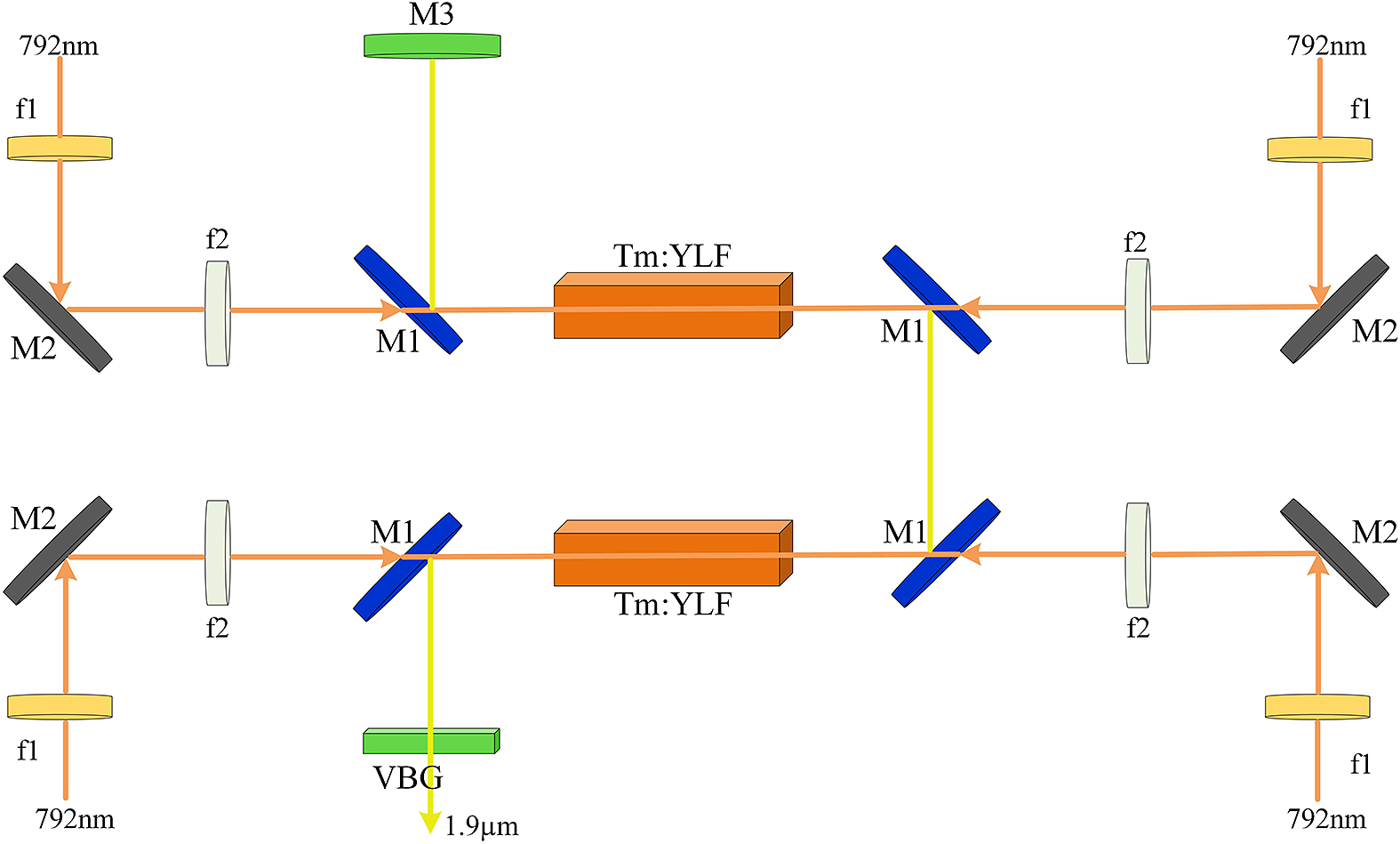
Figure 1 Diagrammatic sketch of the experimental setup.
3 Results and discussion
First, without active cooling, the emission wavelength shifted from 1907.3 to 1908.8 nm and the corresponding volume grating temperature increased from 302 to 391 K, when the output power was increased from 7 to 160 W, as shown in Figure 3(a). The temperature was measured three times and averaged at the same output power, recorded by a temperature-measuring infrared thermal imager (DALI LT7-P). The wavelength was shifted 1.5 nm. This meant that if we continued to increase the output power of the laser, its wavelength was likely to drift to the water absorption line near 1908.97 nm as shown in Figure 2, which would cause damage to the laser. The reason for the wavelength shift is that VBG has a small absorption coefficient (less than 0.01 cm–1 [Reference Efimov, Glebov, Smirnov and Glebova19]) for 1.9 μm laser, and the absorbed energy is converted into heat, which causes a temperature rise and distortion especially in high-flux laser irradiation.
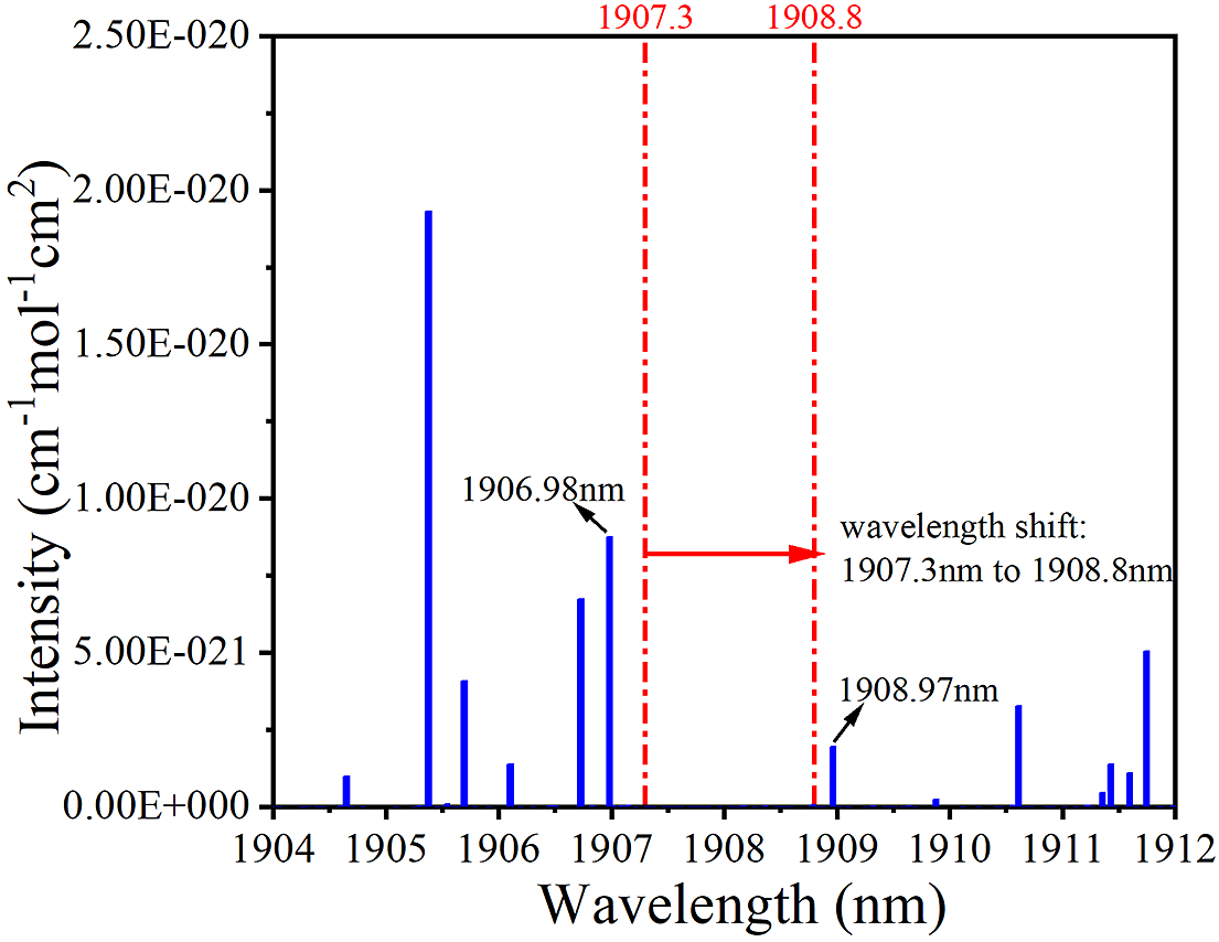
Figure 2 Water absorption spectrum near 1908 nm (plotted using HITRAN data[Reference Gordon, Rothman, Hill, Kochanov, Tan, Bernath, Birk, Boudon, Campargue, Chance, Drouin, Flaud, Gamache, Hodges, Jacquemart, Perevalov, Perrin, Shine, Smith, Tennyson, Toon, Tran, Tyuterev, Barbe, Császár, Devi, Furtenbacher, Harrison, Hartmann, Jolly, Johnson, Karman, Kleiner, Kyuberis, Loos, Lyulin, Massie, Mikhailenko, Moazzen-Ahmadi, Müller, Naumenko, Nikitin, Polyansky, Rey, Rotger, Sharpe, Sung, Starikova, Tashkun, Auwera, Wagner, Wilzewski, Wcisło, Yu and Zak11]) and laser wavelength shift.
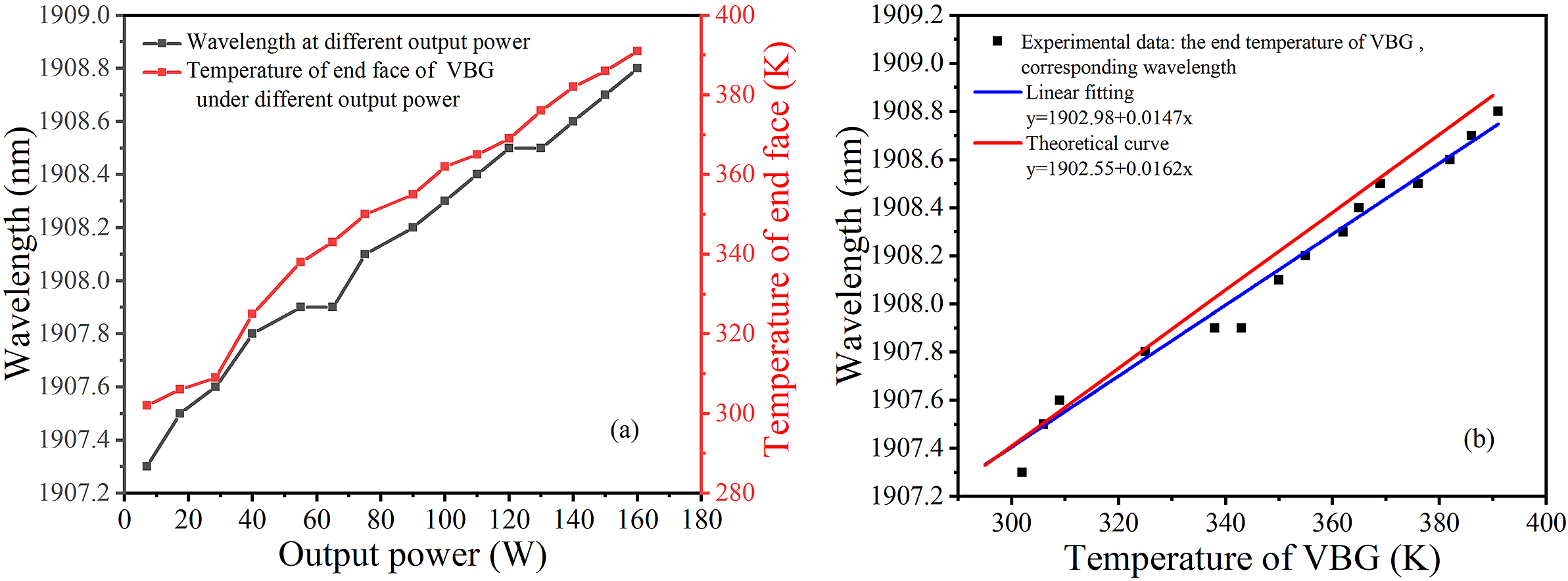
Figure 3 Dependence of the laser wavelength on temperature without active cooling in the VBG: (a) wavelength at different output power and corresponding temperature under different output power; (b) fitting of the relationship between wavelength and temperature, and corresponding theoretical curve.
Owing to the change in spatial period caused by the non-uniform thermal expansion and the change in refractive index caused by the thermal dispersion coefficient, some wavelength components of the incident laser deviate from the Bragg condition,
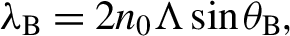 \begin{align}{\lambda}_{\mathrm{B}}=2{n}_0\Lambda \sin {\theta}_{\mathrm{B}},\end{align}
where λB is the Bragg wavelength, n
0 is the refractive index, and
 $\Lambda$
is the grating period[Reference Zhang, Feng, Xiong, Zou and Yuan20]. The influence of temperature change on Bragg wavelength can be analyzed by the derivative of the Bragg condition with respect to temperature T at normal incidence,
$\Lambda$
is the grating period[Reference Zhang, Feng, Xiong, Zou and Yuan20]. The influence of temperature change on Bragg wavelength can be analyzed by the derivative of the Bragg condition with respect to temperature T at normal incidence,
 \begin{align}\frac{\mathrm{d}{\lambda}_{\mathrm{B}}}{\mathrm{d}T}=2\frac{\mathrm{d}{n}_0}{\mathrm{d}T}\Lambda +2\frac{\mathrm{d}\Lambda}{\mathrm{d}T}{n}_0={\lambda}_{\mathrm{B}}\cdot \left(\frac{1}{n}\frac{\mathrm{d}{n}_0}{\mathrm{d}T}+\rho \right).\end{align}
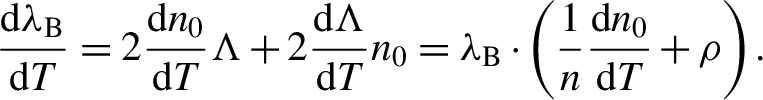
In Equation (2), ρ is the thermal expansion coefficient and dn
0
/dT is the thermal dispersion coefficient. For PTR glass, the values are
 $\rho =8.5\times {10}^{-6}$
K–1
[Reference Efimov, Glebov, Smirnov and Glebova19] and
$\rho =8.5\times {10}^{-6}$
K–1
[Reference Efimov, Glebov, Smirnov and Glebova19] and
 $\mathrm{d}{n}_0/\mathrm{d}T=5\times {10}^{-8}$
K–1
[Reference Zediker, Venus, Sevian, Smirnov and Glebov21]. As the thermal dispersion coefficient is two orders of magnitude smaller than the thermal expansion coefficient, the influence of thermal dispersion coefficient can be ignored. Hence, Equation (2) can be further simplified as follows:
$\mathrm{d}{n}_0/\mathrm{d}T=5\times {10}^{-8}$
K–1
[Reference Zediker, Venus, Sevian, Smirnov and Glebov21]. As the thermal dispersion coefficient is two orders of magnitude smaller than the thermal expansion coefficient, the influence of thermal dispersion coefficient can be ignored. Hence, Equation (2) can be further simplified as follows:
 \begin{align}\frac{\mathrm{d}{\lambda}_{\mathrm{B}}}{\mathrm{d}T}={\lambda}_{\mathrm{B}}\cdot \rho .\end{align}
The general solution of Equation (3) is
 \begin{align}{\lambda}_{\mathrm{B}}={A}_{\lambda_{\mathrm{B}0}}\cdot {e}^{\rho T}.\end{align}
Here
 ${A}_{\lambda_{\mathrm{B}0}}$
is a constant, which depends on a VBG with a given Bragg wavelength. As ρ is very small, Equation (4) can be approximated by the first-order McLaughlin approximation,
${A}_{\lambda_{\mathrm{B}0}}$
is a constant, which depends on a VBG with a given Bragg wavelength. As ρ is very small, Equation (4) can be approximated by the first-order McLaughlin approximation,
 \begin{align}{\lambda}_{\mathrm{B}}={A}_{\lambda_{\mathrm{B}0}}+{A}_{\lambda_{\mathrm{B}0}}\rho T.\end{align}
Equation (5) shows that the dependence of Bragg wavelength on temperature can be approximately linear, described by the slope of the expression with dλB
/dT. We assume that the Bragg wavelength of the VBG is 1907.3 nm at 293 K to calculate the dependence. The constant
 ${A}_{\lambda_{\mathrm{B}0}}$
is about 1902.55 nm and dλB
/dT is roughly 0.0162 nm⋅K–1, which is close to the actual values of 1902.98 nm and 0.0147 nm⋅K–1 acquired by fitting the experimental data, as shown in Figure 3(b). We can also calculate the wavelength shift of 1.44 nm from 302 to 391 K, which is basically consistent with the experimental value 1.50 nm. Therefore, in order to prevent water absorption damage to the laser, effective measures must be taken to restrain the laser wavelength shift caused by the increase of VBG temperature.
${A}_{\lambda_{\mathrm{B}0}}$
is about 1902.55 nm and dλB
/dT is roughly 0.0162 nm⋅K–1, which is close to the actual values of 1902.98 nm and 0.0147 nm⋅K–1 acquired by fitting the experimental data, as shown in Figure 3(b). We can also calculate the wavelength shift of 1.44 nm from 302 to 391 K, which is basically consistent with the experimental value 1.50 nm. Therefore, in order to prevent water absorption damage to the laser, effective measures must be taken to restrain the laser wavelength shift caused by the increase of VBG temperature.
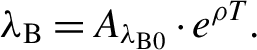
The output characteristics with different heat dissipation methods of the VBG are compared in Figure 4. There were two active cooling methods, the first was a microchannel cooler and the second was a TEC. The ambient temperature of the VBG was controlled at 290 K with these two methods. As shown in Figure 4(a), the slope efficiencies under different conditions were 39.7%, 38.2%, and 39.9% and the corresponding thresholds were 54.7, 51.5, and 57.6 W, respectively. According to the existing literature, it can be shown that a VBG used as a cavity end mirror of laser has the thermal lensing effect[Reference Jelger, Wang, Sahu, Laurell and Clarkson22] and causes reduction of diffraction efficiency[Reference Waritanant and Chung15,Reference Tjornhammar, Jacobsson, Pasiskevicius and Laurell16,Reference Zhang, Feng, Xiong, Zou and Yuan20] , which leads to the change of the mode volume and the reflectivity of the VBG, thus changing the output characteristics of the laser. Hence, after the active cooling, the light output threshold decreased slightly, and the efficiency had a slight change. In Figure 4(a), it should be noted that the total incident pump power was different in the two cases: less than 465 W without active cooling and 553 W under active cooling. Figure 4(b) shows that these methods successfully limit the growth rate of laser wavelength; especially the microchannel cooler is more effective. The corresponding wavelengths at 30 and 202 W were 1907.50 and 1908.51 nm, respectively, leading to a shift of 1.01 nm, which was much better than that without active cooling. Meanwhile, the TEC was also useful, but the effect was not as pronounced as that of microchannel cooler. The wavelength shifted by 1.1 nm from 1907.54 nm at 30 W to 1908.64 nm at 201 W. In addition, the maximum temperature of the VBG was 389 K at 201 W.
Figure 4 Comparison of CW laser performance, including (a) output power and (b) wavelength under different heat dissipation methods for the VBG.
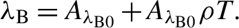
The 10/90 knife edge method was used to measure the spot radius at different positions, and the beam quality factor M 2 was further obtained by fitting the spot change curve. As shown in Figure 5, the beam quality factor M 2 was compared under different output power. When the CW output power was 160 W without active heat dissipation for the VBG, the beam quality factor in x direction was M 2 x = 2.5, and the beam quality factor in y direction was M 2 y = 4.0, as shown in Figure 5(a); when the output power was 202 W with microchannel cooling, the beam quality factor in x direction was M 2 x = 2.3, and the beam quality factor in y direction was M 2 y = 4.0, as shown in Figure 5(b). The results indicate that the beam quality of 202 W is equivalent to that of 160 W, which largely depended on the use of active cooling to alleviate the deterioration of beam quality caused by the thermal distortion of the VBG[Reference Zheng, He, Zhang, Guo, Jiao and Wang23]. Meanwhile, the beam analyzer (Pyrocam IV, OPHIR) was used to obtain the distribution of two-dimensional beam profiles at a distance of about 1500 mm from the coupler, as shown in Figure 5 (insets). The insets show that the beam profiles are similar in both cases, which are approximately ellipse. However, the beam quality of the laser built in this work has been greatly improved. Compared with the pump units reported in Refs. [Reference Li, Yang, Meissner, Hoefer and Hoffmann17,Reference Mao and Wang18], which consisted of multiple diode laser bars and generated pump lines (0.53 mm × 12 mm[Reference Li, Yang, Meissner, Hoefer and Hoffmann17], 0.45 mm × 12 mm[Reference Mao and Wang18]) inside the crystal after passing through the imaging system, we used the 150 W fiber-coupled semiconductor laser and dual-end-pumped Tm:YLF slab with a uniform pump spot with a radius of 0.85 mm, which was similar to the oscillating spot, achieving good mode matching.
Figure 5 Beam quality at different average power levels: (a) beam quality of 160 W Tm:YLF laser without active cooling; (b) beam quality of 202 W Tm:YLF laser with microchannel cooling.
In this paper, the thermal lensing effect in the Tm:YLF crystal is not negligible under high pump power[Reference Jolly, Vidal and Boullet24,Reference Chen, Liu, Wu, Wang and Jin25] . As is well known, the crystal always operates as a divergent lens, resulting from the coupled effects of a negative dn/dT, and from side cooling. Then, the thermal lensing effect and oscillation mode at the highest output power of 202 W can be simply analyzed. The equivalent thermal focal length was deduced from the backward calculation with the measured M2 factor[Reference Neuenschwander, Weber and Weber26], which was about –238 mm at 202 W. According to the ABCD matrix theory, the optical resonator met the stability criterion |(A + D)/2| < 1. The size of the oscillating spot at each crystal position can also be estimated. The radius of the resonator TEM00 mode within the length of the crystal (close to the mirror M3) was about from 0.92 to 1.0 mm; and the radius in the other crystal (close to the VBG) was about from 0.65 to 0.7 mm. Each pump light basically entered the crystal with a radius of 0.85 mm, which basically satisfied the matching of high efficiency.
Microchannel cooling was used in the follow-up experiment. From Figure 3(a), the slope efficiency of the laser was 39.7%, and the optical-to-optical conversion efficiency was 36.5%. The central wavelength was 1908.5 nm recorded by a wavemeter (721A, Bristol) and the linewidth (FWHM) was less than 0.6 nm at 202 W, as shown in Figure 6. In addition, the laser was not damaged during the 40 min free operation of the laser at room temperature, and the power fluctuation was less than 1% of the maximum power.
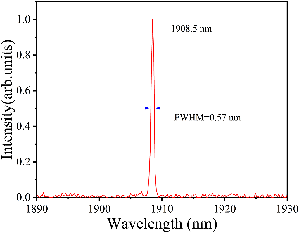
Figure 6 Spectrum of the Tm:YLF laser.
4 Conclusion
In summary, we have studied a 202 W two-crystal-in-series and dual-end-pumped Tm:YLF slab laser with a reflecting VBG as an output coupler. In order to suppress the growth of wavelength, the active heat dissipation methods were used for the VBG. The results show that the shift of wavelength was better suppressed by active heat dissipations; in particular, the effect of microchannel cooler was more prominent. When a microchannel cooler was used, the maximum CW output powers of 202 W at 1908.5 nm with linewidth (FWHM) 0.57 nm were obtained under an incident pump power of 553 W, corresponding to a slope efficiency of 39.7% and optical-to-optical conversion efficiency of 36.5%. We could also see the wavelength from 1907.5 nm at 30 W to 1908.5 nm at 202 W only shifted by 1.0 nm, which was much better than that without active cooling. The beam quality factors M 2 were 2.3 and 4.0 for horizontal and vertical directions at 202 W, respectively.
Acknowledgment
This work was supported by the National Natural Science Foundation of China (No. U20A20214).


 Open access