


Introduction
Marine ice sheets transition from grounded to floating ice at their grounding lines, a transition zone that has been of interest since theories of marine ice-sheet instability were put forward in the 1970s (Reference WeertmanWeertman, 1974; Reference Thomas and BentleyThomas and Bentley, 1978). In the Ross Sea, Antarctica, the grounding line has retreated thousands of kilometers since the end of the Last Glacial Maximum (LGM), in conjunction with significant mass loss in the interior portions of the West Antarctic ice sheet (Reference BindschadlerBindschadler, 1998; Reference Conway, Hall, Denton, Gades and WaddingtonConway and others, 1999). During its retreat, this grounding line underwent periods of stasis during which grounding-zone sediment wedges were deposited on the sea floor (Reference Mosola and AndersonMosola and and Anderson, 2006). The presence of multiple sediment wedges in the Ross Sea embayment indicates significant episodes of grounding line stability within the overall retreat since the LGM. Recent, century-scale flow variability within the grounded ice sheet has been identified using ice internal layers and surface flow features (Reference Catania, Conway, Raymond and ScambosCatania and others, 2006a; Reference Hulbe and FahnestockHulbe and Fahnestock, 2007). Our ability to project how the ice sheets will change in the future is tied to our ability to understand this past variability in ice-sheet discharge and grounding line position.
The position of the grounding line is sensitive to oceanographic conditions including sub-ice-shelf melt rates. Direct measurement of grounding-line melt rates is difficult due to limited accessibility. Conductivity–temperature–depth (CTD) measurements are often made at the ice-shelf front (e.g. Reference Jacobs, Hellmer, Doake, Jenkins and FrolichJacobs and others, 1992) while only a few measurements have been made through boreholes drilled through the ice shelf (Reference Jacobs, Gordon and ArdaiJacobs and others, 1979; Reference Nicholls, Makinson, Jacobs and WeissNicholls and Makinson, 1998). Melting can also be assessed using autonomous underwater vehicles (Reference NichollsNicholls and others, 2006) and phase-sensitive radar (Reference Corr, Jenkins, Nicholls and DoakeCorr and others, 2002; Reference Jenkins, Corr, Nicholls, Stewart and DoakeJenkins and others, 2006). Spatial patterns in sub-ice-shelf melt rates have been estimated according to flux divergence calculated using surface velocity, ice thickness and surface accumulation, assuming steady state (Reference Rignot and JacobsRignot and Jacobs, 2002; Reference Joughin and PadmanJoughin and Padman, 2003). Here too, the estimate suffers from sparse data, in this case ice thickness. Numerical models of sub-ice-shelf circulation have also been used to quantify the spatial pattern of basal melting (e.g. Reference Holland, Jacobs and JenkinsHolland and others, 2003). Reference MacAyealMacAyeal (1984) used a tidal simulation model to show that grounding-line melt occurs where the water column is reduced to <100 m, where tidal currents become strong. Overall, these models yield higher melt rates toward the grounding lines (on the order of ∼1 m a−1) for the Ross Ice Shelf (Reference MacAyealMacAyeal, 1984; Reference Assmann, Hellmer and BeckmannAssmann and others, 2003; Reference Holland, Jacobs and JenkinsHolland and others, 2003), although considerable spatial variability exists. Further, such models may lack the ability to fully resolve the changes in melt rate that occur at grounding lines where it has a sensitive dependence on the sub-iceshelf slope which undergoes large changes in shape close to the grounding line.
Here we use a remote observational technique to determine the spatial pattern of sub-ice-shelf melting at grounding lines. We use ice-penetrating radar across grounding lines near Siple Dome (SDM) and Roosevelt Island (RI) to examine the changes in layer shapes associated with the grounding line in comparison with predicted layer shapes from basal melting. This work follows on from the observations of Reference Catania, Conway, Raymond and ScambosCatania and others (2006a) who identified possible relict grounding lines in ice-sheet stratigraphy based on observations of sets of basal diffractors downstream from a syncline in the internal layers caused by basal melting. Over the syncline, layers are downwarped over a narrow (<5 km) region and become truncated at the ice–bed interface. Other hypotheses for these stratigraphic characteristics were explored by Reference Catania, Conway, Raymond and ScambosCatania and others (2006a) and include active rifting, subglacial water flow and ice-stream margin shearing; however, they concluded that the grounding-line melting hypothesis could more fully explain the observed stratigraphy. Surface lineations visible in satellite imagery that mark the locations of these relict grounding lines (and also ice-stream shear margins) (Reference Catania, Conway, Raymond and ScambosCatania and others, 2005) can be preserved in the surface topography for several hundred years (Reference NeresonNereson, 2000). We use radar profile data to locate both modern and paleo-grounding lines by identifying these distinctive stratigraphic patterns and use an isochrone model to estimate how long the grounding line has been in place at each location.
Methods
Data acquisition
We use a custom-built, low-frequency, short-pulse, ground-based radar system to image deep (>100 m) internal layers and the base of the ice sheet. We collected six radar profiles across the grounding line of SDM (Fig. 1). We call the SDM grounding line true north of the SDM summit the northern grounding line (Fig. 1b), and the SDM grounding line to the true southwest of the SDM summit the southern grounding line (Fig.1c). All SDM radar data were collected using 3 MHz antennas which provide a pulse wavelength of ∼56 m in ice and a horizontal resolution of λ/4 =14 m (Reference Welch, Pfeffer, Harper and HumphreyWelch and others, 1998). Waveforms are averaged over a horizontal spacing of ∼3 m. We also examine a previously collected radar profile across the southern boundary of RI (Fig. 1), an ice-covered island surrounded by floating ice and lying closer to the edge of the Ross Ice Shelf than SDM. The RI data were collected using coarser spacing, a lower-resolution digitizer and 7 MHz antennas. As a result, deeper layers are not as visible as in the SDM profiles. We improve the signal-to-noise ratio in all profiles by removing the mean waveform (to limit interference due to instrumentation artifacts) and by applying a bandpass filter. We convert the two-way travel time to depth assuming the wave speed in ice (168 m μs−1) and account for higher wave speeds near the surface using depth–density measurements from Reference Alley and BentleyAlley and Bentley (1988) and the Looyenga mixing equation (Reference Glen and ParenGlen and Paren, 1975) to estimate depth variation of the dielectric constant through the firn column. We also employ a higher-frequency (100 MHz) radar to image near-surface layers in some regions.

Fig. 1. (a) MODIS Mosaic of Antarctica image (T. Haran and others, http://nsidc.org/data/nsidc-0280.html) showing Siple Dome and Roosevelt Island. Radar profiles shown as white lines. Landward and seaward limits of flexure (white dots) picked from ICESat repeat-track analysis (Reference Brunt, Fricker, Padman, Scambos and O’NeelBrunt and others, 2010). (b) Detail of northern SDM radar profiles showing locations of dipping layers (black circle), point of flotation (white star), slope break (white square) and the location where basal crevasses were detected (white portion of radar line). (c) Detail of the southern SDM radar profiles. (d) Detail of RI profile.
GPS data are used to compute elevation, latitude and longitude for every radar waveform. For profiles NA–NA′ and NB–NB′ (Fig. 1), position data come from a geodetic-quality GPS receiver that provides surface elevation relative to the World Geodetic System 1984 (WGS84) ellipsoid. In this region the ellipsoid is ∼45 m above the present-day sea level and the two radar profiles are corrected to reflect the true elevation of the ice surface above mean sea level. The remaining SDM radar profiles use position data from a lower- resolution real-time kinematic GPS solution which does not require an ellipsoid correction.
The bed of the ice sheet is picked in each radar profile by finding the maximum amplitude of a radar waveform measured within a narrow time window centered on the reflected bed pulse. Ice thickness H is determined along each radar profile by subtracting the picked bed elevation from the GPS-observed surface elevation. We pick the location of the grounding line by identifying where the surface elevation is at hydrostatic equilibrium. Reference Shabtaie and BentleyShabtaie and Bentley (1982) determined a least-squares fit to 18 sets of depth–density measurements on the Ross Ice Shelf to obtain a surface elevation of h = (0.109 ± 0.005)H + 15.5 ±1.9. The grounding line is identified in each profile by a white dashed line at km 0 with error bars defined by a transparent white box (Figs 2, 3 and 5). We also indicate the landward and seaward limit of tidally forced ice flexure from a repeat-track analysis of Ice, Cloud and land Elevation Satellite (ICESat) data (Reference Fricker and PadmanFricker and Padman, 2006; Reference Brunt, Fricker, Padman, Scambos and O’NeelBrunt and others, 2010) (Fig. 1). We determine the location of the coupling line or slope break (white arrow) by identifying the location where the hydrostatic anomaly increases significantly (Reference Corr, Doake, Jenkins and VaughanCorr and others, 2001).

Fig. 2. 3 MHz radar profiles across the northern grounding line of SDM. Data in the upper ∼50 m (shown as a black band) are obscured by the direct wave from the transmitter. In all profiles, ice flows from left to right. Black arrow indicates the location of the stratigraphic syncline (described in text). The coupling line or slope break is indicated by the white arrow, and hydrostatic equilibrium is met at the grounding line which is located at km 0. Error in the grounding line position is shown as a transparent white box. (a) Profile NA–NA′. (b) Profile NB–NB′. (c) Profile NC-NC′. In (c), data extend far enough from the grounding line to cross the second hydrostatic line (Reference VaughanVaughan, 1995).


Fig. 4. 100 MHz data across the rifted terrain as indicated in Figure 3a. White lines indicate the deepest continuous layers over the near-surface crevasses in the shear margin (340 year old layer) and over the rift (440 year old layer).
Not all profiles show dipping stratigraphy associated with the grounding line. To determine where layer downwarping occurs, we differenced each picked layer from the topmost picked layer in each transect. Downwarped internal layers will show a characteristic increase in the distance from the topmost layer with depth. Using this technique, we identified those profiles that contained downwarped layers: the modern grounding lines on the north side of Siple Dome (in NA–NA′ and NB–NB′) and at Roosevelt Island (RA–RA′), and the paleo-grounding line on the south side of Siple Dome (SA–SA′, SB–SB′ and SC–SC′). The position of the dipping internal layers (if detected) is identified using stars in Figure 1 and black arrows in each radar profile (Figs 2 and 3). We also identify basal crevasses in each profile and mark this location on Figure 1 by coloring the radar profile location line white where basal crevasses are located. Most basal crevasses extend several tens of meters into the base of the ice and initiate at, or very close to, the point of flotation.
Isochrone model
The observed stratigraphic pattern at grounding lines consists of an isochrone syncline in which layers downwarp on the order of 100 m over a few kilometers, sometimes truncating at the ice–bed interface, and sets of basal diffractors that occur downstream of the syncline. Reference Catania, Conway, Raymond and ScambosCatania and others (2006a) demonstrate that basal melting is the only plausible process that can produce internal layers that downwarp with an amplitude that increases with depth and truncate at the bed.
We inspect isochrone stratigraphy from radar profiles on both sides of SDM to determine the duration and magnitude of melting resulting in the observed layers. On the north, the modern grounding line is crossed. On the south, both the modern grounding line and a paleo-grounding line (Reference Catania, Conway, Raymond and ScambosCatania and others, 2006a) are crossed. We use a kinematic model of two-dimensional ice flow perpendicular to the grounding line described by Reference Catania, Conway, Raymond and ScambosCatania and others (2006a) to investigate the shapes of internal layers across the grounding line using the typical assumption that the layers are isochrones. In our model we can vary the melt rate and duration in order to match observed layers. We only model those profiles with isochrones that show significantly dipping isochrones. We prescribe a Gaussian distribution of basal melting,
in which the peak melt rate
![]() may vary but the horizontal position where melting is maximum, x
o, is fixed. The coefficient c controls the spread of the peak in melt, and the background melt rate
may vary but the horizontal position where melting is maximum, x
o, is fixed. The coefficient c controls the spread of the peak in melt, and the background melt rate
![]() is kept at zero. We vary the spatial distribution of melt, c, for each profile to best reproduce the observed pattern of layer downwarping.
is kept at zero. We vary the spatial distribution of melt, c, for each profile to best reproduce the observed pattern of layer downwarping.
We measure model performance by calculating the ‘goodness of fit’ of modeled layers to several (eight to ten) layers picked from each radar profile following the method of Reference Nereson, Raymond, Waddington and JacobelNereson and others (1998). Each layer j is defined by a set of points i describing its shape as the set of elevations Sij
at a total number of points along a layer nj
. We compute a chi-square performance index J using the observed,
![]() , and modeled layers,
, and modeled layers,
![]() :
:
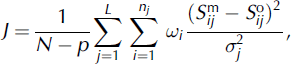
where N = ∑
j nj
is the total number of points sampled in the domain, L is the number of picked internal layers and p is the number of free parameters in the model less one. We use a weighting function ωi
to bias our analysis toward good fits in the syncline region. Models within the J < 1 contour fit the data to within expected errors. We vary the peak melt rate
![]() and the duration of melting t
m because in combination these parameters determine the total amount of bottom melting. The model-misfit analysis yields a range of melt rates and melt durations that best account for measured isochrone distortions. Where some basis exists for selecting a likely melt rate, the model may be used to estimate melt duration, which may be interpreted as the length of time the grounding line occupied a fixed position. In this way we can interpret changes in grounding line position as a result of other events that have changed ice discharge in this region in the past. We compute the model-misfit contours for J = 0.5, 1, 2, 3 and 4 but in the discussion below examine results for misfit solutions within the J < 1 contour.
and the duration of melting t
m because in combination these parameters determine the total amount of bottom melting. The model-misfit analysis yields a range of melt rates and melt durations that best account for measured isochrone distortions. Where some basis exists for selecting a likely melt rate, the model may be used to estimate melt duration, which may be interpreted as the length of time the grounding line occupied a fixed position. In this way we can interpret changes in grounding line position as a result of other events that have changed ice discharge in this region in the past. We compute the model-misfit contours for J = 0.5, 1, 2, 3 and 4 but in the discussion below examine results for misfit solutions within the J < 1 contour.
We must constrain our model results to those produced with realistic melt rates. We find that model-misfit contours do not close for peak melt rates up to ∼20 m a−1(not shown), indicating an unbounded degree of non-uniqueness for that range of melt rates. However, melt rates in this region are not expected to be this high. Reference Catania, Conway, Raymond and ScambosCatania and others (2006a) estimated that modern basal melt rates at the Kamb grounding line are on the order of ∼1 m a−1. This is similar in magnitude to other model-based sub-ice-shelf melt estimates for the Ross Ice Shelf (Reference MacAyealMacAyeal, 1984; Reference Assmann, Hellmer and BeckmannAssmann and others, 2003; Reference Holland, Jacobs and JenkinsHolland and others, 2003), so we limit our results to peak melt rates of <2 m a−1.These ocean models have a coarse resolution near the grounding line and so are not expected to capture the increases in basal melt expected near grounding lines (e.g. Reference Jenkins, Corr, Nicholls, Stewart and DoakeJenkins and others, 2006; Reference Little, Gnanadesikan and OppenheimerLittle and others, 2009). Because we set our background melt rate to zero in our misfit analysis, we predict melt rates that are likely less than expected at grounding lines. To account for this, we simply add our predicted melt rates to the suggested background melt rate from ocean models in our analysis below. Further, we expect our predicted melt rates to represent minimum grounding-line melt rates, so maximum melt durations are obtained in the model-misfit solutions when constrained by ocean model melt estimates.
Results
Radar-derived stratigraphy
Ice on the north side of SDM goes afloat in a small, slow-moving embayment bounded to the north by the southern shear margin of Bindschadler Ice Stream (Fig. 1). For all of our radar profiles here, we find the slope break just upstream of, or at the same location as, the grounding line, and our grounding-line picks fall within the zone of flexure defined by Reference Brunt, Fricker, Padman, Scambos and O’NeelBrunt and others (2010) (Fig. 1b). In profiles NA–NA′ and NB–NB′, internal layers are deformed at or just downstream from the present-day grounding line. In NB–NB′, layers downwarp up to 100 m over ∼4 km (Fig. 2). The amplitude of downwarping grows with depth, and the deepest layers are truncated at the bed or in the field of basal crevasses. Profile NC–NC′ shows no change in layer shape at, or slightly downstream of, the grounding line.
Internal stratigraphy is more complicated on the south side of SDM and reflects changes in the grounding line position over time. Downwarped internal layers (in Fig. 3) are located on grounded ice and coincide with a narrow topographic furrow visible in Moderate Resolution Imaging Spectroradiometer (MODIS) imagery (Fig. 1). Similar strati-graphic patterns are found in profiles across the furrow at ∼30 km upstream (Reference Catania, Conway, Raymond and ScambosCatania and others, 2006a). Layer downwarping is more focused at this relict grounding line than on the northern side of SDM; strong layer down-warping of ∼150 m over ∼2 km (Fig. 3b) occurs in all profiles, and layers in SB–SB′ and SC–SC′ are also down-warped up to 2 km upstream from the main layer syncline (Fig. 3b and c). This may indicate that the location where basal melt reaches its maximum rate has migrated over time or that the pattern of basal melt cannot be modeled as a simple Gaussian curve. Basal diffractors, interpreted to be basal crevasses of some (unknown) age, penetrate up to 160 m into the overlying ice and have an orientation that creates asymmetry in the hyperbolae tails (Fig. 3). This asymmetry may reflect orientation of the crevasse plane. Crevasses begin at the location of the syncline and continue across each radar profile in the direction of the modern grounding line.
Complex stratigraphy is also imaged in profile SA–SA′ (Fig. 3a). The stratigraphy from 27 to 32 km is typical of paleo-ice-stream shear margins (Reference Catania, Scambos, Conway and RaymondCatania and others, 2006b); shallowly buried crevasses overlie weak, mid-depth internal layers that are distorted in a way that is unrelated to bed topography (Fig. 3a). Crevasses here are buried at a depth similar to the burial depth in previous crossings of the same surface lineation located further upstream (Reference Catania, Scambos, Conway and RaymondCatania and others, 2006b). We trace the deepest continuous layer over these crevasses at a ∼34 m depth toward SDM (Fig. 4). Based on the interpretation by Reference Catania, Scambos, Conway and RaymondCatania and others (2006b) and Figure 3a, we conclude that this margin was last active ∼340 years ago (in AD 1669).
We identify a new type of ice terrain characterized by very large hyperbolic diffractors that penetrate the entire ice thickness between 23 and 27 km (Fig. 3a). The size of these hyperbolae suggests that the features causing diffraction are much larger than typical surface crevasses. High-frequency radar across this region (Fig. 4) shows highly deformed isochrones overlying truncated stratigraphy and evidence of wind-blown accumulation; layer packets within small depressions show typical cross-bedding structure found in aeolian depositional environments (Reference LeederLeeder, 1982). We hypothesize that this is a paleo-iceshelf rift that formed when the grounding line was upstream of its present location. Rifts are distinguished from shear margins by the fact that the hyperbolae are much larger and extend throughout the entire ice thickness, suggesting crevasses that penetrated the entire ice thickness. While active, rifts contain a floating melange of ice-shelf fragments, frozen ocean water and wind-blown snow (Reference Hulbe, Rignot and MacAyealHulbe and others, 1998; Reference Rignot and MacAyealRignot and MacAyeal, 1998). When they become inactive, rifts will fill with snow or may close, depending on ice flow. We trace the deepest continuous layer overlying the rift infill material toward SDM (Fig. 4) and assume that this layer must have formed after the rift became inactive. Using the depth and age of the layer overlying the shear margin (described above) and a depth–density relationship from Reference Smith, Lord and BentleySmith and others (2002), we determine a local accumulation rate of 0.042 m a−1, similar to the rate calculated by Reference Nereson, Raymond, Jacobel and WaddingtonNereson and others (2000) and Reference Catania, Scambos, Conway and RaymondCatania and others (2006b). This accumulation rate implies that the rift became inactive ∼440 years ago (in AD 1569).
Profiles SB–SB′ and SC–SC′ cross the modern grounding line ∼4 km downstream from the relict grounding line. The modern grounding line is not associated with any obvious distortion to internal layers, although a set of dim, relatively symmetrical basal diffractors penetrate slightly higher into the ice and overprint the first set of diffractors. We interpret these diffractors as relatively recent basal crevasses created as the grounding line migrated to its present location. The absence of overprinted basal diffractors in SA–SA′ might indicate that grounding line migration occurred more quickly through this region, perhaps suddenly.
Radar profiles were collected on RI crossing its grounding line along the western and eastern margins (Fig. 1d). MacAyeal Ice Stream runs alongside the eastern margin of RI as evidenced in surface crevasses seen in the radar profile here (Fig. 5a). Shearing here violates our model assumptions, so we only consider the radar profile across the western margin where surface crevasses occur a few kilometers downstream of the grounding line (profile RA–RA′, Fig. 5). Here we observe strongly downwarped layers that indicate a larger volume of ice lost to basal melt than the other profiles (internal layers downwarp up to ∼300 m over just a few kilometers). No basal crevasses are observed at the grounding line crossing, although faint near-bed disturbances observed beyond km2 (Fig. 5) may indicate their presence just off the profile. Our grounding-line pick agrees reasonably well with the inward point of flexure from ICESat repeat-track analysis (Fig. 1d).

Fig. 5. (a) 7 MHz radar profile across the eastern margin of RI. The modern grounding line is located at km 0. The slope break is identified with a white arrow. (b) Western margin of RI also shows the location of downwarped layers indicated by black arrow. (c) Model misfit for internal layers in (a). Contours represent solutions for J = 0.5, 1, 2, 3 and 4. Dashed line at 0.02 m a−1 represents predicted melt rate by Reference Holland, Jacobs and JenkinsHolland and others (2003).
Ages of grounding lines
The crossings NA–NA′ and NB–NB′ on the north side of SDM are in close proximity, so we consider the model-misfit results of these two profiles together (Fig. 6). No change in isochrone shape was detected for NC–NC′. Larger dips in the isochrones along NB–NB′ indicate either a higher melt rate or longer melt duration than at NA–NA′ (Fig. 6). However, we constrain the melt duration and melt rates in this region to be consistent across both profiles and so only consider melt durations and melt rates from the model-misfit curves where they overlap for both NA–NA′ and NB–NB′ (Fig. 6). We obtain a minimum melt rate of ∼0 m a−1 from our misfit solutions, which when combined with an estimated ocean-model melt rate of 0.2 m a−1(Reference Holland, Jacobs and JenkinsHolland and others, 2003) gives a maximum melt duration common to NA–NA′ and NB–NB′ of 200–400 years (that is, since ∼AD 1609–1809) according to the J = 1 misfit solution (Fig. 6).

Fig. 6. Model misfit for dipping internal layers across the north SDM grounding line. Contours represent solutions for J = 0.5, 1, 2, 3 and 4. Results for (a) profile NA–NA′ and (b) profile NB–NB′. Dashed line at 0.2 m a−1 represents predicted melt rate by Reference Holland, Jacobs and JenkinsHolland and others (2003).
On the south side of SDM we compute the model misfit for the paleo-grounding-line feature identified in each profile because the modern grounding line shows no change in isochrone shape (Fig. 7). Multiple crossings of the paleo-grounding line (using both the data presented here and from Reference Catania, Conway, Raymond and ScambosCatania and others (2006a)) allow us to constrain our model results again assuming uniform changes in grounding line characteristics between these radar crossings. As a result, we search for melt durations and melt rates from each misfit solution that overlap. Our misfit solutions give a common minimum melt rate of 0.18 m a−1 which is combined with a predicted ocean-model melt rate of 0.02 m a−1 (Reference Holland, Jacobs and JenkinsHolland and others, 2003) to obtain a minimum melt rate of 0.2 m a−1. This assumes that the melt rate here has not changed since the migration of the grounding line. This melt rate gives solutions over a limited melt duration indicating that the grounding line has been in this paleo-location for at most ∼400–500 years. When combined with our age constraint on the rift, we determine that the Kamb Ice Stream paleo-grounding line was in place 840–940 years ago (AD 1069–1169).

Fig. 7. Model misfit for dipping internal layers across the paleo-grounding line at the south SDM boundary. Contours represent solutions for J = 0.5, 1, 2, 3 and 4. Results for (a) profile SA–SA′, (b) profile SB–SB′ and (c) profile SC–SC′. Dashed line at 0.02 m a−1 represents predicted melt rate by Reference Holland, Jacobs and JenkinsHolland and others (2003).
The minimum melt rate allowed by the RI model is 0.3 m a−1 (Fig. 5c). The predicted melt rate from ocean models for this region is 0.02 m a−1 (Reference MacAyealMacAyeal, 1984; Reference Holland, Jacobs and JenkinsHolland and others, 2003), giving an estimated melt rate of 0.32 m a−1. This value is higher than at SDM and gives a maximum melt duration of ∼400 years, implying that the grounding line has been in this location since ∼AD 1609, but possibly later.
Discussion
Stratigraphy associated with both modern and paleo-grounding lines is characterized by basal crevasses and sometimes downwarped internal layers beginning at, or slightly downstream of, the point of flotation (Figs 2 and 3). The localized nature of the stratigraphic downwarp indicates that sub-ice-shelf melting in these locations is not constant in time. If melting were constant over time at a fixed location, layers would downwarp at the grounding line and advection would propagate that signal downstream. Further, our observations suggest that melt rates can be non-uniform over just tens of kilometers as observed by the lack of a melt signature along NC–NC′. We find that melt-related stratigraphy is preserved at grounding lines where ice flow is slow or melt rates are relatively large, and where the grounding line has been fixed for at least a few hundred years.
Model simulations of the amount of basal melting beneath the Ross Ice Shelf (Reference MacAyealMacAyeal, 1984; Reference Holland, Jacobs and JenkinsHolland and others, 2003; Reference Dinniman, Klinck and SmithDinniman and others, 2007) generally produce high melt rates around the northeastern coast of SDM and low melt rates along the southern coast of SDM and around RI. Our analyses are consistent with those expectations for the modern SDM coastline; the modern grounding line along the northern edge of SDM experiences enough basal melting to cause localized layer downwarping. Further, we see no evidence of basal melting in the radar profiles across the modern grounding line along the southern edge of SDM. For RI, we conclude that melt rates are an order of magnitude (or more) higher than predicted from ocean cavity circulation models.
Differences between melt rates predicted by ocean circulation models and our ice flowline models are likely due to the inability of the ocean models to resolve subtle features in the geometry of the sub-ice-shelf cavity at the grounding line. As a result, these models likely under-predict melt rates at the inland grounding line. Despite this, these models provide background melt rates for grounding lines that can be used in combination with our model-misfit results to predict a lower bound on the melt rate at the grounding line and thus maximum melt durations for the grounding lines examined here. Using our isochrone model, we find evidence for grounding line advance on Kamb Ice Stream from its inland location (seen in SA, SB and SC) in ∼AD 1069 to its present location in ∼AD 1569. The modern Kamb grounding line, where crossed, shows few signs of basal melting, indicating that it may have shifted frequently since ∼AD 1569. The grounding line on the north side of SDM has been in place for, at most, the last 200–400 years. Here, melting is spatially variable since NC–NC′ does not show signs of basal melting (Fig. 2c). The grounding line at RI is more difficult to understand since melt rates are not well constrained here. We observe the largest total melt amount here (the product of melt duration and melt rate) and the most downwarping in isochrones. Using a minimum estimated melt rate of 0.32 m a−1, the RI grounding line (along the southwestern edge) has been in place for at most ∼400 years, similar to that on the northern side of SDM.
The geometry of the sub-ice-shelf cavity is important to the spatial pattern of melting and freezing at the base of the ice shelf (Reference SchoofSchoof, 2007; Reference Walker, Dupont, Parizek and AlleyWalker and others, 2008; Reference Little, Gnanadesikan and OppenheimerLittle and others, 2009). Steep slopes encourage melting because they drive high melt-plume velocities and high rates of entrainment, and lead to a positive feedback in which increases in sub-ice-shelf melt increase the slope, which further focuses and increases melt (Reference Payne, Holland, Shepherd, Rutt, Jenkins and JoughinPayne and others, 2007). To consider the effect of the geometry of the ice-shelf cavity on melt rates, we calculate the change in surface slope at the slope break with the assumption that the change in surface slope reflects the basal slope as ice goes afloat (Table 1). We compare this to the amount of melt (the product of the minimum melt rate and melt duration predicted by the model-misfit J = 0.5 solutions) for modern grounding line crossings only. For those radar profiles with no change in stratigraphy at the grounding line, we assume that the melt rate is zero and so the amount of melt is also zero.
Table 1. Minimum modelled melt rates for the J = 0.5 model-misfit solution added to the predicted ocean-model melt rate for each radar profile (where no isochrone syncline exists,
![]() is assumed to equal 0), melt duration at
is assumed to equal 0), melt duration at
![]() , melt amount, mean slope calculated before and after the slope break and the calculated change in slope
, melt amount, mean slope calculated before and after the slope break and the calculated change in slope

The magnitude of the surface slope at the grounding line varies with our estimated melt amount in all sampled locations. At our RI transect, we find the greatest change in slope across the grounding line and, correspondingly, the greatest amount of melt (Table 1). NB–NB′ has a moderate change in slope at the grounding line and a moderate melt amount, while NA–NA′ has the smallest change in slope and the smallest melt amount. The lack of melting at SC–SC′ may be due to the relatively small change in slope at the grounding line here (Table 1). For the remaining profiles (NC–NC′ and SB–SB′), we observe no detectable change in layer shape across the modern grounding lines despite moderate slope changes. For SB–SB′, the lack of any melt pattern may be due to frequent shifts in the position of this grounding line over time, an explanation that would also account for the multiple, overprinted sets of basal crevasses found through this region. In addition, the landward limit of tidal flexure from Reference Brunt, Fricker, Padman, Scambos and O’NeelBrunt and others (2010) (plotted in Fig. 1) occurs closer to the southern end of the SB–SB′ and SC–SC′ profiles (Fig.1c), ∼10 km downstream from our grounding line picks. This might indicate that this region is loosely grounded, or perhaps an ice plain. While we have sampled only a few locations, our analysis supports the idea that surface-slope changes at the grounding line can serve as a proxy for subice-shelf melt there. This is a more easily attainable measurement than the shape of the sub-ice-shelf cavity.
Conclusions
Distortions to ice-sheet stratigraphy are used here to infer basal melt rates and past events on grounding lines at several locations along the Ross Ice Shelf. These observations are important both for establishing a chronology of past ice-sheet variability and for understanding processes at the grounding line. We find unexpectedly large melt rates in some locations, and our (limited) sample suggests considerable spatial variations in basal melt rates, driven in part by the sub-ice-shelf slope at the grounding line. In model experiments, Reference Walker, Dupont, Parizek and AlleyWalker and others (2008) found that while the average basal melt rate exerted the greatest influence over the rate of grounding line retreat, the spatial pattern of basal melting across the grounding line was also very important: grounding line retreat accelerates as melting becomes more focused at the grounding line. Our observations support a grounding line melt pattern that is much more focused than previous estimates for the Ross and other ice shelves (Reference Holland, Jacobs and JenkinsHolland and others, 2003; Reference Joughin and PadmanJoughin and Padman, 2003). In part, this is because of the increased resolving power of our radar profiles compared to these model domains. We observe the highest melt rates within 1–2 km of the grounding line, and negligible melt rates just a few kilometers downstream of the grounding line.
We deduce temporal variability from the melt-related stratigraphy on the south side of SDM where both modern and relict grounding line positions are detected; the relict grounding line shows greater losses of ice from basal melting than occur at present. Our model-misfit solutions indicate that the observed melting at this paleo-grounding line cannot be explained using modern melt rate estimates from ocean circulation models. Either the models significantly underestimate melt rate in some locations or the melt rate has decreased significantly since grounding line readvance ∼440 years BP. The pattern of crevasse overprinting here suggests that the grounding line may not hold a fixed position in this region, which might explain the lack of any observable melt signature in the stratigraphy at the modern grounding line.
Grounding-line retreat and readvance on the south side of SDM coincides with the stagnation (850 years BP) and reactivation (450 years BP) respectively of neighboring Whillans Ice Stream (Reference Hulbe and FahnestockHulbe and Fahnestock, 2007). The grounding lines on the north side of SDM and RI have been in their current position since ∼400 years BP. This roughly coincides with the shutdown of ‘Siple Ice Stream’, a distributary of Kamb Ice Stream (personal communication from B. Smith, 2002) which flowed along the northern flank of SDM. Our observations support the hypothesis that variations in ice-stream discharge are associated with significant variations in grounding line position (Reference Hulbe and FahnestockHulbe and Fahnestock, 2007).
Acknowledgements
This work was supported by US National Science Foundation (NSF) grant OPP-0538120 to Catania and Hulbe. We thank H. Corr of the British Antarctic Survey and P. Gogineni of the Center for Remote Sensing of Ice Sheets (CReSIS), University of Kansas, for the loan of critical radar equipment, and H. Henry, J. Greenbaum, A. Mironov, A. Lamb, K. Cruikshank and Raytheon Polar Services support staff for valuable assistance in the field. We also thank R.C.A. Hindmarsh and G. Leysinger Vieli for thorough reviews that greatly improved the quality of the manuscript.


