


Introduction
Satellite communications play a key role in 5 G and Beyond-5 G networks, providing connectivity in rural or isolated areas, for mobility applications (aero/maritime scenarios), and as a backhaul network of the terrestrial communications [Reference Liolis, Geurtz, Sperber, Schulz, Watts, Poziopoulou, Evans, Wang, Vidal, Tiomela Jou, Fitch, Diaz Sendra, Sayyad Khodashenas and Chuberre1–Reference Elbert3]. Currently, the broadband communications via satellite are mainly provided by geostationary satellites operating in Ka-band, known as high throughput satellites (HTS) [Reference Elbert3–Reference Fenech, Amos, Tomatis and Soumpholphakdy5]. HTS systems split the service area into a hundred of small cells, which makes it possible to implement frequency and polarization reuse schemes that improve the efficiency of the available spectrum and reduce the interference between adjacent service cells [Reference Fenech, Amos, Tomatis and Soumpholphakdy5, Reference Martinez-de-Rioja, Martinez-de-Rioja, Rodriguez-Vaqueiro, Encinar, Pino, Arias and Toso6]. Therefore, the antenna farm on board HTS must generate a cellular coverage formed by more than 100 high-gain beams in a four-color reuse scheme, simultaneously at transmit (Tx) and receive (Rx) frequencies in Ka-band. The four-color scheme is reached by using two orthogonal circular polarizations (CP) and by splitting the Tx and Rx links into two sub-bands. The most widely used antenna farm on board HTS is based on four reflector antennas, with a single offset configuration and a one-feed-per-beam architecture [Reference Rao7, Reference Rao, Tang and Hsu8]. Reflector antennas cannot generate adjacent beams with the required angular separation between them (around 0.5°), since the feed chains would be physically overlapped. Thus, four reflector antennas are commonly embarked on the satellite, where each reflector generates all the beams in a single color of the reuse scheme (adjacent beams are never generated in the same color).
The limitation of reflector antennas to provide so closely spaced beams can be overcome by using reflectarray antennas. The independent operation at different frequencies [Reference Martinez-de-Rioja, Martinez-de-Rioja and Encinar9–Reference Smith, Gothelf, Kim and Breinbjerg11] or polarizations [Reference Zhou and Sørensen12–Reference Mener, Gillard, Sauleau, Bellion and Potier14] provided by reflectarrays can be used to generate two slightly overlapping beams per feed. A dual band reflectarray antenna with independent operation in orthogonal CPs would allow to reduce the number of antennas on board the HTS to generate the four-color cellular coverage, from the four conventional reflectors to two reflectarrays [Reference Naseri, Riel, Demers and Hum15, Reference Martinez-de-Rioja, Martinez-de-Rioja, Encinar, Pino, Gonzalez-Valdes, Rodriguez-Vaqueiro, Arias and Toso16]. The dual band operation in the reflectarray can be defined to generate adjacent beams at each sub-band for the Tx link (or the Rx link). However, the independent operation at close frequencies makes the antenna performance unstable in band, requiring heavy optimizations of the printed elements on the reflectarray surface [Reference Martinez-de-Rioja, Martinez-de-Rioja, Encinar, Rodriguez-Vaqueiro and Pino17].
In this paper, a parabolic reflectarray is proposed to generate half the required cellular coverage in HTS simultaneously at Tx and Rx frequencies in Ka-band. The reflectarray has been defined with a diameter of 1.8 m to provide two orthogonal CP beams per feed, with an angular separation of 0.56°. Moreover, the beams in Rx are generated in the orthogonal CP than in Tx, as required in satellite applications. The operating principle of the reflectarray is described, as well as a novel design approach for large reflectarray antennas that makes it possible to promptly obtain a layout of every printed element on the antenna, with an extremely low computational cost. This initial layout can be used as a starting point for a further optimization of each reflectarray cell, reducing the computation time. The 1.8 m reflectarray has been designed and simulated considering a cluster of 27 dual band dual-CP feed-horns to produce a cellular coverage of 54 spot beams in two different colors (two orthogonal CPs) simultaneously at 19.7 and 29.5 GHz. A second reflectarray operating at slightly different operating frequencies would generate the second half of the final coverage, formed by 108 beams in a four-color reuse scheme at Tx and Rx frequencies in Ka-band. Note that the number of feed chains on board the satellite would be also reduced by half, from 108 feeds to 54, since each feed generates two spaced beams. The design and simulation tools have been experimentally validated by the manufacturing and testing of a parabolic reflectarray scaled by 0.5, with a diameter of 0.9 m [Reference Martinez-de-Rioja, Martinez-de-Rioja, Rodriguez-Vaqueiro, Encinar, Pino, Arias and Toso6].
Operating principle
The proposed reflectarray operates by the variable rotation technique (VRT) applied to the elements printed on the antenna surface, which is illuminated by electromagnetic waves in dual-CP [Reference Smith, Gothelf, Kim and Breinbjerg11]. According to the VRT, a reflectarray element rotated αrot in a periodic environment introduces a phase shift in the reflected CP field equal to 2⋅αrot, with opposite sign for each orthogonal CP. Figure 1 shows a reflectarray cell with a rotated patch, including the regular and rotated coordinate systems, associated to the vectors $( \hat{x}, \;\hat{y})$ and $( \hat{x}^{\rm ^{\prime}}, \;\hat{y}^{\rm ^{\prime}}$
 , respectively.

Fig. 1. Reflectarray cell based on a rectangular patch with a rotation angle αrot = 30°.
The VRT can be used to split in opposite directions the orthogonal CP beams reflected by a reflectarray antenna, when it is illuminated by a dual-CP feed horn, as in [Reference Somolinos, Florencio, González, Encinar and Cátedra18]. In [Reference Zhou and Sørensen12], a parabolic reflectarray was proposed to split in opposite directions the orthogonal CP beams by VRT, using the parabolic surface of the reflectarray to focus high-gain beams. In this work, a 1.8 m parabolic reflectarray has been designed based on the same operating principle, but with an independent application of the VRT at 19.7 and 29.5 GHz, thus providing two spaced orthogonal CP beams per feed at Tx and Rx frequencies in Ka-band. Figure 2 shows a schematic representation of the reflectarray antenna, whose parabolic configuration is given by a projected diameter, D, equal to 1.81 m, a clearance, C, of 0.35 m, and a focal distance, f, of 2.72 m. The antenna configuration has been defined to satisfy the requirements in gain and beamwidth typically specified in HTS [Reference Martinez-de-Rioja, Martinez-de-Rioja, Encinar, Rodriguez-Vaqueiro and Pino17].
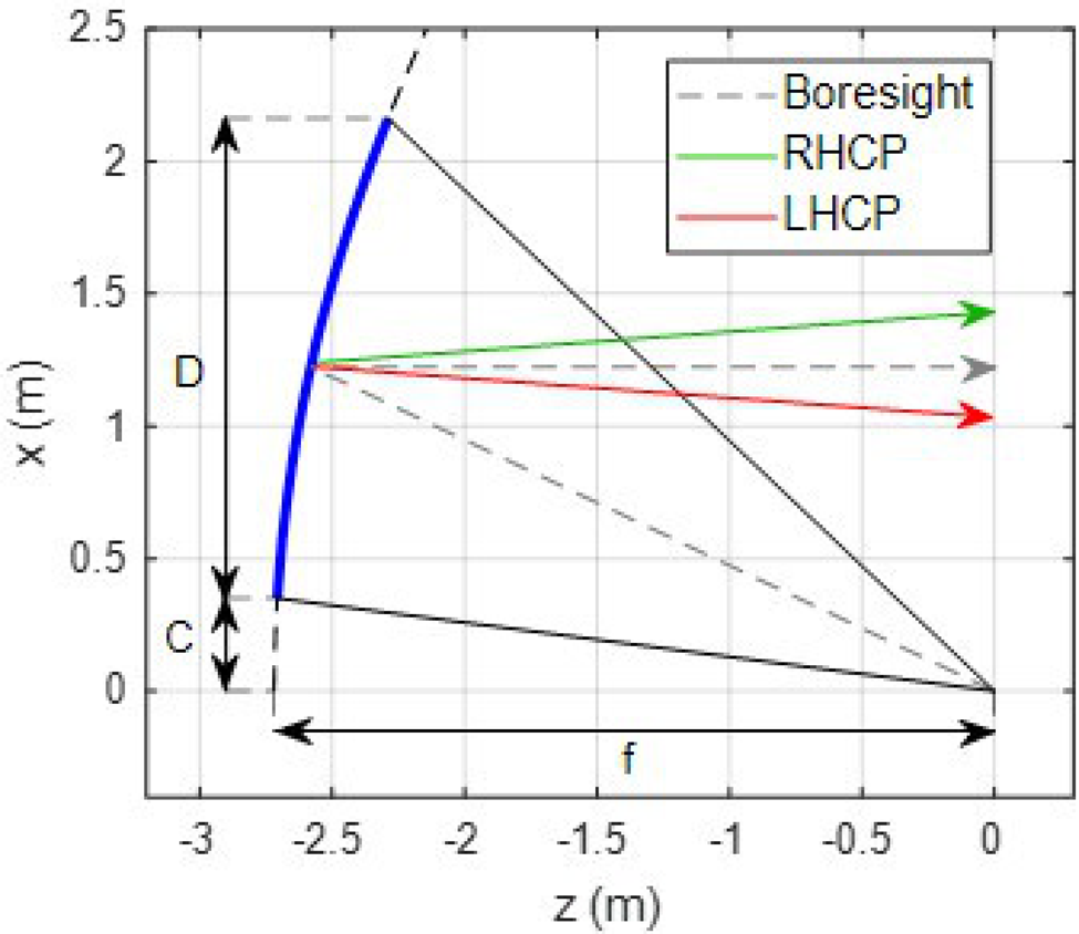
Fig. 2. Parabolic reflectarray antenna with the boresight and scanned directions of radiation.
The VRT also requires a careful adjustment of the dimensions of the rotated elements to minimize the cross-polar component in the reflected field. In order to cancel the cross-polar component in CP, the elements must be adjusted to provide a difference of 180° between the phases of the co-polar reflection coefficients referred to the linear components of the incident field in the rotated coordinate system of each cell, defined as $R_{XX}^{\rm ^{\prime}}$ and $R_{YY}^{\rm ^{\prime}}$
 in (1), where the linear components of the tangential incident and reflected fields associated to the rotated coordinate system on each cell are $E{\rm ^{\prime}}_{x, \;y}^{\;inc}$
 and $E{\rm ^{\prime}}_{x, y}^{\;ref}$
 . For instance, the phases of $R_{XX}^{\rm ^{\prime}}$
 and $R_{YY}^{\rm ^{\prime}}$
 in the cell shown in Fig. 1 would be independently controlled by the dimensions lx and ly of the patch, which should be sized to provide the required 180° phase difference.

The independent implementation of the VRT at two different frequencies requires a reflectarray cell with two types of printed elements, one for each frequency band. The elements will be independently rotated, so the cell should be designed to provide the 180° phase difference between the phases of $R_{XX}^{\rm ^{\prime}}$ and $R_{YY}^{\rm ^{\prime}}$
 simultaneously at both operating frequencies (19.7 and 29.5 GHz).
Reflectarray cell
The reflectarray cell has a dual-layer configuration that includes two types of printed elements: two symmetrical circular arcs and two orthogonal sets of three parallel dipoles, as shown in Fig. 3. The choice of these elements is based on the fact that they can be independently rotated without colliding with each other. The arcs are used to control the phase-shift at 19.7 GHz, while the stacked sets of dipoles ensure the required phases at 29.5 GHz. The size of the cell is 6.5 mm × 6.5 mm, which is 0.64 λ at 29.5 GHz. The width of the arcs is 0.2 mm, with an inner radius of 2.65 mm. The dipoles have been defined with a width of 0.4 mm, a separation of 1.2 mm between adjacent dipoles from center to center, and with a fixed scale factor of 0.67 between the lengths of the central and lateral dipoles of each set of three parallel dipoles (lA 2 = 0.67⋅lA 1, lB 2 = 0.67⋅lB 1 in Fig. 3). In order to provide the 180° phase difference between the phases of $R_{XX}^{\rm ^{\prime}}$ and $R_{YY}^{\rm ^{\prime}}$
 at 19.7 GHz, the length of the rotated arcs (given by Ω in Fig. 3) must be adjusted, cell by cell. In the same way, the lengths of the upper and lower dipoles can be independently adjusted to control the phases of $R_{XX}^{\rm ^{\prime}}$
 and $R_{YY}^{\rm ^{\prime}}$
 at 29.5 GHz. Note that the degrees of freedom provided by the dipoles could be used to split the orthogonal CP beams while focusing high-gain beams from a flat reflectarray antenna, as in [Reference Florencio, Encinar, Boix, Barba and Toso19].

Fig. 3. Proposed reflectarray cell. (a) Top view, (b) lateral view.
Although the thermomechanical design of the antenna goes beyond the scope of the work, the dielectric substrates of the reflectarray have been chosen taking into account that the antenna is proposed for space applications. The lower substrate has been defined as 1 mm Quartz-fiber Qzll/EX-1516 (ɛr = 3.2, tanδ = 0.004), which is a prepreg fabric with quartz fibers and low loss resin, characterized by its mechanical strength and dimensional stability. For the upper substrate, a thin substrate of 50 μm Rogers R/Flex 3000 (ɛr = 2.9, tanδ = 0.0025) has been considered, which is similar to the Kapton polyimide used in aerospace applications. The proposed 1.8 m parabolic reflectarray is made up of 62 654 reflectarray cells.
The electromagnetic analysis of the reflectarray cell has been performed by an in-house software tool based on the Method of Moments in the Spectral Domain (MoM-SD) considering a periodic environment [Reference Florencio, Boix and Encinar20]. This tool makes it possible an efficient analysis of the cell under any angle of incidence. The phase shift introduced by the reflectarray cell has been analyzed when both arcs and dipoles are independently rotated. Figures 4 and 5 show the phase introduced in RHCP and LHCP at 19.7 and 29.5 GHz respectively, when the arcs and dipoles are independently rotated. The arcs have been defined with a length of 4.2 mm (Ω = 88°), and dipoles with lA 1 = 2.3 mm and lB 1 = 2.2 mm. As can be seen, the phases at 19.7 GHz are barely affected by the dipoles, which proves the independent operation of the arcs at 19.7 GHz.

Fig. 4. Phase (°) in (a) RHCP and (b) LHCP introduced at 19.7 GHz when the arcs and dipoles are independently rotated.

Fig. 5. Phase (°) in (a) RHCP and (b) LHCP introduced at 29.5 GHz when the arcs and dipoles are independently rotated.
Design process
The 1.8 m reflectarray is expected to deviate ±0.28° the orthogonal CP beams focused by the parabolic surface of the reflectarray antenna. The objective phase distributions on the antenna surface at 19.7 GHz to split ±0.28° the orthogonal CP beams in the xz-plane are shown in Fig. 6. Note that opposite phases are required in RHCP and LHCP to deviate in opposite directions the orthogonal CP beams, thus these distributions can be fully implemented by the VRT applied to the arcs. The phase distributions at 29.5 GHz to also deviate ± 0.28° the orthogonal CP beams are shown in Fig. 7, which would be provided by the rotation of the dipoles. The phase distributions have been defined in order to generate orthogonal CP beams at 19.7 and 29.5 GHz, so the phases in RHCP depicted in Figs 6 (a) and 7(a) show an opposite phase variation (as the phases in LHCP in Figs 6(b) and 7(b)).

Fig. 6. Required phase distribution (°) at 19.7 GHz. (a) RHCP, (b) LHCP.

Fig. 7. Required phase distribution (°) at 29.5 GHz. (a) RHCP, (b) LHCP.
The rotation angle of every element on the reflectarray antenna can be computed dividing by two the required phase-shifts in RHCP, at 19.7 GHz for the rotation angles of the arcs (αArc) and at 29.5 GHz for the rotation angles of the dipoles (αDip). The distribution of rotation angles for the arcs and dipoles on the reflectarray surface is shown in Fig. 8. Note that the arcs and dipoles are rotated in opposite senses to generate orthogonal CP beams at 19.7 and 29.5 GHz.

Fig. 8. Rotation angles (°) of (a) the arcs and (b) the dipoles.
Then, the lengths of the rotated arcs and dipoles must be adjusted cell by cell to provide a difference of 180° between the phases of R’XX and R’YY at 19.7 and 29.5 GHz, considering the real angles of incidence on each cell. Figures 4 and 5 have shown that the impact of the dipoles at 19.7 GHz is smaller than the effect of the arcs at 29.5 GHz, so the sizing process of the elements starts by adjusting the lengths of the rotated arcsat 19.7 GHz, and then the lengths of the rotated dipoles at 29.5 GHz, taking into account the designed lengths of the arcs. The sizing process is based on a dimensional sweep prior to an optimization routine, which provides a fast convergence only when the solution is close enough. A block diagram with the design process applied to each reflectarray cell is shown in Fig. 9.

Fig. 9. Scheme of the cell design process.
Implementing this cell-by-cell design process for large antennas may require an excessive amount of time (the proposed antenna has 62 654 reflectarray cells). Note also that the computational time can be increased due to the independent sizing of the arcs and then the dipoles, which may require an iterative process to reduce the effect of the last adjustment of the dipoles on the Tx performance. However, the high degree of accuracy required in antennas for space applications penalizes the use of design methods with more basic approximations, like those based on lookup tables. The computational time can be strongly reduced by selecting starting dimensions for the lengths of all the elements close to those that will be finally reached after the design process, which requires a customized starting point for every cell. An appropriate starting point removes the need to implement the dimensional sweep prior to the optimization routine for the adjustment process of every element. The difference between starting with a dimensional sweep or directly with the optimization routine may reduce the computational time by a magnitude depending on the number of steps in the dimensional sweep. The need to implement iterative steps for the adjustment of arcs and dipoles can also be removed by an appropriate initial sizing of the elements, since the arcs would be adjusted considering initially sized dipoles with dimensions close to those of the finally designed dipoles.
A novel method has been developed to obtain this initial layout, based on the initial adjustment of the elements placed in the central lines of the antenna. Thus, from the 62 654 reflectarray cells arranged in a grid of 286 × 279 cells, only 286 + 279–1 = 564 cells must be designed (considering a conventional non-optimal starting sizing of the elements), 111 times fewer cells than for the complete reflectarray antenna. Then, a weighted replication process is used to obtain the dimensions of all the rotated elements on the antenna surface. This process firstly replicates the sizing of the elements designed in one of the central lines of the antenna, and then introduces a correction given by the difference between the dimensions of the designed elements in the orthogonal central line of the antenna. For instance, the length lA 1 for a cell placed in coordinates (xi, yi) with respect to the center of the antenna (considering a flat grid of cells) would be obtained as shown in (2), from the designed lengths lA 1 in the cells placed in the central lines of the antenna. This replication process has made it possible to maintain the accurate cell-by-cell design process, considering the real angles of incidence in the 62 654 reflectarray cells.

Simulated results
The designed parabolic reflectarray has been analyzed by an in-house software that combines physical optics [Reference Rahmat-Samii21] with the aforementioned MoM-SD code to characterize the surface reflection on the reflectarray antenna. The simulations have considered that the parabolic reflectarray is illuminated by 27 dual-CP feeds to generate 54 spot-beams in two orthogonal CPs (two different colors). Figure 10 shows the group of feeds and the spot distribution associated to the feed array. Note that a second parabolic reflectarray operating at slightly different frequencies would produce a similar coverage of 54 spots, and the overlapped coverage of both reflectarrays would produce 108 spots in a four-color reuse scheme. The feed-horn reported in [Reference Schneider, Hartwanger and Wolf22] has been taken as a reference to define the characteristics of the feeds: the aperture diameter of the horns is 54 mm, so the distance between adjacent feeds has been set to 55 mm, and the radiation of the feeds has been modelled by a cosq(θ) distribution with q = 24 at 19.7 GHz and q = 42 at 29.5 GHz. Note that the simulation tool for the reflectarray antenna is suitable to include the incident field on the reflectarray antenna computed by a more realistic model of the feed (as spherical-mode expansion), or even from feed measurements; however, at this point, the cosq(θ) function is considered a sufficiently suitable approach.
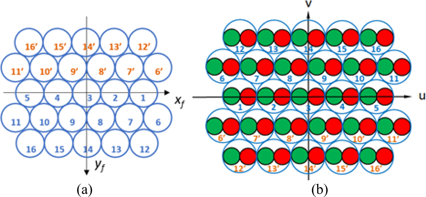
Fig. 10. Distribution of (a) the 27 feed-horns and (b) the 54 spots associated to the feeds.
Since the antenna configuration is symmetric with respect to the xz-plane, the simulations have considered only the feeds numbered from 1 to 16 in Fig. 10(a). Therefore, the 32 spot-beams generated by the selected 16 feeds have been computed at 19.7 and 29.5 GHz. Figure 11 shows the contour patterns at 46 and 45 dBi for the beams at 19.7 and 29.5 GHz, respectively. The contours show an angular diameter of 0.65° and a separation between adjacent beams of 0.56° from center to center. Moreover, it can be seen that the beams are generated in orthogonal CPs at 19.7 and 29.5 GHz, due to the opposite sense of rotation of the arcs and dipoles (see Fig. 8).
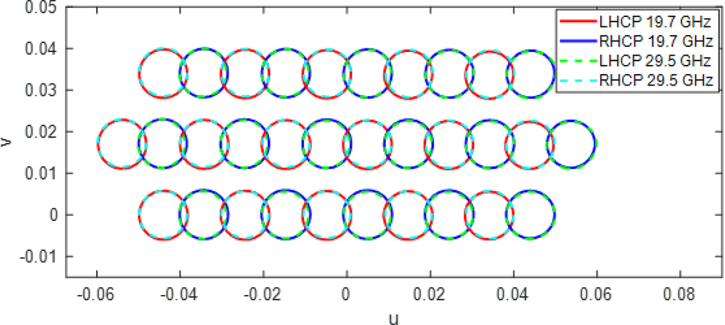
Fig. 11. Contour patterns of the 32 beams generated by 16 dual-CP feeds.
The simulated radiation patterns have also been analyzed in the main planes of the triangular spot distribution. Figure 12 shows the elevation cut of the radiation patterns at 19.7 GHz in RHCP for the beams generated by feeds #1 to #5, while the cut of the radiation patterns at 19.7 GHz in LHCP for the beams generated by feeds #12 to #16 is shown in Fig. 13. The figures include masks to show the zone of coverage of every beam, with a gain level of 46 dBi and a beamwidth of 0.65°, and the zone of the adjacent beams with a gain level of 26 dBi. The simulated radiation patterns do not show differences between the beams in RHCP and LHCP. The maximum gain of the beams at 19.7 GHz is around 50 dBi, providing a radiation efficiency close to 70% (the cosq(θ) distribution of the feeds at 19.7 GHz provides an edge illumination on the reflectarray of −12 dB). The radiation patterns at 19.7 GHz also show a side-lobe level slightly lower than 20 dB below the end-of-coverage (EOC) level of 46 dBi, and a cross-polar discrimination below the level of 26 dBi of the masks.
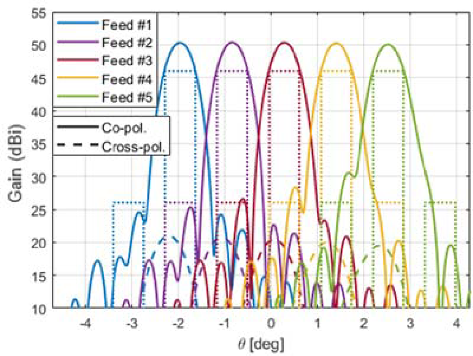
Fig. 12. Simulated radiation patterns in RHCP at 19.7 GHz in the plane v = 0 (generated by feeds 1–5).

Fig. 13. Simulated radiation patterns in RHCP at 19.7 GHz in the plane v = 0.034 (generated by feeds 12–16).
Figures 14 and 15 show the same cuts depicted in Figs 12 and 13 for the radiation patterns at 29.5 GHz. Due to the larger electrical size of the reflectarray at 29.5 than at 19.7 GHz, the maximum gain of the beams at 29.5 GHz is close to 53 dBi, associated to a radiation efficiency of around 65%. The radiation patterns at 29.5 GHz also show larger levels of SLL than at 19.7 GHz, as a result of the lower edge illumination provided by the feeds at 29.5 GHz (around −20 dB), and cross-polar levels 20 dB below the EOC gain.
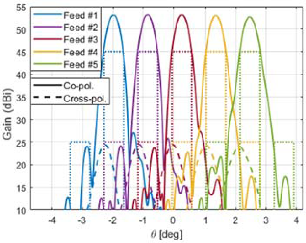
Fig. 14. Simulated radiation patterns in LHCP at 29.5 GHz in the plane v = 0 (generated by feeds 1–5).

Fig. 15. Simulated radiation patterns in LHCP at 29.5 GHz in the plane v = 0.034 (generated by feeds 12–16).
Experimental validation
The design and simulation software tools described in this paper have been experimentally validated by a parabolic reflectarray scaled in a factor of 0.5, which has been manufactured and tested. The 0.9 m parabolic reflectarray has been designed to deviate ±0.59° the orthogonal CP beams by using the VRT, simultaneously at Tx and Rx frequencies in Ka-band. The manufactured antenna, which is shown in Fig. 16, has 15 748 reflectarray cells.
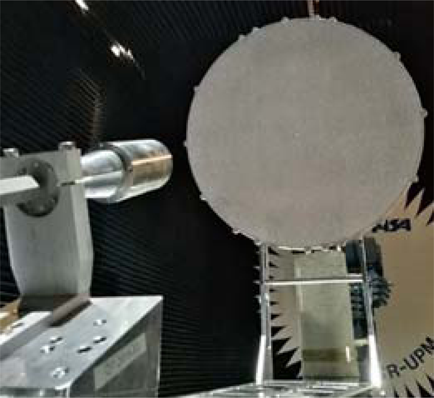
Fig. 16. Manufactured parabolic reflectarray scaled in a factor of 0.5.
The measurements have proven that the parabolic reflectarray, illuminated by three dual-CP feeds, generates six beams in two orthogonal CPs, with also orthogonal CP beams at Tx and Rx frequencies. Figure 17 shows the measured contour patterns of the six beams at 40.6 dBi, and Figure 18 shows the measured radiation patterns of the parabolic reflectarray when it is illuminated by a single dual-CP feed. The measurements of the prototype have been reported in [Reference Martinez-de-Rioja, Martinez-de-Rioja, Rodriguez-Vaqueiro, Encinar, Pino, Arias and Toso6].

Fig. 17. Measured contour patterns at 40.6 dBi of the six beams generated by three feeds.
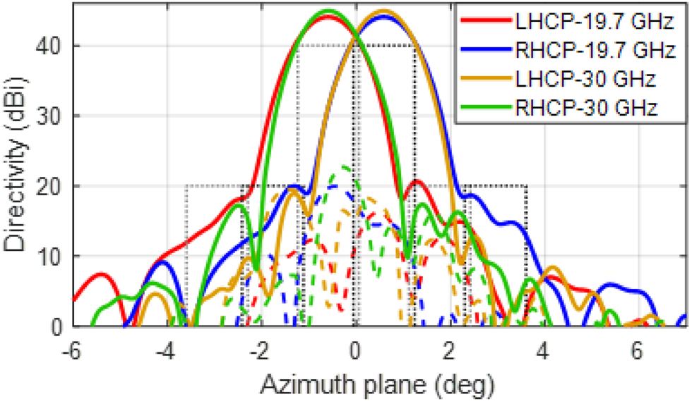
Fig. 18. Cut of the measured radiation patterns for the beams generated by one feed.
The comparison between the measured and simulated radiation patterns is depicted in Fig. 19 for the beam generated at 19.7 and 29.5 GHz in RHCP by one of the feeds. The comparison shows an excellent agreement between measurements and simulations at both frequencies, particularly for the co-polar components. The successful operation of the fabricated prototype allows to validate the simulations shown in the previous sections, supporting the proposal that two parabolic reflectarray antennas could generate a complete four-color coverage from HTS, which would reduce by half the number of antennas and feed-chains required on board the satellite.
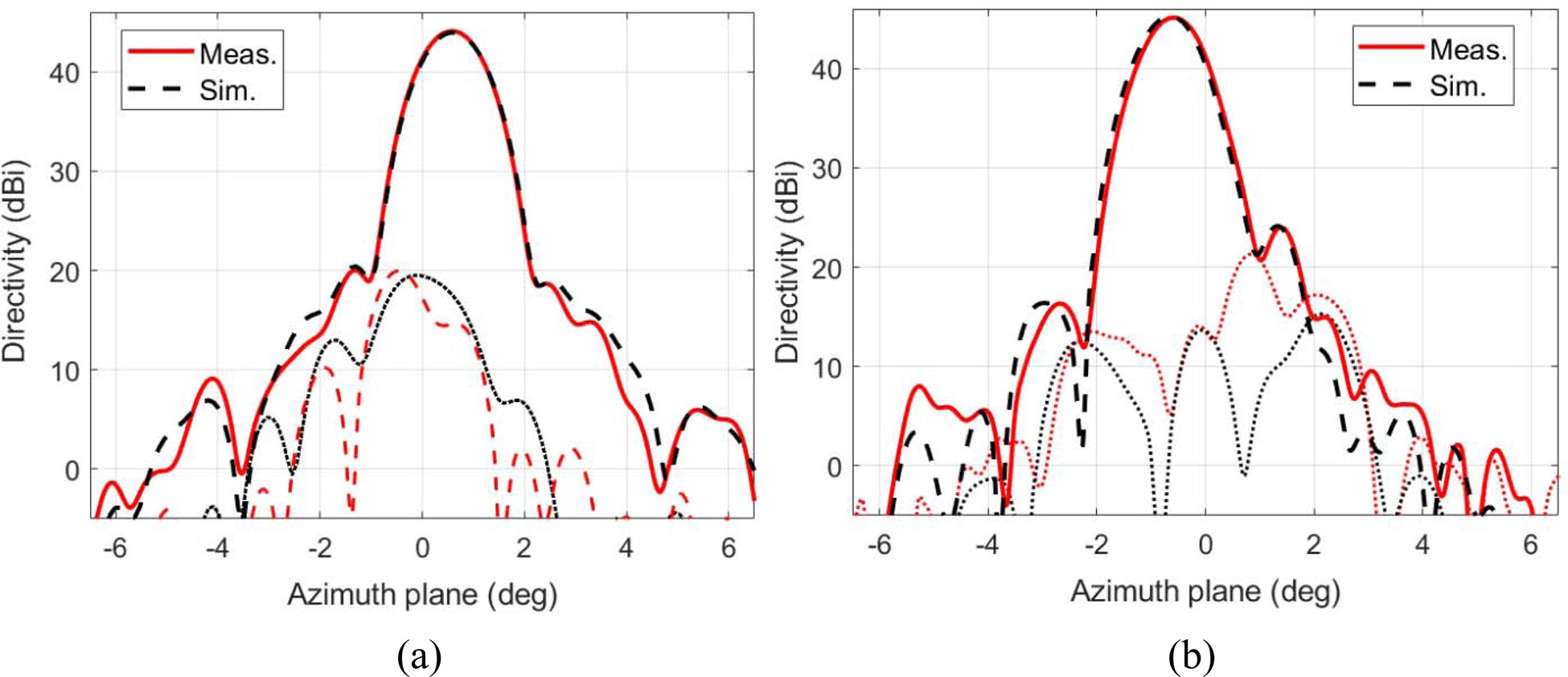
Fig. 19. Cut of the measured and simulated radiation patterns for the beam generated in RHCP by one feed at (a) 19.7 GHz and (b) 29.5 GHz.
Conclusion
A parabolic reflectarray that generates two spaced beams per feed has been proposed to generate half the required multi-spot coverage for HTS in Ka-band. The reflectarray operates by the VRT applied independently at 19.7 and 29.5 GHz, by rotating on each reflectarray cell two arcs and two sets of three parallel dipoles, respectively. The 1.8 m parabolic reflectarray has been designed cell by cell thanks to a replication process that generates an initial layout for the 62 654 cells from the design of only 564 cells. The simulated results show that the reflectarray antenna can generate 54 beams from 27 dual-CP feeds, simultaneously at 19.7 and 29.5 GHz. Two parabolic reflectarrays operating at slightly different frequencies could generate a complete four-color coverage from HTS, halving the number of antennas, from four reflectors to two reflectarrays, and the number of feed-chains required on board the satellite.
Acknowledgement
This work was supported by the Spanish Ministry of Science and Innovation and the Spanish Research Agency within projects PID2020-113979RB-C22 AEI/10.13039/501100011033, PID2020-114172RB-C21-2 AEI/10.13039/501100011033, and PDC2021-120959-C21/AEI/10.13039/501100011033, the last one funded by the recovery plan for Europe NextGenerationEU.
 Daniel Martinez-de-Rioja received the B.Sc., M.Sc., and Ph.D. degrees in telecommunication engineering from the Universidad Politécnica de Madrid (UPM), Madrid, Spain, in 2016, 2018, and 2021, respectively. Currently, he is a Visitant Researcher at the Department of Electrical, Electronic, Computer and Systems Engineering, University of Oviedo, Oviedo, Spain, after receiving a postdoctoral fellowship from the Spanish Ministry of Universities. His current research interests include the design of dual frequency, dual-polarization, and multibeam reflectarray antennas for satellite applications in Ka-bands.
 Eduardo Martinez-de-Rioja received the Telecommunication Engineer and Ph.D. degrees from the Universidad Politécnica de Madrid (UPM), Madrid, in 2014 and 2018, respectively. From 2015 to 2019, he was with the Applied Electromagnetics Group at UPM, as a Research Assistant. In 2016, he joined the Electrical and Computer Engineering Department, University of Toronto, Toronto, Canada, as a Visiting Ph.D. Student. Since 2019, he is an Assistant Professor at the Department of Signal Theory and Communications and Telematic Systems and Computing, Universidad Rey Juan Carlos, Madrid, Spain. His research interests include the design of dual-frequency, dual-polarization, and multibeam reflectarray antennas for satellite applications in Ku and Ka bands.
 Yolanda Rodriguez-Vaqueiro received the B.S. and M.S. degrees in electrical engineering from the University of Vigo, Vigo, Spain, in December 2009, and the Ph.D. degree in electrical engineering from Northeastern University, Boston, MA, USA, in May 2015. She was a Junior Researcher with the University of Vigo, where she is currently a Postdoctoral Researcher affiliated with AtlantTIC Research Center. In 2011, she received a Research Assistant grant from the Awareness and Localization of Explosive Related Threats (ALERT) Center of Excellence, Northeastern University. Dr. Rodriguez-Vaqueiro was recognized with the “Research-Impact Award” by the Electrical and Computer Engineering Department, Northeastern University. In 2018, she was awarded with a “Juan de la Cierva” grant by the Spanish Ministry of Education.
 Jose A.Encinar received the Electrical Engineering degree and the Ph.D. degree from the Universidad Politécnica de Madrid (UPM), Madrid, in 1979 and 1985, respectively. He was with the Laboratory of Electromagnetics and Acoustics, École Polytechnique Fédérale de Lausanne, Lausanne, Switzerland, in 1996, and with the Institute of Electronics, Communication and Information Technology, Queen's University Belfast, Belfast, UK, in 2006 and 2011, as a Visiting Professor. Since 1980, he has been with the Applied Electromagnetism Group, UPM. Since 1987, he has been a Post-Doctoral Fellow of the NATO Science Program with Polytechnic University, New York City, NY, USA. Since 1991, he has been a Professor with the Electromagnetism and Circuit Theory Department, UPM. His current research interests include numerical techniques for the analysis of multilayered periodic structures, design of frequency-selective surfaces, printed arrays, and reflectarrays.
 Antonio Pino received the M.S. and Ph.D. degrees in telecommunications engineering from the Polytechnic University of Madrid (UPM), Madrid, in 1985 and 1989, respectively. He joined the Department of Technologies of Communications, University of Vigo, Vigo, Spain, as an Associate Professor in 1989, and became a Full Professor in 1994. During 1993, he was a Visiting Researcher with the Center for Electromagnetics Research, Northeastern University, Boston, MA, USA. From 2006 to 2010, he was the Vice-Rector with Academic Organization and Faculty, University of Vigo, and since 2014, he has been the Director with the International Doctoral School, University of Vigo. He has authored more than 100 technical papers in journal and conferences and has been an Advisor of 14 Ph.D. thesis. His research interests include reflectarray and shaped reflector antennas for communication and radar applications, high-frequency backscattering, computational electromagnetics, and terahertz technology.
 Marcos Arias received the Telecommunications Engineer degree and the Ph.D. degree in telecommunication engineering from the University of Vigo, Vigo, in 1991 and 1997, respectively. He has been an Associate Professor since 1998 and has been with the Department of Signal Theory and Communications teaching radiocommunications, University of Vigo, since 1992. He has worked in projects related with antennas for satellite and radioastronomy, communication systems such Digital Video Broadcasting-Terrestrial, Local Multipoint Distribution System, and Universal Mobile Telecommunications System, and system engineering.
 Manuel Arrebola received the M.Sc. degree in telecommunication engineering from the University of Málaga, Málaga, Spain, in 2002, and the Ph.D. degree from the Technical University of Madrid (UPM), Madrid, Spain, in 2008. In 2005, he was with the Microwave Techniques Department, Universität Ulm, Germany, as a Visiting Scholar. In 2007, he joined the Electrical Engineering Department, Universidad de Oviedo, Gijón, Spain, where he is currently an Associate Professor. In 2009, he was with the European Space Research and Technology Centre, European Space Agency, The Netherlands. In 2018, he was with the Edward S.Rogers Sr. Department of Electrical and Computer Engineering, University of Toronto, Canada, as a Visiting Professor. His current research interests include the development of efficient analysis, design and optimization techniques of reflectarray and transmitarray antennas both in near and far fields.
 Giovanni Toso received the Laurea Degree, the Ph.D., and the Post Doctoral Fellowship from the University of Florence, Italy, in 1992, 1995, and 1999. In 1996, he was a visiting scientist at the Laboratoire d'Optique Electromagnétique, Marseille (France). In 1999, he was a visiting scientist at the University of California in Los Angeles, he received a scholarship from Alenia Spazio (Rome, Italy), and he has been appointed researcher in a Radio Astronomy Observatory of the Italian National Council of Researches. Since 2000 he is with the Antenna and Submillimeter Waves Section of the European Space Agency, ESA ESTEC, Noordwijk, The Netherlands. He has been initiating and contributing to several R&D activities on satellite antennas based on arrays, reflectarrays, lenses, and reflectors.


 Open access