


1. Introduction
Dust particles are commonly observed during the tokamak operations (Rubel et al. Reference Rubel, Cecconello, Malmberg, Sergienko, Biel, Drake, Hedqvist, Huber and Philipps2001; Rudakov et al. Reference Rudakov, West, Wong, Brooks, Evans, Fenstermacher, Groth, Krasheninnikov, Lasnier and McLean2007; Hong et al. Reference Hong, Grisolia, Rohde and Monier-Garbet2010; Huang et al. Reference Huang, Yan, Feng, Cheng, Tomita, Liu, Gao, Zhong, Jiang and Yang2015). For example, tungsten grains (dust particles) originating from the plasma–surface interactions (PSI) cause the degradation of plasma parameters and even result in plasma disruptions (Gao et al. Reference Gao, Ding, Xie, Zeng, Zhang, Wang, Li, Zhu, Yan and Chen2020). As the operating parameters of tokamaks become higher, the physics of dust particles in tokamaks attracts much attention, due to several reasons (Krasheninnikov, Smirnov & Rudakov Reference Krasheninnikov, Smirnov and Rudakov2011) as listed below. First, the generated dust particles from the PSI greatly affect the plasma discharge, even resulting in the serious damage or the explosion of the tokamak (Roth et al. Reference Roth, Tsitrone, Loarte, Loarer, Counsell, Neu, Philipps, Brezinsek, Lehnen and Coad2009). Second, the toxicity and radioactivity of dust particles are big concerns to the tokamak maintenance team (Girard et al. Reference Girard, Garin, Taylor, Uzan-Elbez, Rodríguez-Rodrigo and Gulden2007, Reference Girard, Gulden, Kolbasov, Louzeiro Malaquias, Petti and Rodriguez-Rodrigo2008). Third, low-$Z$ cryogenic pellets, such as lithium and boron granules, are widely used during the tokamak operation to control edge localized modes, as well as the plasma density profiles, which are greatly beneficial for long-pulse H-mode discharges (Sun et al. Reference Sun, Diallo, Maingi, Qian, Tritz, Wang, Wang, Bortolon, Nagy and Zhang2021). In addition, some ‘particle probes’ are typically injected into the fusion plasma for the in situ diagnostic of the plasma in different regions (Wang & Ticos Reference Wang and Ticos2008; Taylor et al. Reference Taylor, Heim, Gonderman, Allain, Yang, Kaita, Roquemore, Skinner and Ellis2012). Therefore, it is of vital importance to design and build a robust dust diagnostic system, which is able to provide an accurate measurement of the three-dimensional (3-D) trajectories and also the ablation cloud of dust particles in tokamaks.
As a powerful in situ diagnostic of dust dynamics in tokamaks, high-speed cameras have widely been used in the past two decades (Krasheninnikov et al. Reference Krasheninnikov, Smirnov and Rudakov2011). For example, one fast camera is used to capture the time sequence of a dust cloud released during a discharge at TEXTOR (Rubel et al. Reference Rubel, Cecconello, Malmberg, Sergienko, Biel, Drake, Hedqvist, Huber and Philipps2001). Two cameras mounted at different locations are also used on tokamaks to capture more detailed information of dust dynamics (Roquemore et al. Reference Roquemore, Davis, Kaita, Skinner, Maqueda and Nishino2006, Reference Roquemore, Nishino, Skinner, Bush, Kaita, Maqueda, Davis, Pigarov and Krasheninnikov2007; Boeglin, Roquemore & Maqueda Reference Boeglin, Roquemore and Maqueda2008; De Temmerman et al. Reference De Temmerman, Bacharis, Dowling and Lisgo2010; Yang et al. Reference Yang, Krieger, Lunt, Brochard, Briancon, Neu, Dux, Janzer, Potzel and Pütterich2013; Shalpegin et al. Reference Shalpegin, Vignitchouk, Erofeev, Brochard, Litnovsky, Bozhenkov, Bykov, den Harder and Sergienko2015; Brochard et al. Reference Brochard, Rohde, Lunt, Suárez López, Shalpegin and Neu2019). Roquemore et al. (Reference Roquemore, Nishino, Skinner, Bush, Kaita, Maqueda, Davis, Pigarov and Krasheninnikov2007) used two synchronized cameras, mounted at two different locations on NSTX, to record the motion of dust particles, and as a result, the 3-D trajectories of dust particles in NSTX are obtained. A similar stereoscopic imaging system with two fast infrared cameras are also equipped on MAST (De Temmerman et al. Reference De Temmerman, Bacharis, Dowling and Lisgo2010), so that the mobilization and transport of carbon and tungsten particles around the divertor are observed. On ASDEX-U (Yang et al. Reference Yang, Krieger, Lunt, Brochard, Briancon, Neu, Dux, Janzer, Potzel and Pütterich2013), two fast visible range camera systems with the vertically and tangentially oriented viewing cones are installed to observe the 3-D trajectories of melted tungsten droplets around the divertor region. Shalpegin et al. (Reference Shalpegin, Vignitchouk, Erofeev, Brochard, Litnovsky, Bozhenkov, Bykov, den Harder and Sergienko2015) obtained the significant different 3-D trajectories of pre-characterized carbon and tungsten dust particles from the tracking analysis of the video data from the stereoscopic fast camera system on TEXTOR, which comprises two fast cameras for the side and bottom views. The orientation directions of the two cameras used for the dust observations above are perpendicular to each other, except for those on MAST in which the 3-D trajectories are obtained using a code with the accuracy of approximately $2\ {\rm {cm}}$ (De Temmerman et al. Reference De Temmerman, Bacharis, Dowling and Lisgo2010).
In fact, to obtain the 3-D coordinates using the stereocamera system, the perpendicular orientation directions of two cameras, as used by Roquemore et al. (Reference Roquemore, Nishino, Skinner, Bush, Kaita, Maqueda, Davis, Pigarov and Krasheninnikov2007), Yang et al. (Reference Yang, Krieger, Lunt, Brochard, Briancon, Neu, Dux, Janzer, Potzel and Pütterich2013) and Shalpegin et al. (Reference Shalpegin, Vignitchouk, Erofeev, Brochard, Litnovsky, Bozhenkov, Bykov, den Harder and Sergienko2015), are not necessary. From the principle of stereocameras (Brown Reference Brown1971; Ivanov et al. Reference Ivanov, Boissard, Chapron and Andrieu1995; Prasad & Jensen Reference Prasad and Jensen1995; Zhang Reference Zhang2000; Maddonni et al. Reference Maddonni, Chelle, Drouet and Andrieu2001; Luhmann et al. Reference Luhmann, Robson, Kyle and Harley2011), for any orientation directions of two cameras, the 3-D coordinates of the observed objects are always able to be determined by using the triangulation method; however, the accuracy is related to the orientation directions of two cameras. For example, on the stellarator of the Large Helical Device (Sakamoto & Yamada Reference Sakamoto and Yamada2005; Mishra et al. Reference Mishra, Sakamoto, Matsuyama, Motojima and Yamada2011), the angle between the orientation directions of the two cameras is $18^{\circ }$ , which is able to achieve a measurement uncertainty of ${\approx }30\ {\rm mm}$
 (Sakamoto & Yamada Reference Sakamoto and Yamada2005). During an extremely busy tokamak operation campaign with multiple experiments performed in parallel, it is too difficult to reserve two viewing ports for a long time to observe dust dynamics from two perpendicular directions, as was performed by Roquemore et al. (Reference Roquemore, Nishino, Skinner, Bush, Kaita, Maqueda, Davis, Pigarov and Krasheninnikov2007), De Temmerman et al. (Reference De Temmerman, Bacharis, Dowling and Lisgo2010), Yang et al. (Reference Yang, Krieger, Lunt, Brochard, Briancon, Neu, Dux, Janzer, Potzel and Pütterich2013) and Shalpegin et al. (Reference Shalpegin, Vignitchouk, Erofeev, Brochard, Litnovsky, Bozhenkov, Bykov, den Harder and Sergienko2015). Thus, we propose to design a new stereocamera system with two cameras on the HL-2A tokamak using only a single flange, so that the long time dust observation on the tokamak is more feasible. To quantify the systematic error of the stereocamera system under various conditions comparable to the future experiment on the HL-2A tokamak, we carry out the experimental investigation reported here. Our goal of this newly designed stereocamera system using a single flange is to achieve the 3-D reconstruction of dust particles with the accuracy level comparable to $2\ {\rm cm}$
 for the previous tokamak dust diagnostic systems (Sakamoto & Yamada Reference Sakamoto and Yamada2005; Roquemore et al. Reference Roquemore, Nishino, Skinner, Bush, Kaita, Maqueda, Davis, Pigarov and Krasheninnikov2007; De Temmerman et al. Reference De Temmerman, Bacharis, Dowling and Lisgo2010), or even better. Our main motivation is first to exploit the stereocamera technique to the tokamak system, and second to try to minimize the 3-D reconstruction error based on the limited hardware conditions inside tokamaks.
This paper is organized as follows. In § 2, we briefly introduce the stereocamera principle, as well as the sources of 3-D reconstruction systematic error. In § 3, we report our obtained conclusions on the 3-D reconstruction systematic error of the stereocamera under various operating conditions, which all can be achieved on the HL-2A tokamak. In § 4, we describe our design of the stereocamera system on the HL-2A tokamak, and also propose a set of practical procedures to optimize the accuracy of the stereocamera, based on the obtained conclusions in § 3. Finally, in § 5, we provide a brief summary.
2. Stereocamera principle
In principle, the relationship between the 3-D coordinate of a certain point and the two-dimensional (2-D) coordinate of its image captured by a camera can be derived through the coordinate transformation and the perspective projection (Brown Reference Brown1971; Zhang Reference Zhang2000; Hartley & Zisserman Reference Hartley and Zisserman2004; Himpel, Buttenschön & Melzer Reference Himpel, Buttenschön and Melzer2011; Luhmann et al. Reference Luhmann, Robson, Kyle and Harley2011; Prince Reference Prince2012; Himpel & Melzer Reference Himpel and Melzer2019). As shown in figure 1, a point ‘C’, with the coordinate of $(x_C, y_C, z_C)$ in the lab frame, is captured by camera 1, resulting in its image of ‘c’, with its relative location of $(u_c, v_c)$
 on the image plane of camera 1. The coordinates of all points (or objects) in camera 1's frame can be obtained directly from their coordinates in the lab frame, using the combination of one translational and one orientational transformations (Hartley & Zisserman Reference Hartley and Zisserman2004; Himpel et al. Reference Himpel, Buttenschön and Melzer2011; Prince Reference Prince2012; Himpel & Melzer Reference Himpel and Melzer2019). During the transformation from the lab to camera 1's frame, in total, there are only six degrees of freedom, or six parameters, three of which are the orientation angles, while the other three are the 3-D coordinates of camera 1 in the lab frame. After the coordinate of ‘C’ in camera 1's frame is determined, the location of its image ‘c’ on the image plane $(u_c, v_c)$
 can be determined from the perspective projection process, which only involves the intrinsic parameters of the camera, such as the focal length of the camera's lens, which are always known in our experiments. It is not convenient to directly measure these six transformation parameters precisely, so we use a different method to determine them, as we describe next.

Figure 1. Three-dimensional (3-D) reconstruction principle of the stereocamera, containing two cameras. In the first step, termed as the calibration, the calibration point (CP) in the 3-D space is projected on the 2-D image plane of the camera. This step can be regarded as the transformation of the CP's 3-D coordinate $(x_C, y_C, z_C)$ in the lab frame to the camera's frame, and then its 3-D coordinate in the camera's frame is projected to the image plane as $(u_c, v_c)$
 . This transformation is only the combination of the rotational and translational transformations, i.e. the function of the position and the orientation of the camera, with only six free parameters. Thus, in principle, if we have ${\ge }3$
 CPs with their precisely known 3-D coordinates, the position and orientation of the camera can be determined. In the second step, termed as the 3-D reconstruction, we use the determined position and orientation of each camera, combined with the measured point (MP) relative coordinates on the corresponding 2-D image plane, to calculate its 3-D coordinate in the lab frame. In fact, this second step can be regarded as the inverse procedure of the previous rotational and translational transformations in the first calibration step.
The procedure to determine these six transformation parameters of each camera is often called the stereocamera calibration. In this procedure, the key information is the known precise 3-D coordinates of points, which we term the calibration points (CPs). Since the image of each CP has the measured 2-D coordinates on the image plane, i.e. two independent values related to its positions in the two directions, like $(u_c, v_c)$ of ‘c’ in figure 1, in principle, the six transformation parameters can be determined from the images of at least three CPs. A greater number of CPs will result in a higher accuracy of the stereocamera calibration, as we verify in detail later.
After completing the calibration of each camera, we are able to reconstruct the 3-D coordinate of the measured point (MP) in the lab frame, which is visible by the two cameras. This 3-D reconstruction is to calculate the 3-D coordinate of the MP in the lab frame, based on the locations of its images on the two cameras (four independent values) combined with the determined twelve transformation parameters of the two cameras (six for each). Clearly, this 3-D reconstruction procedure is the inverse of the previous calibration. In figure 1, the image point ‘M’ captured by the two calibrated cameras are ‘${\rm {m}}_1$ ’ and ‘${\rm {m}}_{2}$
 ’, respectively. As a result, the 3-D coordinate of the image point ‘M’ can be determined from the two steps of the calibration first and then the reconstruction. In fact, after the reconstruction from only camera 1, the image of ‘${\rm {m}}_1$
 ’ is converted to a straight line through this image point, marked as ‘${\rm {ray}}\ 1$
 ’ in figure 1. In other words, all points in the straight line of ‘ray 1’ result in the same image point of ‘${\rm {m}}_{1}$
 ’. Similarly, another ray, marked as ‘ray 2’, is also determined from the reconstruction based on the image of ‘${\rm {m}}_{2}$
 ’ and the six transformation parameters of camera 2. Therefore, the 3-D coordinate of ‘${\rm {M}}$
 ’ is obtained as the intersection of these two rays.
Different from the geometric optics described above, the stereocamera contains various systematic errors. As one systematic error of stereocameras, the limited spatial resolution arises from the finite pixel size of the charge-coupled device (or complementary metal-oxide semiconductor). Within the solid angle range represented by the pyramid shown in figure 2(a), the images of all points inside this pyramid belong to the same pixel on the image plane. That is to say, the detailed information inside this pyramid is indistinguishable from the 2-D image taken by the stereocamera. This solid angle is completely determined by the pixel size and the focal length of the camera lens, i.e. the intrinsic parameters of the stereocamera. As a result, this solid angle is just the limit of the 3-D reconstruction accuracy of the stereocamera. In other words, in general, this absolute error of the 3-D reconstruction is larger for a farther away object, while smaller for a closer object.
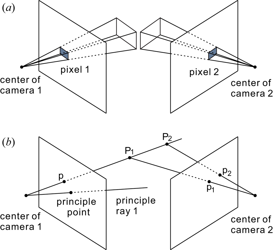
Figure 2. Sketch of the stereocamera's systematic errors due to the finite spatial resolution (a), and the image coincidence of all points on one ray (b). The finite pixel size limits the accuracy of the measured relative coordinates on the corresponding 2-D image plane, which is magnified further as the object distance increases, leading to the systematic errors in both the calibration and the 3-D reconstruction procedures. All points inside the rectangular pyramid in panel (a) are indistinguishable, indicating the lower limit of this error due to the finite pixel size. In panel (b), the images of points on one ray, such as ‘${\rm {P}}_{1}$ ’ and ‘${\rm {P}}_{2}$
 ’, in the 3-D space are both collapsed to one point ‘p’ on the 2-D image plane of camera 1. To distinguish these points, one more camera, located in a different position and orientated in a different direction, is necessary, so that the images of ‘${\rm {P}}_{1}$
 ’ and ‘${\rm {P}}_{2}$
 ’ on the image plane of camera 2, ‘${\rm {p}}_{1}$
 ’ and ‘${\rm {p}}_{2}$
 ’, are not overlapped any more. Although the perpendicular angle of the two principle rays of the two cameras is not necessary, this angle between the two principle rays does affect the stereocamera's systematic error.
In addition to the pixel size effect described above, the systematic error due to the image coincidence still cannot be completely avoided while using stereocameras. The image coincidence means that the images of all points on one ray are collapsed to the same position on the image plane, so that one has to completely rely on the other camera to distinguish them, as shown in figure 2(b). Clearly, in figure 2(b), ‘${\rm {P}}_{1}$ ’ and ‘${\rm {P}}_{2}$
 ’ are both mapped to ‘p’ on the image plane of camera 1. On the image plane of camera 2, these two points are mapped to ‘${\rm {p}}_{1}$
 ’ and ‘${\rm {p}}_{2}$
 ’, respectively. Thus, the calculated distance between ‘${\rm {P}}_{1}$
 ’ and ‘${\rm {P}}_{2}$
 ’ from the 3-D reconstruction is completely determined by the information captured by camera 2. To reduce the 3-D reconstruction error of ‘${\rm {P}}_{1}$
 ’ and ‘${\rm {P}}_{2}$
 ’, we should adjust the parameters of camera 2 to maximize the distance between their images of ${\rm {p}}_{1}$
 and ${\rm {p}}_{2}$
 . Thus, the optimized orientation angle of the two cameras should be $90^{\circ }$
 , i.e. the principle rays of the two cameras should be perpendicular to each other. Note, the principle ray of this camera refers to the ray from the camera that is perpendicular to the image plane. However, for some experiments, due to limitation of the hardware, such as on the HL-2A tokamak, the $90^{\circ }$
 angle of the two principle rays is not feasible. When the object distance is large enough, the lower limit of the stereocamera's systematic error arising from the two principle rays forming a smaller angle of $\theta$
 can be described as $1/\sin \theta$
 times the lowest systematic error of the $90^{\circ }$
 between two principle rays (Imagesystems, TEMA). Note, in addition to those described above, there are also systematic errors from the distortion effects of optical lenses, such as the pincushion or barrel distortions, which in principle may be improved by using dense enough calibration points (Zhang Reference Zhang2000; Ricolfe-Viala & Sánchez-Salmerón Reference Ricolfe-Viala and Sánchez-Salmerón2011), which are beyond the scope of our current investigation reported here.
3. Experiment and results
To quantitatively analyse the 3-D reconstruction accuracy in the future experiments on the HL-2A tokamak, we perform our current experiment using the apparatus whose parameters can be easily controlled. All conditions and parameters in our experimental investigation, such as the object distance of MPs, the angle between the two camera principle rays, the focal length of the lens and the calibration object, are all comparable and feasible on the HL-2A tokamak. Our stereocamera comprises two digital cameras, Basler acA1300-60gm and acA1300-75gm, which are both installed with the same type of lens, Computar M1614-MP2, with the focal length of $16\ {\rm mm}$ . The operations of the stereocamera calibration and the 3-D reconstruction are assisted by the software of TEMA (Imagesystems, TEMA). The calibration target comprises three mutually perpendicular planes with checkerboard patterns, as shown in figure 3. Each plane contains $20 \times 20$
 grids, with the size of each grid of $20\ {\rm mm} \times 20\ {\rm mm}$
 . Note, we set the f-number of each Computar M1614-MP2 lens as its lowest value of 1.4 during the experiment to achieve higher quality captured images, and the corresponding depth of field is also suitable to mimic the dust observation environment on the HL-2A tokamak.

Figure 3. Experiment images for the 3-D reconstruction accuracy test while all CPs (a) and MPs (b) are all chosen on the $x$ –$z$
–$z$ plane of the calibration target. We use three mutually perpendicular planes, with checkerboard patterns, as the calibration target for all tests in this paper. All CPs and MPs are chosen as the square corners on the $x$
 –$z$
–$z$ of the calibration target, labelled as the crosses in panel (a) and the filled circles in panel (b), respectively. On the coordinate of the calibration target, the true locations of all grid points are known, which are used in the calibration and the latter 3-D reconstruction for the CPs and MPs, respectively. In panel (a), for each calibration procedure, we connect all CPs to one polygon, termed as the CP polygon, which describes the spatial occupation of CPs on the image plane of the camera. By varying the size of the CP polygon in panel (a) and then 3-D reconstruction of the coordinates of all MPs in panel (b), we can determine the variation trend of the systematic error of the stereocamera as the function of the spatial range of CPs.
This design of this calibration target has at least two advantages. First, the square corners on the planar checkerboard patterns are very distinctive with the black and white colours in the four quadrants, so that their exact centres can be easily determined within the accuracy of only approximately a few pixels. Second, due to the perpendicular design of the three planes and the precise grid size of each checkerboard, if the coordinate of one corner is assumed, the 3-D coordinates of all square corners are precisely determined. Thus, in our experimental investigation, first, we choose some of these square corners on the calibration target as the CPs to calibrate the stereocamera system. Next, in the second step, we reconstruct the 3-D coordinates of other chosen square corners on the calibration target as the MPs. Note, here we reconstruct the coordinates of the MPs which do not move, or the static MPs, so that the accuracy of the stereocamera can be better quantified. Finally, by comparing the 3-D reconstructed positions of these MPs with their true positions, the systematic error of the stereocamera in the 3-D reconstruction can be expressed as

Here, $\boldsymbol {R}_i$ is the true position of the $i$
 th MP, $\boldsymbol {r}_i$
 is the determined position from the 3-D reconstruction of the stereocamera and $n$
 is total number of analysed MPs, respectively.
Using the calibration target to vary other conditions or parameters of the stereocamera system, we quantify the 3-D reconstruction systematic error of the stereocamera to determine the relationship between the 3-D reconstruction error and the parameters/conditions of the stereocamera. The parameters/conditions of minimizing the 3-D reconstruction error would be obtained from our experiments, and then be used as the guidelines in the design and operation of the stereocamera on the HL-2A tokamak. To easily quantify the region occupied by all CPs in the field-of-view (FOV) of one camera, we introduce a concept of the CP polygon, which is obtained by connecting the images of all CPs on the image plane during one calibration procedure. Note, while viewing from the camera, the size of the CP polygon is roughly proportional to the solid angle of the region that all CPs occupy. In § 3.1, we study the relationship between the 3-D reconstruction error and the CP polygon size in the calibration procedure. In § 3.2, we vary the range of the CP object distance to investigate its influence on the 3-D reconstruction error of the stereocamera. Finally, in § 3.3, we study the variation trend of the 3-D reconstruction error while the MP object distance varies. Our obtained results from these three experimental operations provide useful information of the 3-D reconstruction error of the stereocamera, which we incorporate into the design of the stereocamera on the HL-2A tokamak to maximize its capability in the future.
3.1. CP polygon size
As the first step of the stereocamera operation, the calibration procedure plays a critical role in its 3-D reconstruction accuracy. In the calibration procedure of the stereocamera, we need at least 3 CPs with their precisely known 3-D coordinates. As shown in figure 3(a), we name the polygon formed by these CPs as the CP polygon. Clearly, the size of the CP polygon is able to quantitatively describe the region occupied by all of these CPs in the FOV of the camera. To study the relationship between 3-D reconstruction error and the CP polygon size, we perform seven independent runs using the calibration target in three steps. First, we calibrate the stereocamera using four CPs, as shown in figure 3(a), where seven polygons correspond to seven independent runs. Second, according to the calibrated parameters, we reconstruct the 3-D coordinates of MPs, as the 36 corners of the filled circles shown in figure 3(b). Finally, we calculate the error of 3-D reconstruction using (3.1) by substituting the obtained 3-D coordinates of 36 MPs in figure 3(b) and their true positions.
In fact, in addition to using only four CPs, we also perform further runs using the same CP polygon with either five or eight CPs. For the five CPs, in addition to the four corners of each CP polygon in figure 3(a), we also use its centre as the fifth CP. For the eight CPs, in addition to the four corners, we also use the midpoint of each polygon side as the four additional CPs. Thus, we are able to calibrate the stereocamera using different CP numbers in each calibration procedure, while keeping the CP polygon size unchanged.
From figure 4(a), as the area of the CP polygon increases, the obtained 3-D reconstruction error of the stereocamera decreases monotonically. That is to say, to achieve a higher accuracy of the 3-D reconstruction, in the calibration procedure, we should choose CPs that occupy a relatively larger area on the image plane. Furthermore, we also find that for the same CP polygon, the 3-D reconstruction error from four CPs is roughly the same level as those from either five CPs or eight CPs. It seems that if the CP polygon is unchanged, additional chosen CPs within this CP polygon on the same plane do not improve the 3-D reconstruction accuracy by much. In the future experiment, to reduce the systematic error of the stereocamera, we should choose CPs occupying the area on an image plane as large as possible. Note, in the horizontal axis of figure 4, the sizes of the CP polygons from the views of the two cameras are slightly different, so that the data in the horizontal axis presented are the average value from the two cameras.

Figure 4. Obtained 3-D reconstruction error of the stereocamera as the function of the CP polygon size and the CP number (a), and the error magnitude in the three directions (b) for the CP number of four. The 3-D reconstruction error of the MP positions is determined by the averaged difference between the calculated and true positions of all MPs. From panel (a), as the CP polygon area increases gradually, the 3-D reconstruction error diminishes monotonically, indicating that more CPs occupying a larger area are desired in the stereocamera operation. From panel (b), the errors in the $x$ and $z$
 direction are substantially smaller than that in the $y$
 direction, indicating that the accuracy along the principle ray is the poorest.
The variation trend of the 3-D reconstruction error in figure 4(a) can be explained from the stereocamera principle. As described in § 2, in the stereocamera calibration procedure, we determine the six transformation parameters of each camera. The accuracy of the input data of the 3-D coordinates for all CPs and their relative 2-D coordinates on the image plane play the most important role. However, as shown in figure 2(a), the finite pixel size limits this accuracy, for example, while determining the relative 2-D coordinates $(u_c, v_c)$ , typically its sub-pixel accuracy cannot be smaller than 10 % of one pixel (Feng, Goree & Liu Reference Feng, Goree and Liu2007, Reference Feng, Goree and Liu2011). For a larger CP polygon size, the distance between two CPs is much larger, as a result, while determining the six transformation parameters of each camera, the effect of this small uncertainty is greatly suppressed due to the much higher signal-to-noise ratio (SNR). However, if the CP polygon size is too small, the much lower SNR would introduce a much larger systematic error in the six transformation parameters of each camera, which definitely induces a larger 3-D reconstruction error. In figure 4(a), more chosen CPs from the same polygon are not helpful, which is reasonable because the SNR cannot be enhanced by choosing more CPs.
From figure 4(b), the 3-D reconstruction error of MPs is mainly dominated by the uncertainty in the $y$ direction. From our experiment setup shown in figure 3, the $y$
 axis is roughly along with the principle rays of the two cameras. As shown in figure 4(b), when the CP polygon is small, the reconstruction error in the $y$
 direction is approximately eight times higher than the error in the $x$
 or $z$
 directions. When the CP polygon is much larger, this ratio decreases slightly to approximately five, i.e. the reconstruction error in the $y$
 direction is still significantly larger than that in the other two directions. Clearly, as the CP polygon size increases gradually, the monotonic diminishing trend of the systematic errors in the three directions is exactly the same.
The difference in the magnitude of the reconstruction error in the three directions in figure 4(b) can also be explained from the stereocamera principle. From the experiment setup of figure 3, the actual square grids on the $x$ –$y$
–$y$ plane are compressed into very narrow rectangles on the image plane of the camera, due to the orientation of the camera. In other words, since the principle ray of the camera is roughly in the $y$
 direction for the current setup, the square grid arrangement in the $y$
 direction cannot be easily distinguished from the image captured by the camera. As shown in figure 3, for the square-grid image, the same length in the $x$
 and $z$
 directions occupies many more pixels than that in the $y$
 direction. Thus, the SNR of the image information in the $y$
 direction is much lower than that of the other two directions, leading to the much larger reconstruction error in the $y$
 direction, as shown in figure 4(b). In fact, if the angle between two principal rays $\theta$
 is not close to $90^{\circ }$
 , the reconstruction error along the principal ray is always larger, which is approximately $1/\sin \theta$
 times the accuracy in the other two directions (Imagesystems, TEMA).
The results presented above are completely based on the calibration procedure using all CPs on one plane of the calibration target. Our obtained results clearly indicate that the 3-D reconstruction error of the stereocamera is dominated by the error in the direction perpendicular to the plane containing these CPs. Next, instead of choosing CPs only on one plane, we choose CPs in different locations in all of the three directions, as presented next.
3.2. CP object distance range
As a further test of the stereocamera operation, we quantify the reconstruction error of the stereocamera, using more CPs distributed widely in the three directions. Compared with § 3.1, in this subsection, we mainly focus on the accuracy of the stereocamera while varying the range of the object distances of the chosen CPs, as shown in figure 5(a). To quantify the 3-D reconstruction error in different regions, we select 60 MPs on the two perpendicular planes of the calibration target, 24 and 36 on the $x$ –$z$
–$z$ and $x$
 –$y$
–$y$ planes, respectively, as shown in figure 5(b). During the calibration procedure, we always choose seven CPs for all of the six independent runs. As shown in figure 5(a), in run 1, the seven square corners labelled as the crosses on the $x$
 –$z$
–$z$ plane are all chosen as the CPs. In the other five runs, the chosen seven CPs are on the two planes of $x$
 –$z$
–$z$ and $x$
 –$y$
–$y$ , as shown in figure 5(a). In fact, for each run, six of the seven CPs always form a rectangle sliding around the $z$
 –$y$
–$y$ corner, as shown by the side view in the inset of figure 5(a). Clearly, for the current chosen CPs from run 1 to run 6, the object distance range of the CPs increases gradually. Note, while viewing from the camera, the CP polygon size is always approximately 15 % of the FOV for all of the 6 runs here.

Figure 5. Experiment images for the 3-D reconstruction accuracy test while CPs (a) and MPs (b) are distributed on the $x$ –$z$
–$z$ and $x$
 –$y$
–$y$ planes of the calibration target. For each of the six runs, during the calibration step, we choose CPs on the two perpendicular planes, so that the resulting CP polygon on the camera's image plane has nearly the same area. The inset in the lower left corner of panel (a) indicates the side view of the CP polygon and the camera's orientation. Clearly, for all of the runs here, while viewing from the camera, the chosen CPs form the CP polygons with nearly the same size but with different object distance ranges. Using the stereocamera's calibrated information from panel(a) of each run, we reconstruct the 3-D coordinates of all MPs in panel (b), and then compare with their true coordinates to obtain the error variation as the CP object distance range changes.
From figure 6(a), the obtained reconstruction error is substantially reduced when the object distance range of the CPs is increased. As the object distance range of the CPs gradually increases, the 3-D reconstruction error for the 36 MPs on the $x$ –$y$
–$y$ plane drops from ${>}3.0\ {\rm mm}$
 to ${<}1.5\ {\rm mm}$
 , deceasing by more than one half of its initial value. For the 24 MPs on the $x$
 –$z$
–$z$ plane, the general diminishing trend of their reconstruction error with the increasing object distance range of the CPs is also clear. Of course, the dropping magnitude of the reconstruction error on the $x$
 –$z$
–$z$ plane is not as large as that on the $x$
 –$y$
–$y$ plane, since its initial error is already small enough, only ${\approx }1.2\ {\rm mm}$
 . From figure 6(a), it seems that for the current CP polygon size, the accuracy of our stereocamera system is only just approximately $1\ {\rm mm}$
 .
.

Figure 6. Variation trend of 3-D reconstruction error as the CP object distance range increases (a) and the error components in the three directions (b). From panel (a), when the CP object distance range increases, the error of the 3-D reconstruction is greatly reduced on the $x$ –$y$
–$y$ plane, and slightly reduced on the $x$
 –$z$
–$z$ plane, using the same calibrated information of the stereocamera. From panel (b), the 3-D reconstruction error mainly comes from that in the $y$
 direction, and the variation trend of the error in each direction is the same as that of the total error in panel (a). The results here indicate that, to achieve the more accurate 3-D reconstruction, a sufficient CP object distance range for the stereocamera is necessary.
The variation trend of the 3-D reconstruction error in figure 6(a) can be explained by the stereocamera principle using the CPs with the different distribution range along the $y$ direction. In this test, from the inset of figure 6(a), the spatial range of all chosen CPs along the $y$
 direction can be roughly described as the object distance range of the CPs from the orientation of the camera, simply the horizontal axis of figure 6. As mentioned in § 3.1, while the chosen CPs occupy a larger region in the $y$
 direction, their images on the image plane are able to enclose a bigger portion, i.e. the SNR of their image information used for the calibration procedure is enhanced. As a result, the accuracy of the stereocamera calibration can be improved using the CPs which occupy a larger range in the $y$
 direction, and the latter 3-D reconstruction error diminishes reasonably, especially for the reconstruction error on the $x$
 –$y$
–$y$ plane. For the $x$
 –$z$
–$z$ plane, the reconstruction error presented in figure 6(a) is close to the lower limit of the reconstruction error with the CP polygon size approximately 15 % of the FOV in figure 4(a), so that it just diminishes slightly as the occupied range of all CPs in the $y$
 direction increases. Note, as shown in figure 5, the camera is orientated roughly along the $y$
 direction leads to the more compressed images in the $y$
 direction, i.e. a lower SNR of the image information in the $x$
 –$y$
–$y$ and $y$
 –$z$
–$z$ planes. As a result, the reconstruction error on the $x$
 –$y$
–$y$ plane here is always higher than that on the $x$
 –$z$
–$z$ plane.
Clearly, in figure 6(b), the 3-D reconstruction error is still mainly dominated by the error in the $y$ direction. For the $x$
 –$y$
–$y$ plane, the reconstruction error in the $y$
 direction is always much higher than that in the other two directions. As the occupied range of all CPs in the $y$
 direction increases, the reconstruction error is substantially reduced in these three directions. For the $x$
 –$z$
–$z$ plane, the reconstruction error in the $y$
 direction is approximately $1\ {\rm mm}$
 , more than four times of the value in the other two directions, for all of the occupied ranges of all CPs in the $y$
 direction studied here. As mentioned above, since the reconstruction error is already close to the lower limit of the reconstruction error for the CP polygon size of 15 % of the FOV, only a briefly decreasing trend of the reconstruction error in the $y$
 direction is detected.
The variation trends of the 3-D reconstruction error in the three directions presented in figure 6(b) are reasonable from the orientation of the stereocamera. As mentioned above, from the orientation of the camera roughly in the $y$ direction, the images on the $x$
 –$y$
–$y$ and $y$
 –$z$
–$z$ planes are always compressed much. As a result, the corresponding calibration procedure and the latter reconstruction both contain larger systematic errors from the compressed information in the $y$
 direction. From run 1 to run 6, the distribution of the chosen CPs in the $y$
 direction is wider, so that the obtained reconstruction error is generally reduced for these three directions, for all MPs in all planes. Anyway, since the images of MPs on the $x$
 –$y$
–$y$ plane are still farther compressed as compared with those on the $x$
 –$z$
–$z$ plane, the reconstruction error on the $x$
 –$y$
–$y$ plane is still larger than the error on the $x$
 –$z$
–$z$ plane.
In this subsection, we find that the choice of CPs which are able to occupy a larger 3-D space is more desired during the stereocamera operation. The chosen CPs should occupy a larger region in three dimensions, which can be imaged by the stereocamera. One direction roughly along the principle ray of the camera can be described as the object distance range of the chosen CPs, as the $y$ direction in figure 5 above. The other two directions roughly perpendicular to the principle ray can be characterized by the CP polygon size, as we use in § 3.1, which is equivalent to the solid angle occupied by these CPs. After the stereocamera calibration is finished, we carry out a further test to quantify the 3-D reconstruction error in a much wider region, as presented next.
3.3. Object locations
To mimic the typical operation of the stereocamera, after the calibration procedure is finished using the calibration target at one location, we move the objects (also on the calibration target) to different locations to reconstruct the coordinates of MPs at different new locations. In the first run, we place the calibration target in the initial location, so that its original distance is $75\ {\rm cm}$ from the stereocamera, as shown in figure 7(a). At first, we calibrate the stereocamera using the chosen seven CPs, marked as the crosses in figure 7(a). Next, we reconstruct the 3-D coordinates of four MPs, marked as the hollow squares there. Then, we move the calibration target to 11 different locations, with the distance of the original point varying from $55\ {\rm cm}$
 to $115\ {\rm cm}$
 . At each new location, we always perform 3-D reconstruction of these selected MPs on the calibration target, using the calibration parameters determined at the initial location of $75\ {\rm cm}$
 . At these new locations, unlike the previous tests in § 3.1 and § 3.2, we do not perform the calibration procedure any more. As a result, the true coordinates of these MPs cannot be determined directly from the CPs any more. However, the relative distances between these MPs should not be changed any more, no matter where the calibration target is located. To characterize the 3-D reconstruction accuracy, we calculate the relative distances between the six pairs of these four MPs, using their obtained coordinates from the 3-D reconstruction, and then choose the averaged error of these six relative distances as the diagnostic of the stereocamera error. This test is very similar to the typical operation of the stereocamera during experiments, and the 3-D reconstruction error can also be quantified in a much wider region. To make a comparison, in addition to the initial location of $75\ {\rm cm}$
 , we also perform another test for the initial calibration procedure at $115\ {\rm cm}$
 from the stereocamera, as shown in figure 7(b), with the similar latter 3-D reconstruction of all MPs at different locations and the error quantification procedure.

Figure 7. Experiment images for the 3-D reconstruction accuracy test when the distance from the origin of the calibration target to the stereocamera is set as $75\ {\rm cm}$ (a) and $115\ {\rm cm}$
 (b), respectively, for the two runs studied here. For each run, we choose the seven square corners as CPs, marked as crosses, to calibrate the stereocamera. Then, we move the calibration target to a few new locations, and directly reconstruct the coordinates of four MPs, marked as hollow squares, using the calibrated parameters at the initial location of each run. Since we do not calibrate the stereocamera again at the new locations, the errors of the reconstructed coordinates of these four MPs are not known. However, the relative distances between these MPs should be unchanged, no matter where the calibration target is located. To characterize the 3-D reconstruction accuracy, here we use the averaged error of the six relative distances of these four MPs. Using this method, the 3-D reconstruction error can be quantified in a much wider region.
Figure 8 presents the variation of the 3-D reconstruction error as the function of the distance of the object (still the calibration target) from the stereocamera, while using the initial calibration parameter. For the first run of the initial location of $75\ {\rm cm}$ for the origin of the calibration target, the calculated length error reaches its minimum of ${\approx }0.2\ {\rm mm}$
 while the origin of the calibration target is $75\ {\rm cm}$
 away from the camera. That is to say, only at the location where we calibrate the stereocamera is its systematic error the smallest. When we move the object either closer or farther away from the camera, its systematic error always increases monotonically. For the second run with the calibration procedure performed for the origin of the calibration target at a distance of $115\ {\rm cm}$
 , the systematic error also roughly reaches its minimum of ${\approx }0.2\ {\rm mm}$
 when the calibration target is moved ${\gtrsim }95\ {\rm cm}$
 away from the stereocamera, including its initial location for the calibration procedure. From the results of these two runs, clearly, the systematic error of the stereocamera is always smaller for MPs closer to CPs, while for MPs farther away from CPs, their 3-D reconstruction error tends to be larger.

Figure 8. Variation of the calculated length error from the 3-D reconstruction as the location of the calibration target varies. Clearly, for the first run, when the distance of the calibration target is $75\ {\rm cm}$ , simply its location during the calibration procedure, the error of calculated length reaches its minimum, only ${\approx }0.2\ {\rm mm}$
 . For the second run, the calculated length error is reduced to a low level of ${\approx }0.2\ {\rm mm}$
 when the distance of the calibration target is ${\gtrsim }95\ {\rm cm}$
 , roughly the range where the calibration target is initially placed for the calibration. The results from these two runs clearly indicate that the 3-D reconstruction is much more accurate for MPs around CPs. As a result, choosing more CPs around the main observed region is helpful in improving the accuracy of the stereocamera.
Note, the current diagnostic of the stereocamera error, where we use the averaged error of the six chosen relative distances, may not completely and precisely reflect the global variation of the systematic error. For example, our chosen CPs and MPs are only concentrated in a portion of the FOV, as shown in figure 7, especially for figure 7(b). However, the main variation trend of the systematic error in figure 8 is still reliable.
The results in figure 8 can be understood from the reconstruction principle of the stereocamera for MPs. As presented in § 2, the 3-D reconstruction of MPs can be regarded as the inverse process of the calibration using CPs. In the calibration procedure, all six transformation parameters of each camera are all derived from the chosen CPs. Clearly, these transformation parameters contain the systematic error, due to some uncertainties, for example, from the measured locations of the CPs on the image plane. Then, in the second step, using the derived 12 transformation parameters of the two cameras, the 3-D coordinates of the MPs are calculated. If the MPs are closer to CPs, the error of the obtained coordinates of these MPs should be smaller, since the precisely known true positions of CPs, i.e. the reference points, are just nearby. However, if the MPs are farther away from the CPs, the error in the calculation of the 3-D coordinates for these MPs can be regarded as the deviation of their 3-D locations farther away from the determined transformation parameters from a limited region containing these CPs. Thus, for the MPs far away from the CPs, the error of the 3-D coordinates of the MPs from these transformation parameters tends to be exaggerated further away without any corrections at all. From these results, to improve the accuracy of the stereocamera, around the main observed region, choosing more CPs should be helpful.
In this section, we mainly focus on the strategy to improve the 3-D reconstruction accuracy of the stereocamera. Our obtained results indicate that a larger CP polygon, a wider range occupied by CPs and placing CPs closer to the observed region are all helpful to reduce the systematic error of the stereocamera. Then we use these conclusions as the guidelines while designing a stereocamera system from scratch on the HL-2A tokamak, as presented in the next section.
4. Practical optimization
The motivation of our 3-D reconstruction accuracy experiments performed above is to provide constructive guidelines in designing a new stereocamera system on the HL-2A tokamak, which will be used to observe the 3-D trajectories and the ablation cloud (Sun et al. Reference Sun, Baldwin, Xu, Wang, Hu, Maingi, Romero-Talamas and Oschwald2018) of dust particles in the tokamak. In addition to the passive observation of dust particles, we mainly focus on the observation of dust particles which are introduced, for example, from the injection port, as shown in figure 9. After being accelerated to ${\approx }100\ {\rm {m}}\ {\rm s}^{-1}$ in the direction along the major radial direction of the vessel, these dust particles are injected into the main plasma body, so that they are negatively charged immediately. As a result, as they penetrate along the minor radial direction, these dust particles are also able to move along the magnetic axis, due to the ion drag force in the main plasma body, in the direction of the arrow shown in figure 9. Our designed stereocamera system is intended to capture the detailed 3-D trajectories and the ablation cloud of dust particles as much as possible, based on the current hardware conditions of the HL-2A tokamak, therefore, the positions and orientations of cameras are crucial. Note, although the dust size evolution during the dust ablation procedure is crucial in tokamak dust investigations, the dust size cannot be directly determined from the stereocamera system, as a result, trajectories of ablating dust particles from computer simulations can be compared with the corresponding experimental observations for quantitative investigations (Liu et al. Reference Liu, Ding, Xu, Li, Deng, Sun, Wang and Feng2021).

Figure 9. Sketch of the stereocamera design for the dust trajectory observation on the HL-2A tokamak. Since the charged dust particles would move along the magnetic axis direction, the stereocamera should be mounted at the location where the dust injection port and the immediate trajectories of dust particles (mainly along with the magnetic axis direction for charged grains) can be both observed. The two cameras are orientated to the directions pointing to the injection port, with the sufficient common FOV. The angle of the two principle rays of the two cameras should be set large enough to improve the accuracy of the 3-D reconstruction. To avoid the exposure of the extreme plasma conditions inside the HL-2A tokamak, we propose to mount two in-vessel lenses connected with the imaging fibre cables to deliver images for two data recording cameras outside the vessel. Thus, we suggest that the two lenses inside the HL-2A tokamak should be placed up and down far apart, so that the angle between their principle rays reaches its possible maximum. By optimizing the calibration process following our suggestions from the experiment results above, the accuracy of the 3-D reconstruction would be further improved.
While designing the positions and orientations of the cameras, the stereocamera principles should be strictly obeyed. First, due to the limited hardware conditions, the minimum of two cameras are necessary for a stereocamera system. Second, the common FOV of the two cameras should include the poloidal cross-sections of the tokamak around the injection port, so that the initial motion of the injected dust particles can be clearly observed. Third, from § 2, to reduce the systematic error of the 3-D reconstruction of the stereocamera system, the desired angle between the principle rays of the two cameras should be larger. Figure 9 presents our designed locations and orientations of the two cameras on the HL-2A tokamak. Clearly, to obtain the sufficient common FOV in the typical toroidal structure of the HL-2A tokamak, the two cameras are both orientated to the injection port, so that the detailed trajectories and the ablation of the injected dust particles can be observed from them. In addition, the two cameras are designed to be placed up and down as far apart as possible. In fact, in the HL-2A tokamak, the upper and lower cameras are designed to be close to the edge of the upper and lower divertors, respectively, i.e. they cannot be further apart any more. This up-and-down symmetrical placement also allows us to adjust the angle between the two principle rays of the cameras easily, while ensuring a suitable common FOV, as described above. Another advantage of the current locations and orientations of the two cameras is that the latter trajectories of dust particles as they move along the magnetic axis can be mostly captured by the two cameras. Due to the extreme plasma conditions inside the HL-2A tokamak, instead of two cameras, in fact, we mount two in-vessel lenses there connected with two large-cross-section imaging fibre cables to deliver images, from those two orientations at those two locations, to the end for the two synchronized cameras, which are operated outside the vessel for the data recording.
After installing the cameras, we are also able to perform a set of practical procedures to optimize the 3-D reconstruction accuracy of the stereocamera, based on the experiment results in § 3. Before the experiment campaign, using the calibration target in figure 3, we calibrate the designed stereocamera on the HL-2A tokamak following the strategies below to optimize the 3-D reconstruction accuracy. First, the chosen CPs should be distributed in a large enough area on the camera's image plane, i.e. these CPs are able to form a large enough CP polygon so that the effect of position uncertainty of the CPs on the image plane would be well suppressed due to a high SNR, as described in § 3.1. Second, the calibration target composed of three $40\ {\rm cm} \times 40\ {\rm cm}$ checkerboards is large enough for the HL-2A tokamak, so that we are able to select more CPs spanning a wide object distance range, further improving the reconstruction accuracy of the stereocamera, as described in § 3.2. Third, we use a large calibration target to cover enough spatial region with a higher accuracy, and place the calibration target at the main proposed observation region, for example, where dust particles are injected. Thus, around this main observation region, we are able to obtain the best 3-D reconstruction accuracy, according to § 3.3. Instead of involving the adjustment of the stereocamera hardware, these practical optimization steps just provide some guidelines of operating the stereocamera to help researchers achieve the best 3-D reconstruction accuracy.
5. Summary
In summary, we carry out the experimental investigation of the stereocamera's 3-D reconstruction error, which is intended to guide the observation of the 3-D trajectories and the ablation cloud of dust particles on the HL-2A tokamak. From our experimental results, we find that there are at least three factors that are able to significantly reduce the systematic error of the 3-D reconstruction of the stereocamera. The first one is the area enclosed by the image points of the chosen CPs on the camera's image plane, which can be quantitatively described as the CP polygon size, as described in § 3.1. Our experimental results clearly indicate that, as the CP polygon size increases, the 3-D reconstruction systematic error of the stereocamera diminishes monotonically. The second factor is the object distance range of the chosen CPs. When the range of the object distances of CPs is wider, the 3-D reconstruction systematic error of the stereocamera tends to be smaller. In fact, these two factors mean that the chosen CPs should occupy a large enough region in three dimensions to suppress the effect of position uncertainty of the CPs on the image plane. Finally, the accuracy of 3-D reconstruction is the highest when the CPs are located nearby. Thus, we should use a larger calibration target, and place it around the main proposed observation region. Following the stereocamera principle, we design a stereocamera system on the HL-2A tokamak, exploiting the current HL-2A hardware conditions. Then, based on the experimental results above, we propose a set of practical procedures or guidelines to optimize the operation of the stereocamera to reduce the 3-D reconstruction error, which are applicable to other magnetic fusion devices.
Acknowledgments
This work was supported by National MCF Energy R&D Program of China No. 2018YFE0310100 and the corresponding Supporting Project from the Suzhou Science and Technology Bureau, the 1000 Youth Talents Plan, the startup funds from Soochow University and the Priority Academic Program Development (PAPD) of Jiangsu Higher Education Institutions.
Editor Edward Thomas, Jr. thanks the referees for their advice in evaluating this article.
Declaration of interests
The authors report no conflict of interest.
Data availability
The data that support the findings of this study are available from the corresponding author upon reasonable request.


