


1 Introduction
In the past several years, there has been significant progress in developing femtosecond high-power laser systems (HPLSs) by using a chirped pulse amplification (CPA) technique in combination with laser media having broad emission spectral bandwidth[ Reference Strickland and Mourou 1 ] and by using optical parametric chirped pulse amplification (OPCPA) in nonlinear crystals with broad parametric gain bandwidth[ Reference Dubietis, Jonusauskas and Piskarskas 2 ]. Several petawatt (PW)-class femtosecond laser systems have been demonstrated as reported in the literature[ 3–13 ].
The first PW laser was based on a hybrid Ti:sapphire–Nd:glass laser system[ Reference Perry, Pennington, Stuart, Tietbohl, Britten, Brown, Herman, Golick, Kartz, Miller, Powell, Vergino and Yanovsky 3 ]. Later, another hybrid PW-class laser, with hundred-femtosecond pulse duration, has been developed by combining OPCPA in beta barium borate (BBO) and yttrium calcium oxyborate (YCOB) nonlinear crystals with kilojoule pulse energy amplification in Nd-doped mixed glasses[ Reference Gaul, Martinez, Blakeney, Jochmann, Ringuette, Hammond, Borger, Escamilla, Douglas, Henderson, Dyer, Erlandson, Cross, Caird, Ebbers and Ditmire 6 ].
PW peak power pulses have been also obtained in all-Ti:sapphire systems, which amplify stretched laser pulses re-compressible to a few tens of femtoseconds duration, but with a significantly lower output pulse energy compared with Nd:glass lasers[ Reference Aoyama, Yamakawa, Akahane, Ma, Inoue, Ueda and Kiriyama 4 , Reference Sung, Lee, Yu, Jeong and Lee 5 ]. For a given pulse energy, the highest peak power can be obtained through compressor dispersion compensation and through maximization of the spectral bandwidth of the pulse. Gain narrowing and red-shifting of the pulse spectrum during pulse amplification contribute to the decrease of the spectral bandwidth of the chirped amplified pulse and, therefore, to the increase of the compressed output pulse duration[ Reference Giambruno, Radier, Rey and Chériaux 14 ]. Therefore, in order to preserve a broad amplification bandwidth, special techniques were used, such as cross-polarized wave (XPW) generation[ Reference Jullien, Albert, Burgy, Hamoniaux, Rousseau, Chambaret, Augé-Rochereau, Chériaux, Etchepare, Minkovski and Saltiel 15 , Reference Jullien, Rousseau, Mercier, Antonucci, Albert, Chériaux, Kourtev, Minkovski and Saltiel 16 ], spectrum management using spectral filters[ Reference Giambruno, Radier, Rey and Chériaux 14 ], and hybrid amplification in femtosecond laser systems, based on noncollinear OPCPA (NOPCPA) at the low-energy level in BBO crystals and CPA in large-aperture Ti:sapphire crystals at the high-energy level[ Reference Wang, Liu, Shen, Zhang, Teng and Wei 7 , Reference Sung, Lee, Yoo, Yoon, Lee, Yang, Son, Jang, Lee and Nam 10 , Reference Kiriyama, Pirozhkov, Nishiuchi, Fukada, Ogura, Sagisaka, Miyasaka, Mori, Sakaki, Dover, Kondo, Koga, Esirkepov, Kando and Kondo 13 ]. For the pulse to be compressed near its Fourier transform limit, flat spectral phase over a large bandwidth is required, and was obtained by the correction of high-order phase distortions using acousto-optic programmable dispersion filters (AOPDFs)[ Reference Verluise, Laude, Huignard, Tournois and Migus 17 , Reference Seres, Herzog, Seres, Kaplan and Spielmann 18 ].
More than 1022 W/cm2 peak power density can be obtained by tightly focusing, in few-micrometer diameter spots, PW femtosecond laser pulses. The ability to obtain such a small diameter focused beam, with a large percentage of pulse energy concentrated in the focal spot, depends on the beam wavefront quality, characterized by its Strehl ratio (SR)[ Reference Akahane, Ma, Fukuda, Aoyoma, Kiriyama, Sheldakova, Kudryashov and Yamakawa 19 ], where in the ideal case of a laser beam with a flat wavefront free of aberrations, SR = 1. The wavefront aberrations of the laser pulses, induced through the CPA laser system, can be corrected by deformable mirrors, usually installed before/after temporal compressors. As a result, the beam SR can be improved from values as low as 0.1–0.3 to higher values of 0.8–0.9[ 19–21 ].
To perform high-intensity laser–matter interaction experiments, the intensity level of the nanosecond pre-pulses and picosecond amplified spontaneous emission (ASE) should be lower than 1011 W/cm2 to prevent pre-plasma formation before the main femtosecond pulse[ Reference Sung, Lee, Yu, Jeong and Lee 5 , Reference Yu, Xu, Liu, Li, Li, Liu, Li, Wu, Yang, Yang, Wang, Lu, Leng, Li and Xu 22 ]. Higher than 1011:1 intensity contrast of the PW femtosecond pulses is required to satisfy the experimental conditions. Some cleaning techniques for improving the intensity contrast of PW power Ti:sapphire femtosecond lasers, such as saturable absorbers[ Reference Hong, Hou, Nees, Power and Mourou 23 , Reference Fourmaux, Payeur, Buffechoux, Lassonde, St-Pierre, Martin and Kieffer 24 ], XPW[ Reference Jullien, Albert, Burgy, Hamoniaux, Rousseau, Chambaret, Augé-Rochereau, Chériaux, Etchepare, Minkovski and Saltiel 15 , Reference Jullien, Rousseau, Mercier, Antonucci, Albert, Chériaux, Kourtev, Minkovski and Saltiel 16 ], and OPCPA[ Reference Wang, Liu, Shen, Zhang, Teng and Wei 7 , Reference Sung, Lee, Yoo, Yoon, Lee, Yang, Son, Jang, Lee and Nam 10 , Reference Kiriyama, Pirozhkov, Nishiuchi, Fukada, Ogura, Sagisaka, Miyasaka, Mori, Sakaki, Dover, Kondo, Koga, Esirkepov, Kando and Kondo 13 ], were used in the chirped amplifier systems. Plasma mirrors, based on self-induced plasma shuttering, were proposed[ Reference Kapteyn, Murname, Szoke and Falcone 25 , Reference Dromey, Kar, Zepf and Foster 26 ] after the temporal compression, reducing the pre-pulse intensities up to a factor of 104.
The progress of CPA technology towards multi-PW femtosecond laser systems[ Reference Danson, Haefner, Bromage, Butcher, Chanteloup, Chowdhury, Galvanauskas, Gizzi, Hein, Hillier, Hopps, Kato, Khazanov, Kodama, Korn, Li, Li, Limpert, Ma, Nam, Neely, Papadopoulos, Penman, Qian, Rocca, Shaykin, Siders, Spindloe, Szatmári, Trines, Zhu, Zhu and Zuegel 27 ] provides great opportunities to study laser–matter interactions with on-target intensity exceeding 1023 W/cm2. Ionization of the targets occurs at laser intensities of 1011 W/cm2, through multi-photon ionization. Hence, to prevent any ionization and thus heating the target before the main pulse arrives, the contrast between the main pulse with intensity of 1023 W/cm2 must be better than 1012:1.
OPCPA, which is free from the thermal loading, gain narrowing, and red shifting, has been considered as an alternative technique for the development of multi-PW femtosecond laser systems. It can provide a high-intensity contrast, particularly in the case of femtosecond/picosecond parametric amplification. The first PW-class OPCPA femtosecond laser system, with 0.56 PW peak power, was based on high-energy amplification in large deuterated potassium dihydrogen phosphate (DKDP) crystals, using their broad gain bandwidth near 900 nm wavelength[ Reference Lozhkarev, Freidman, Ginzburg, Katin, Khazanov, Kirsanov, Luchinin, Malshakov, Martyanov, Palashov, Poteomkin, Sergeev, Shaykin and Yakovlev 28 ]. Main technical difficulties of multi-PW OPCPA laser systems are related to the building of single-beam, multi-kilojoule pulse energy green nanosecond pump lasers, with a high-quality and high-stability laser beam, necessary for pumping the high-energy OPCPA stages. Cooling problems in the large-aperture solid-state laser media of high-energy pump laser amplifiers require a low repetition rate of output laser pulses. Single-shot frequency-doubled nanosecond kilojoule Nd:glass laser systems, with glass slabs in the final amplification stages, are currently used for pumping high-energy OPCPA stages.
A single-shot 4.9 PW femtosecond laser system, based on low-energy picosecond OPCPA in BBO crystals and high-energy nanosecond OPCPA in large lithium triborate (LBO) crystals in the 800 nm spectral bandwidth, with less than 20 fs amplified pulse duration and high-intensity contrast, has been reported[ Reference Zeng, Zhou, Zuo, Zhu, Su, Wang, Wang, Huang, Jiang, Jiang, Guo, Xie, Zhou, Wu, Mu, Peng and Jing 12 ]. A couple of 100 PW femtosecond laser projects, based on high-energy noncollinear OPCPA in half-meter size DKDP crystals are currently being proposed[ Reference Cartlidge 29 , Reference Bromage, Bahk, Begishev, Dorrer, Guardalben, Hoffman, Oliver, Roides, Schiesser, Shoup III, Spilatro, Webb, Weiner and Zuegel 30 ]. They take advantage of the broad parametric gain bandwidth of DKDP crystals centered near 920 nm signal wavelength.
As a practical solution that corresponds to the current level of technology, a hybrid femtosecond laser system could be considered, which combines the picosecond (ps)-NOPCPA using BBO crystals with high-energy amplification in large Ti:sapphire crystals. It takes advantage of the ultra-broad parametric phase-matching bandwidth of BBO crystals near 800 nm wavelength, which is spectrally overlapped on the gain bandwidth of Ti:sapphire crystals. Optical synchronization of picosecond seed and pump pulses contributes to the significant improvement of the femtosecond pulses intensity contrast. Large Ti:sapphire crystals with 200 mm clear aperture can be pumped by a couple of frequency doubled nanosecond Nd:glass lasers, commercially available with up to 100 J pulse energy at 1 pulse/min repetition rate[ 31 ].
In 2018, a chirped pulse energy of 339 J, centered at 800 nm, has been demonstrated in a hybrid high-energy Ti:sapphire laser system at the Shanghai Superintense Ultrafast Laser Facility[ Reference Li, Gan, Yu, Wang, Liu, Guo, Xu, Xu, Hang, Xu, Wang, Huang, Cao, Yao, Zhang, Chen, Tang, Li, Liu, Li, He, Yin, Liang, Leng, Li and Xu 32 ]. According to the authors, this laser system could potentially generate a compressed femtosecond laser pulse of more than 10 PW peak power.
In this paper we describe what is, to the best of the authors’ knowledge, the first two-arm hybrid HPLS capable of generating 2 × 10 PW peak power femtosecond pulses. The two high-energy amplification arms are seeded by a common front-end (FE). This HPLS has been developed for the Extreme Light Infrastructure Nuclear Physics (ELI-NP) facility at the National Institute for Nuclear Physics and Engineering in Bucharest-Magurele. The core mission of this ultra-intense laser facility is to use extreme fields and pressure generated with high-power femtosecond laser pulses for fundamental and applied nuclear physics research[ 33–35 ].
In order to reach the desired output parameters, namely, a less than 25 fs pulse duration, a pulse energy compatible with the 10 PW peak power, a higher than 1012 intensity contrast, and an SR higher than 0.8, a hybrid CPA/OPCPA solution was chosen for the ELI-NP HPLS. The building blocks and the design of the HPLS are presented in detail in Section 2. Section 3 of the paper is dedicated to the demonstration of the 10 PW capability of the HPLS. The paper ends with conclusions and forecasts in Section 4.
2 The ELI-NP HPLS design and subsystems
The HPLS at ELI-NP has a dual-arm symmetric design with main outputs providing 1 pulse per minute at 10 PW peak power. Four additional outputs are available, two at 1 PW with 1 Hz repetition rate, and two at 100 TW at 10 Hz repetition rate, obtained by extracting the pulses at intermediary amplification levels and compressing them using dedicated compressors. These six beams are delivered to five experimental areas[ 33–35 ].
The hybrid design of the HPLS consists of a CPA/ps-NOPCPA FE and Ti:sapphire high-energy amplifiers. The laser pulses generated by the FE are used to seed the two power amplification arms simultaneously ensuring the optical synchronization of the two laser amplification arms. A second, similar FE is available for redundancy, ensuring a longer beam availability for the users. The architecture of one FE, one HPLS amplification arm, corresponding compressors and diagnostics is presented in the block diagram in Figure 1.

Figure 1 Block diagram of FE and one amplification arm with the three corresponding outputs: 100 TW at 10 Hz, 1 PW at 1 Hz, and 10 PW at 1 shot/min repetition rate.
The FE, described in Section 2.1, uses a Ti:sapphire-based CPA stage followed by an XPW filter and two ps-NOPCPA stages to achieve the high-contrast and high-bandwidth pulse required at the input of the high-energy amplifiers. The 10 mJ pulses produced by one FE are split using a beam splitter, and each half is then sent to one of the high-energy amplification arms.
Each of the two high-energy amplification arms is a Ti:sapphire-based CPA system comprising a stretching system, high-energy amplification stages (further described in Section 2.2), and dedicated compressors. As described in Section 2.3, the compressors, based on a Treacy design and optimized starting from the technical limitations of the available gratings, is the one on which the requirements for the stretching system design are imposed, that is, using an Offner stretcher and a partial compressor. An acousto-optic programmable dispersive filter and spectral filters are used for further spectral and dispersion control.
2.1 The front end
The HPLS FE uses ps-NOPCPA with optically synchronized picosecond seed and pump pulses. A more detailed description of the HPLS FE has been presented previously[ Reference Cheriaux, Rousseau, Salin, Chambaret, Walker and Dimauro 36 ].
To generate pulses with the parameters required to seed and pump the ps-NOPCPA, the FE starts with a broadband oscillator, Venteon from Laser Quantum. The oscillator pulses have more than 330 nm spectral bandwidth near 800 nm central wavelength and low-intensity spectral bandwidth extended up to 1000–1100 nm spectral range (Figure 2), 80 MHz pulse repetition rate, and more than 240 mW average power.

Figure 2 Venteon oscillator spectrum.
The broadband femtosecond pulses of nanojoule energy are first amplified in a Ti:sapphire CPA stage (CPA1 in Figure 1). Femtosecond pulses with 90 nm bandwidth are temporally stretched to 200 ps in a single-grating Offner optical stretcher[ Reference Cheriaux, Rousseau, Salin, Chambaret, Walker and Dimauro 36 ]. Chirped pulses are amplified to the millijoule energy level in a 1 kHz Ti:sapphire regenerative amplifier that is pumped by ~8 mJ energy nanosecond pulses generated by an intracavity frequency doubled, acousto-optically Q-switched, diode-pumped Nd:YLF laser, JADE 2 from Thales Company[ 37 ]. The amplified chirped laser pulses are re-compressed to ~30 fs pulse duration, ~200 μJ pulse energy, by a dual-grating compressor in the classic Treacy configuration[ Reference Treacy 38 ].
After CPA1, the femtosecond pulses are intensity filtered and spectrally broadened by XPW generation (XPW filter in Figure 1). The XPW system is constructed using two BaF2 crystals to ensure a good stability, good beam profile, and high energetic conversion efficiency[ Reference Jullien, Kourtev, Albert, Chæriaux, Etchepare, Minkovski and Saltiel 39 ]. Using 180 μJ input pulse energy as much as 40 μJ output cross-polarized pulse energy was obtained, representing more than 20% conversion efficiency. After the XPW filter, the spectral bandwidth of the femtosecond pulses was significantly enlarged from ~40 nm bandwidth after CPA1 to a nearly Gaussian spectrum, with more than 55 nm at full width at half maximum (FWHM) and spreading over ~160 nm spectral domain (see Figure 3).
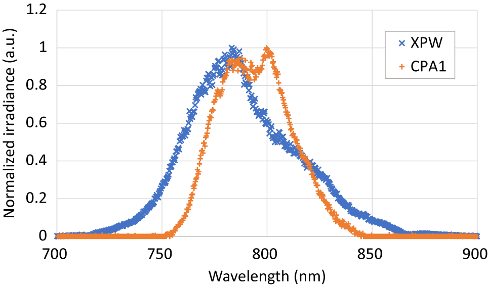
Figure 3 CPA1 and XPW spectra.
The XPW stage contributes to the enhancement of the femtosecond pulses intensity contrast with nearly four orders of magnitude, corresponding to the extinction ratio of input and output polarizers. After the XPW stage, a pulse selector/cleaner serves as a repetition rate reducer from 1 kHz down to 10 Hz, as well as a pulse cleaner for the nanosecond contrast enhancement. After this, the broadband 800 nm laser pulses, at 10 Hz repetition rate, propagate through a glass bulk stretcher, which stretches the pulse to about 15 ps. After passing through the pulse selector/cleaner and the bulk stretcher, the broadband seed pulse energy is reduced to the few microjoules level at the input of the ps-NOPCPA stage. To improve the intensity contrast and spectral bandwidth of the full system, a double ps-NOPCPA stage, with two BBO crystals, is used.
For the ps-NOPCPA pump pulse generation, a spectral part of the oscillator output pulses at 1064 nm (see Figure 2) is filtered through a band-pass mirror to get picojoule energy pulses with about 10 nm spectral bandwidth. These low-energy laser pulses are amplified and spectrally filtered in a two-stage fiber amplifier designed and manufactured by Venteon Company. The 1064 nm laser beam of ~1 mW average power from the oscillator is first coupled in an ytterbium-doped fiber amplifier to increase the average power to 150 mW, corresponding to nanojoule-level pulse energy. After spectral filtering in a fiber Bragg grating (FBG), the spectral bandwidth of the laser pulses is reduced to 0.066 nm. The pulse duration is shorter than 25 ps, near the Fourier transform limit (FTL) of the spectral bandwidth. After the spectral filtering, the average power of 1064 nm laser pulses is reduced to around 1 mW. A second ytterbium-doped fiber amplifier increases the average power of laser pulses up to 80 mW.
The nanojoule pulses of 25 ps duration from the fiber amplifier are seeded in a diode-pumped Nd:YAG regenerative amplifier running at 10 Hz repetition rate. This amplifier has been designed to be almost insensitive to optical misalignments and consists of a 2.5 m long resonant cavity using two corner cubes as highly reflective mirrors. This confers a long-term stability to the ps-NOPCPA picosecond pump pulses. The output regenerative amplifier laser pulses of 2 mJ energy are injected in a beam shaping device which consists of a quartz spherical lens combined with a polarizer. After the beam shaping, 1 mJ energy laser pulses, with a spatial intensity distribution converted from Gaussian to super-Gaussian profile, are generated (Figure 4).

Figure 4 Near-field spatial intensity profile of the picosecond pulses: (a) before beam shaping device; (b) after beam shaping device.
The millijoule energy picosecond pulses are launched in a double-pass flash-lamp pumped Nd:YAG amplifier. The output, amplified pulses of 150 mJ energy, are then frequency doubled in a potassium titanyl phosphate (KTP) crystal to generate the ps-NOPCPA pump pulses of ~80 mJ energy and less than 20 ps pulsewidth, at 10 Hz repetition rate, with a super-Gaussian beam intensity profile (Figure 5).

Figure 5 Near-field beam intensity profile of the 532 nm picosecond pump laser for OPCPA.
For optical synchronization of seed and pump pulses on the first of the two 12 mm × 12 mm × 4 mm BBO crystals, a delay line was installed on the seed beam. Both BBO crystals, pumped by 532 nm, 20 ps laser pulses, are cut for broadband amplification in a noncollinear geometry of the seed and pump wave vectors. The crystals are antireflection coated for pump and seed on both faces. The pump beam is split into two parts to pump both ps-NOPCPA stages. The pump beam from the second harmonic crystal output is relay imaged on the first BBO crystal with an energy of 16 mJ. It amplifies the seed from the few microjoules level to more than 1.5 mJ pulse energy.
The pump pulse for the second stage goes through a delay line that compensates for the propagation time between the two ps-NOPCPA stages and is then relay imaged to the second BBO crystal. It allows more than 10 mJ output pulse energy to be reached with a pump energy of 45 mJ. The evolution of the beam intensity spatial profile of the amplified broadband 800 nm laser pulse through the FE is shown in Figure 6.

Figure 6 Evolution of the 800 nm broadband beam spatial intensity profile through the FE. The FE near-field intensity and far-field intensity profiles were measured at the output of the second OPCPA stage.
The two-stage design of ps-NOPCPA allows a low enough gain to be maintained in each stage and any super-fluorescence to be prevented, which could degrade the picosecond contrast in the time domain of the pump. As no parametric gain is obtained outside the pump laser temporal window of ~20 ps, the intensity contrast in the ps-NOPCPA stages is enhanced by a value equivalent to the parametric gain[ Reference Chalus, Pellegrina, Ricaud, Casagrande, Derycke, Soujaeff, Rey, Radier, Matras, Boudjemaa, Simon-Boisson, Laux and Lureau 40 , Reference Mikhailova, Buck, Borot, Schmid, Sears, Tsakiris, Krausz and Veisz 41 ].
Because the two ps-NOPCPA stages can be managed by independent delay lines, it is possible to shape the spectrum of the final output for an optimum distribution for the subsequent Ti:sapphire amplification.
The main purpose of the FE is to deliver high spectrum stability broadband 800 nm laser pulses, re-compressible with very high temporal intensity contrast, for the subsequent Ti:sapphire high-energy amplifiers. By using optical synchronization of the seed and pump pulses, the electronic jitter is avoided, leading to a very stable and efficient parametric amplification. This is demonstrated through the stability of the output spectrum illustrated in Figure 7, where all spectra were acquired during 7 h continuous operation. A flattened spectrum, spreading through about 100 nm bandwidth, has been obtained at the ps-NOPCPA output (see Figure 7).

Figure 7 Stability of the OPCPA spectrum over 7 h continuous operation. The red curve is the average of the data acquired at 10 min intervals that we represented by the gray curves.
The contrast of the FE was qualified using a procedure based on the measurement of the individual contributions to the overall temporal contrast of the different amplification stages in the FE. A third-order cross-correlator (Tundra from Ultrafast Innovation[ 42 ]), having an 11 orders of magnitude dynamic range, was used to perform the temporal contrast measurements. The results are depicted in Figure 8.
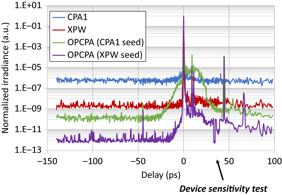
Figure 8 FE contrast assessment. By blocking the device input, the limitation of the measurement device sensitivity has been evaluated in the range of 10–13.
For these tests, a test compressor based on prisms was used in front of the third-order cross-correlator to compress the pulses to about 30 fs at FWHM. The contrast of the first Ti:sapphire amplifier (CPA1), before the XPW, is depicted with the blue line in Figure 8. A contrast better than six orders of magnitude has been measured. The intensity contrast measured for the XPW, depicted with the red line, is limited in its dynamic range due to the low energy at the output (30 μJ). Enhancement of nearly three orders of magnitude can be estimated.
The contrast measurement of the entire FE system (the purple curve in Figure 8) shows a clear limitation owing to the dynamic range of the measurement tool. Before –40 ps, the overall contrast of compressed FE output pulses (CPA1+XPW+OPCPA, see the purple curve in Figure 8) cannot be measured because the signal is out of the dynamic range of the instrument. Without the XPW (CPA1+OPCPA, see the green curve in Figure 8), we measured at –40 ps a value of the order of 10–10 intensity contrast, which is within the detection range of the instrument. Comparing blue and green curves in Figure 8, we can extrapolate that the contrast enhancement of the ps-NOPCPA outside of the pump gain is better than three orders of magnitude. To estimate the overall contrast, this value was divided by the measured contrast improvement of the XPW. As a consequence, a value in the range of 10–13 actual intensity contrast of the full FE, at –40 ps before the main femtosecond pulse, has been evaluated. The measurements indicate no contrast degradation on an extended range beyond –40 ps.
2.2 The power amplifiers
The 10 mJ pulses produced by the FE are split into two pulses with equal energy. Each 5 mJ pulse is then stretched to seed the first amplifier system on each arm (AMP1 in Figure 1). This amplifier has two multi-pass Ti:sapphire stages (AMP1.1. and AMP1.2.), five passes each, pumped by eight high-energy flashlamp-pumped frequency-doubled Nd:YAG lasers (SAGA HP manufactured by Thales[ 43 ]). Each SAGA HP pump laser delivers up to 1.8 J at 10 Hz, with a pulse-to-pulse energy stability better than 1.2% root mean squared (RMS) and a uniform near-field beam profile as shown in Figure 9. A small part, less than 200 mJ, of the pulse energy of one SAGA HP laser is available for pumping the Ti:sapphire crystal of the AMP1.1 stage.

Figure 9 The typical beam profile of the pump lasers.
The second amplification stage (AMP2 in Figure 1), corresponding to the 1 PW level amplifier, is a three-pass Ti:sapphire amplifier pumped by six high-energy flashlamp-pumped frequency-doubled Nd:YAG lasers (GAÏA HP manufactured by Thales[ 44 ]). A GAÏA HP pump laser delivers 16 J energy in two pulses lasting 15 ns FWHM each at 532 nm, at 1 Hz repetition rate, with a pulse-to-pulse energy stability better than 1.2% RMS.
As shown in Figure 1, the third amplifier stage (AMP3), for the 10 PW beams, has two Ti:sapphire crystals in multi-pass configuration (AMP3.1. and AMP3.2), pumped by eight high-energy flashlamp-pumped frequency-doubled Nd: glass lasers (ATLAS 100 manufactured by Thales[ 31 ]). An ATLAS 100 laser delivers up to 100 J energy in two pulses, of ~20 ns FWHM pulsewidth each (see Figure 10) at 527 nm, at 1 shot/min, with a pulse-to-pulse energy stability better than 1.5% RMS. AMP3.1 is a three-pass amplifier using a 130 mm diameter Ti:sapphire crystal pumped by two ATLAS 100 lasers. AMP3.2 is also a three-pass amplifier using a 200 mm diameter Ti:sapphire crystal pumped by six ATLAS 100 lasers. GT Advanced Technologies (USA) supplied all the Ti:sapphire crystals. Table 1 summarizes the energy management and beam size for the 10 PW amplification mode.

Figure 10 Pulse temporal profile of the ATLAS 100 laser, 50 ns/div; delay between laser pulses was set at 50 ns; the entire FWHM pulse duration, for combined pulses, is about 70 ns.
Table 1 Main beam parameters at each amplification level during the 10 PW operation.

All high-energy amplifiers were designed with similar pump fluence on the Ti:sapphire crystal’s faces, limited to a safe value of 2 J/cm2. By overlapping the pump laser beams, a quasi-uniform spatial pump intensity profile was obtained and the output of each amplifier shows a homogenous, nearly flat profile as illustrated in Figure 11.

Figure 11 The beam profile at the output of each main amplifier.
A critical aspect for the overall laser performance is the management of transverse lasing effects and amplified spontaneous emission (ASE). The HPLS Ti:sapphire crystals mounts use a cooling liquid with refractive index matched with the refractive index of the Ti:sapphire crystal, with a fluorescence absorbing dye, in order to prevent the transverse lasing[ Reference Laux, Lureau, Radier, Chalus, Caradec, Casagrande, Pourtal, Simon-Boisson, Soyer and Lebarny 45 ]. At a certain pumping level, especially for the large-diameter Ti:sapphire crystals of AMP3.2, this technique is no longer sufficient. In this case, the timing of pump energy deposition versus incoming seed pulse becomes crucial. Following a Thales patent[ Reference Marquis 46 ], in the final three-pass amplifier, 50% of the available pump energy is deposited before the seed pulse arrival, whereas 25% is deposited between the first and second passes, and the rest of the pumping energy is deposited before the last pass. Owing to energy extraction between laser pulse passes, this technique allows the transversal gain on the crystal to be kept low enough to prevent the transversal lasing. Nevertheless, the laser pulse gain remains high enough to reach saturation and to efficiently extract the energy deposited in the Ti:sapphire crystal.
2.3 Stretchers–compressors/dispersion and spectral control
A schematic configuration of the high-energy Ti:sapphire amplification is shown in Figure 12, together with the Offner stretcher after the FE, and the compressors, specifying the pulse durations at the entrance in the compressors. To run AMP3.1 and AMP3.2 safely, the intensity at the last amplifier output should remain below 2.7 GW/cm2, to have sufficient margins before reaching the laser damage threshold. As a consequence, the stretched pulse duration has to be at least 900 ps for full amplification. Hence, the stretched pulse after the Offner stretcher is 900 ps as indicated in Figure 12. The stretcher has a dual-grating Offner design[ Reference Jiang, Zhang and Hasama 47 ] that uses 1480 lines/mm gratings at a relative distance of 486 mm and an incidence angle on the first of 56°.
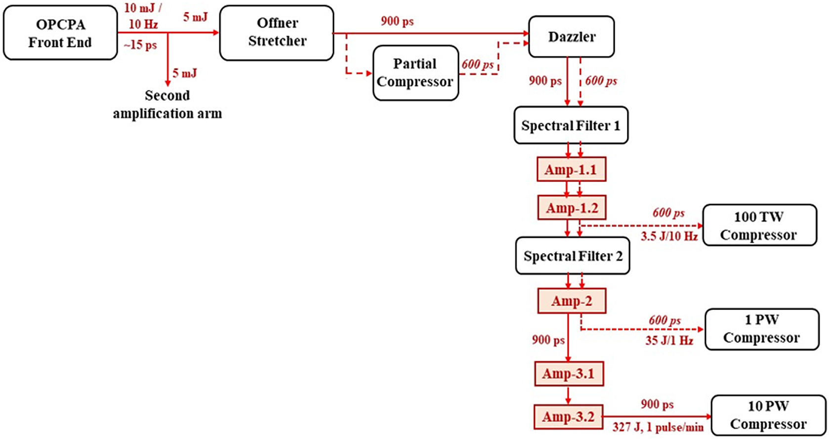
Figure 12 Schematic configuration of the high-energy Ti:sapphire amplification arm.
For the other amplification stages (AMP1.1, AMP1.2, AMP2) and at the input of the 100 TW and 1 PW compressors, the pulse duration can be shorter, namely 600 ps, without risking to damage the optical components. A partial compressor, implemented just after the 10 PW Offner stretcher, is used to reduce the 900 ps pulse duration to the 600 ps pulse duration required by the 100 TW and 1 PW compressors when these outputs are active. This partial compressor is working in a dual-grating Treacy configuration, using 1480 lines/mm gratings at 56° angle of incidence, with a grating distance of 307 mm along the 800 nm wavelength path. The partial compressor is only switched in when using the 100 TW and 1 PW laser beam lines. It is bypassed when working on the 10 PW beam line. The partial compressor gratings have the same characteristics as the 10 PW compressor gratings, but with a distance between gratings reduced by a factor of a third. Reducing the output stretched pulse duration enables the distance between 100 TW and 1 PW compressor gratings to be shortened, minimizing the required size of the second and third gratings and the size of the vacuum chambers for these compressors.
The 100 TW and 1 PW compressors were optimized to have a compression rate of ~10 ps/nm for an input pulse of about 600 ps duration having a spectral aperture of 170 nm centered at 800 nm. The 10 PW compressor has a compression rate of ~13.6 ps/nm and it accommodates the 900 ps pulses having a spectral aperture of 170 nm centered at 800 nm. All three types of compressors work in the standard Treacy configuration[ Reference Treacy 38 ]. The 100 TW compressor uses two gratings in a double-pass configuration, whereas the 1 PW and 10 PW compressors use four gratings in a single-pass configuration. All gratings have 1480 lines/mm at 56° angle of incidence. The FWHM beam size at the compressor input is 55 mm for the 100 TW, 160 mm for the 1 PW, and 450 mm for the 10 PW compressors. The distance between the first and second gratings along the 800 nm wavelength path is 717 mm for the 100 TW and 1 PW compressors, and 973 mm for the 10 PW compressors, corresponding to the two compression rates mentioned previously. The 10 PW compressor, a key component of the HPLS, is using meter size, ~575 mm × 1015 mm, gold-coated, broadband optical gratings provided by Horiba France (see Figure 16 in Section 3).
An acousto-optic programmable dispersive filter[ Reference Tournois 48 ] (Dazzler produced by Fastlite) was implemented after the partial compressor to compensate for the high-order dispersion. The Dazzler is working in conjunction with spectral phase measurement devices based on self-reference spectral interferometry[ Reference Oksenhendler, Coudreau, Forget, Crozatier, Grabielle, Herzog, Gobert and Kaplan 49 ] (Wizzler produced by Fastlite) placed on the diagnostic benches, after each of the output compressors. These feedback loops pre-compensate for the different high-order phase distortions to achieve a flat spectral phase at each output of the laser. A bulk compensator was introduced between the Offner stretcher and the Dazzler to compensate for higher-order material dispersion. The bulk compensator is designed to introduce a group delay dispersion of –2.85 × 10⁵ fs2, a third-order dispersion of –6.83 × 10⁴ fs3, and a fourth-order dispersion of –8.15 × 10⁵ fs4.
The spectral bandwidth after amplification was managed using spectral filter mirrors[ Reference Giambruno, Radier, Rey and Chériaux 14 ] installed at the entrance of AMP1.1 and AMP2, as shown in Figure 12. These filters, with the typical reflectivity and second-order dispersion presented in Figure 13(a), are designed to pre-compensate for the spectral gain narrowing and red shifting by attenuating the central spectral components. The spectral mirrors are used in pairs, and the central wavelength of the hole is tuned by modifying the angle of incidence.

Figure 13 Spectral bandwidth management through the high-energy Ti:sapphire amplifiers: (a) typical reflectivity and dispersion of the spectral filters at 45° angle of incidence; (b) simulation of 100 μJ energy, Gaussian spectrum seed pulse (blue line) propagation through five chirped pulse amplifiers to reach 90 J output pulse energy, with spectral shaping mirrors (gray line) and without spectral shaping mirrors (red line).
In Figure 13(b), we illustrate the effect of the spectral filtering mirrors. The propagation of a chirped seed pulse of 100 μJ energy is simulated, with Gaussian distribution of the spectrum centered at 800 nm (blue curve), through five chirped pulse amplifiers in order to achieve around 90 J, equivalent to a potentially 3 PW laser system. If no spectral management is performed in between the amplifiers, the final spectrum is centered at 832 nm and presents only 36 nm FWHM of bandwidth (red curve). However, if two sets of spectral shaping management mirrors are introduced in between some amplifiers, the output spectrum that can be extracted is centered at 823 nm, with a bandwidth of 69 nm FWHM (gray curve).
The evolution of the chirped pulse spectrum, measured through the high-power Ti:sapphire amplifiers, with two spectral shaping mirrors before AMP1.1 and AMP2, is presented in Figure 14.

Figure 14 Evolution of the spectrum through the high-power Ti:sapphire amplifiers
2.4 Beam interfaces and diagnostics
To avoid technical difficulties arising from vacuum requirements associated with Kepler-type telescopes, Galileo-type mirror telescopes from Optical Surfaces Ltd.[ 50 ] were used to expand the beams before compressors (Figure 15).

Figure 15 The HPLS 10 PW compressor and diagnostics diagram; the inset is a picture of one of the two ELI-NP 10 PW compressors using the meter size gratings. D.M., deformable mirror; WFS, wavefront sensor; CCD-NF, near-field CCD; CCD-FF, far-field CCD; AUTO-CO, single-shot autocorrelator; CROSS-CO, third-order cross-correlator.
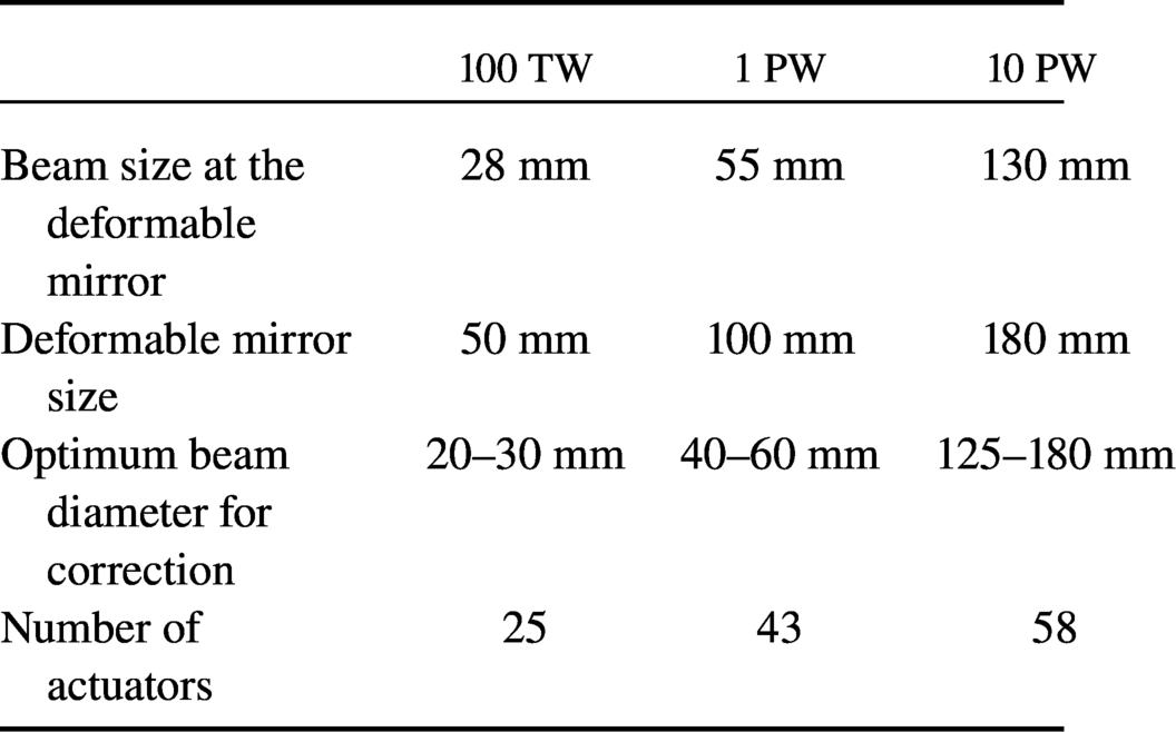
Deformable mirrors were integrated for each HPLS output, before the last beam expander (see Figure 15), to correct for the wavefront distortions accumulated during the beam propagation through the amplification system. They are operated in a closed loop with wavefront sensors integrated into the diagnostic benches (Figure 15). These wavefront control loops provided by Imagine Optic are composed by mechanically actuated deformable mirrors (from the ILAO Star family[ 51 ]) and a Shack–Hartman wavefront sensor (HASO 4 First[ 52 ]) integrated in the diagnostic bench and described in the following paragraphs. The deformable mirror sizes, number of their actuators, correction aperture size, and actual beam size are summarized in Table 2.
Table 2 Beam size and deformable mirror characteristics.
In each compressor, one of the mirrors used to steer the beam out is a specially designed leaky mirror (produced by Okamoto Optics), with a flat spectral transmission. This mirror, with ~99.5% reflectivity and ~0.4% transmission, is used to sample the full aperture beam for the on-shot diagnostics. The transmitted beam is sent on the diagnostic bench for different measurements.
On the diagnostic bench, the beam is reduced in size using the same type of telescope as at the entrance of the compressors to keep the beam distortions at a minimum. Then, the beam is further reduced in size using additional sets of pairs of concave/convex mirrors to a collimated 4 mm diameter in free propagation. This beam is then sampled towards the different equipment on the diagnostic bench.
For the wavefront sensor, a set of two plano-convex lenses allows relay imaging of the beam to be performed. The position of the wavefront sensor is then carefully chosen after the second lens to be in the image plane of the deformable mirror. This ensures proper calibration and control of the entire loop. Calibration of the wavefront sensor measurement was performed using a flat etalon mirror to extract any residual aberrations of the diagnostic bench. Two CCDs are used to monitor the near-field and far-field spatial profiles of the compressor output beam.
The Wizzler self-referenced spectral interferometer was used for pulse duration and spectral phase measurement. A single-shot autocorrelator helps to tune the system to achieve a pulse duration of about twice its FTL, in the range where the Wizzler can perform the pulse measurements. As described previously, the Wizzler–Dazzler loop is used in order to correct the spectral phase and achieve the short pulse duration. A third-order cross-correlator (Tundra from Ultrafast Innovation) was used for pulse contrast measurements.
Energy and spectrum are monitored on the diagnostic bench using calibrated energymeters and spectrometers, respectively.
Using these diagnostic benches, all the six outputs of the HPLS were qualified and the results are summarized in Table 3.
Table 3 Measured parameters of the HPLS.
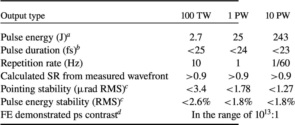
Notes: a Calculated considering the transmission efficiency of temporal compressors (see the procedure described in Section 3).
b Measured with attenuated input energy in the compressors (see the procedure described in Section 3).
c The numbers of pulses used for the stability measurements for the amplifiers are: 100 TW, 1000 shots; 1 PW, 1000 shots; 10 PW, 100 shots.
d Indirectly measured by the method described in Section 2.1.
Laser-driven experiments with capillaries, limited mass targets, or combined focused beams, as proposed for ELI-NP[ Reference Gales, Tanaka, Balabanski, Negoita, Stutman, Tesileanu, Ur, Ursescu, Andrei, Ataman, Cernaianu, D'Alessi, Dancus, Diaconescu, Djourelov, Filipescu, Ghenuche, Ghita, Matei, Seto, Zeng and Zamfir 33 , Reference Tanaka, Spohr, Balabanski, Balascuta, Capponi, Cernaianu, Cuciuc, Cucoanes, Dancus, Dhal, Diaconescu, Doria, Ghenuche, Ghita, Kisyov, Nastasa, Ong, Rotaru, Sangwan, Söderström, Stutman, Suliman, Tesileanu, Tudor, Tsoneva, Ur, Ursescu and Zamfir 34 ], require good pointing stability. This is addressed by decoupling from vibrations the entire platform that supports the HPLS, the beam transport system, and the interaction vacuum chambers. This large concrete anti-vibration platform rests on spring and dampers. On this platform, all the optics, including the HPLS, are connected using stable mechanical mounts.
To compensate for the long-term beam pointing drifts, three feedback loop beam pointing systems, based on motorized mirrors, near-field and far-field cameras, were implemented before XPW stage, before the ps-NOPCPA stage 1, and before the AMP1, respectively.
The pointing stability reported in Table 2 has been achieved by combining these technical solutions. The pointing stability was measured using the wavefront sensor on the diagnostic bench. The tilt on the two orthogonal axes is extracted from the coefficients in the Zernike decomposition of the measured wavefront. The duration of the measurement depends on the output and is 1000 shots for 100 TW output, 1000 shots for 1 PW output, and 100 shots for 10 PW output. A low aberration beam wavefront is of crucial importance for the focused pulse spot size, and hence the achievable peak irradiance. All optics were specified to be of a very high optical quality and were carefully chosen with the manufacturer. Wavefront errors of every large optics were characterized and they were assembled in such a way as to minimize their overall effect on the wavefront of the laser beam.
3 10 PW output results
In the 10 PW configuration, to better manage the spectral bandwidth and accumulated nonlinearities over the entire system, some of the early amplifiers were run at lower energy. Reducing the pumping energy, only 20 J out of the available 36 J from amplification stage AMP2 was used to seed the third amplification stage. The energy per pulse of about 327 J has been reached, with a spectral bandwidth larger than 70 nm FWHM, using only 80 J pump pulse energy from each ATLAS 100 laser. Each of ATLAS 100 pump laser delivers up to 100 J per pulse[ Reference Lureau, Laux, Casagrande, Chalus, Pellegrina, Matras, Radier, Rey, Ricaud, Jougla, Charbonneau, Duvochelle and Simon-Boisson 53 ]. The pulse energy was decreased to about 80 J, enough to achieve the reported level of amplification, by limiting the voltage applied on flashlamps and therefore increasing their lifetime.
Figure 16 shows the extraction efficiency of the last amplifier (AMP3.2) seeded with about 90 J by AMP3.1. A saturation at about 47% extraction efficiency and an output energy of 327 J were obtained with a total pump energy of 480 J.
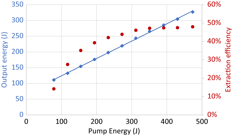
Figure 16 Extraction efficiency for the 10 PW level amplifier AMP3.2.
The setup for measurement of the output parameters for the femtosecond 10 PW pulses is described in Figure 15. Owing to the lack of a beam dump for the full-energy femtosecond pulses, for the characterization of the 10 PW pulses, one mirror of the periscope in front of the compressor has been replaced with a 1.4% reflectivity wedge. At this reduced fluence, the beam can be dumped on the output flange of the compressor. Using this strategy, one can use the fully amplified and full aperture beam for all the measurements.
The energy of the fully amplified beam is measured through the leakage of the periscope mirror using a calibrated energymeter. The energymeter and the sampling system (leaky mirror and demagnification optics) are calibrated against fully amplified energy at the entrance in the compressor. Before the beam expander of the compressor, directly into the main beam path, a relatively low-energy beam (~30 J) was sent through a 200 mm diameter lens in order to reduce its size from 130 mm to about 80 mm, the size of the used calibrated energymeter (QE95 from Gentec). The first set of measurement was performed in this setup. The lens system and the energymeter were then moved on the sampled beam used for the measurements. A second set of measurements was performed and the calibration factor was calculated. The calibration is done using average values over 100 shots. It has been also checked that the sampling efficiency does not depend on the spectrum. All the other measurements were performed using the diagnostic bench.
The output pulse duration was optimized by an iterative process using Wizzler and Dazzler. In Figure 17(a), one can see the flat spectral phase obtained after the Dazzler optimization and the large spectral bandwidth of the pulse, of more than 70 nm. In Figure 17(b), it is represented that the Wizzler reconstructed pulse temporal shape has a duration of about 22.7 fs at FWHM. This pulse duration value is in good agreement with the FTL pulse duration calculated for the measured spectrum.

Figure 17 Wizzler measurements: (a) flat spectral phase and more than 70 nm spectral bandwidth; (b) reconstructed pulse with τ = 22.7 FWHM duration.
The compressor efficiency was calculated based on the measurement performed on each grating in the factory using an efficiency meter on 19 points at 785 nm test wavelength. These 19 measurement points are distributed on the surface of each grating, covering the entire clear aperture of it. Efficiency higher than 88.5% was measured for each point on all the gratings. A minimum average efficiency for one grating of 90.5% and a maximum of 94% for the best were calculated. For the compressor used in this experiment, overall efficiency of 74.2% has been calculated by multiplying the average value of each compressor grating efficiency. The diffraction efficiency of the used gratings is flat above 90% for the spectral range 730–900 nm. The measured spectrum at the output of the compressor is not significantly modified in comparison with the spectrum at the input of the compressor.
The peak power, Pp , of femtosecond laser pulses has been estimated[ Reference Wang, Liu, Shen, Zhang, Teng and Wei 7 , Reference Chu, Liang, Yu, Xu, Xu, Ma, Lu, Liu, Leng, Li and Xu 8 , Reference Sung, Lee, Yoo, Yoon, Lee, Yang, Son, Jang, Lee and Nam 10 , Reference Zeng, Zhou, Zuo, Zhu, Su, Wang, Wang, Huang, Jiang, Jiang, Guo, Xie, Zhou, Wu, Mu, Peng and Jing 12 , Reference Kiriyama, Pirozhkov, Nishiuchi, Fukada, Ogura, Sagisaka, Miyasaka, Mori, Sakaki, Dover, Kondo, Koga, Esirkepov, Kando and Kondo 13 ] using a simplified equation, Pp = ηE/τ, where E is the compressor input pulse energy, η is the compressor efficiency, and τ is the FWHM femtosecond pulse duration. Considering the compressor input pulse energy reported in Figure 16, E = 327 J, the compressor efficiency, η = 0.742, the reconstructed FWHM pulse duration from Figure 17(b), τ = 22.7 fs, and using this equation, we estimated in the same way a peak power of 10.68 PW. By numerical integration of the power temporal profile of the femtosecond laser pulse, reconstructed in Figure 17(b), we calculated that 87% of the total energy is carried in the main pulse. Considering the same compressor input pulse energy of 327 J and 0.742 compressor efficiency, we numerically calculated a more accurate value of 9.34 PW peak power corresponding to the full-energy femtosecond laser pulses.
In Figure 18, an assessment of the contrast at the output of the laser system is presented. One can observe that the contrast curves at 100 TW, 1 PW, and 10 PW follow the same trend, going beyond the limit of the recording device. Owing to the repetition rate of 1 shot/min, the number of experimental points for the 10 PW temporal contrast curve is smaller than in the other two cases. This leads to uncertainty in the normalization value (pulse peak). It can be noticed when comparing Figures 8 and 18 that a pedestal rose from 130 ps to the main pulse. This pedestal is attributed to the stretcher[ Reference Dorrer and Bromage 54 , Reference Ranc, Le Blanc, Lebas, Mathieu, Radier, Martin, Ricaud, Zou, Druon and Papadopoulos 55 ]. Work is in progress to improve the contrast.
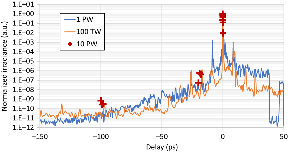
Figure 18 Contrast measurements at the output of the HPLS for the different amplification levels.
A uniform beam profile (as shown in Figure 10, AMP3) was obtained, following the profile of the ATLAS 100 pump lasers. The wavefront distortions are compensated using the deformable mirror in a closed loop with the wavefront sensor on the diagnostic bench as described previously. Figure 19 shows the 50 nm RMS and 334 nm PV residual wavefront distortion as well as an SR of 0.9 (calculated using the wavefront sensor software and the measured irradiance profile). The far-field camera measurement confirmed the beam quality on the diagnostic bench (as shown in Figure 19). The wavefront sensor was used for the qualification of the beam pointing stability, shown to be below 1.27 μrad RMS and 5.5 μrad peak to peak for the 10 PW HPLS outputs (see Table 3).

Figure 19 Measured data from the wavefront sensor and far-field camera on the 10 PW diagnostic bench. The wavefront map shows a wavefront error of 0.05 μm RMS. The calculated PSF from the measured irradiance map and wavefront map shows an SR of 0.9. Far-field profile confirms the good focusability of the beam.
Laser stability measurement was performed using 300 J energy before compression. The average energy measured for 90 consecutive shots was 300 J, with a stability of 1.8% RMS (Table 4). The low value of the minimum is due to a misfire of one of the pump lasers for only one shot during the 90 min measurement time.
Table 4 Stability test for the 10 PW level amplifier running for 90 min at 300 J.

An up-time per day of over 8 h at the 1 PW output running at 1 Hz at the amplified energy of 38 J before compression is shown in Figure 20, as a further demonstration of the reliability of the HPLS. This corresponds to over 25,000 shots per day. The reduced energy levels depicted in green and yellow are due to the pump laser crash test (pump lasers were stopped for a limited time) in AMP2 and AMP1, showing the fast recovery time of the laser system.

Figure 20 Long-term stability test for the 1 PW level amplifier during 1 day of operation showing the energy of all the shots before compression.
4 Conclusions
We have described in this paper a two-arm hybrid high-power femtosecond laser system, with both arms seeded from a common FE, having the capability to deliver 2 × 10 PW peak power femtosecond pulses.
The measured 327 J chirped pulse energy at the output of the final high-energy amplifier, corroborated with the 74.2% transmission efficiency of the 10 PW temporal compressor and the 22.7 fs pulse duration, measured at an attenuated pulse energy, demonstrates that the described high energy femtosecond laser system can deliver 10 PW laser pulses in each of the two amplification arms.
The system is designed starting from the requirements of a user facility, and the redundant FE and the additional available pumping energy are providing the required margins for a high beam availability for the users. In addition, the spatial wavefront and spectral phase control by using the deformable mirrors and Dazzler provides tools for ensuring flexibility in the achievement of the user required beam parameters in the focal region.
The reported repetition rate, pointing, and energy stability demonstrate the reliability of the laser system. The repetition rate of one shot per minute is the highest reported for a 10 PW laser system, to the best of the authors’ knowledge. The beam pointing stability below 1.7 μrad RMS at the 10 PW outputs is expecting to make possible shooting in capillaries and mass-limited targets in the coming nuclear physics and related experiments[ Reference Gales, Tanaka, Balabanski, Negoita, Stutman, Tesileanu, Ur, Ursescu, Andrei, Ataman, Cernaianu, D'Alessi, Dancus, Diaconescu, Djourelov, Filipescu, Ghenuche, Ghita, Matei, Seto, Zeng and Zamfir 33 , Reference Tanaka, Spohr, Balabanski, Balascuta, Capponi, Cernaianu, Cuciuc, Cucoanes, Dancus, Dhal, Diaconescu, Doria, Ghenuche, Ghita, Kisyov, Nastasa, Ong, Rotaru, Sangwan, Söderström, Stutman, Suliman, Tesileanu, Tudor, Tsoneva, Ur, Ursescu and Zamfir 34 ].
Based on the seeding of the two high-energy amplification arms from a common FE, future experiments of 2 × 10 PW femtosecond laser pulses synchronization could be performed.
Currently, the 10 PW Laser Beam Transport System (LBTS) is under test and a full-power 10 PW endurance test of the entire system is ongoing. During this test we are assessing a complete set of parameters such as the wavefront and near-field irradiance profile. The test results, when ready, will be the subject of a follow-up paper that will concentrate on the parameters of the beam delivered for the users.
The reported results represent a milestone in the implementation of a fully functional 2 × 10 PW femtosecond laser-driven nuclear physics facility at the Bucharest-Magurele Extreme Light Infrastructure Nuclear Physics.
Acknowledgments
Extreme Light Infrastructure Nuclear Physics (ELI-NP) Phase II, is a project co-financed by the Romanian Government and the European Union through the European Regional Development Fund and the Competitiveness Operational Programme (1/07.07.2016, COP, ID 1334). We gratefully acknowledge the contribution of the entire Thales and ELI-NP teams and collaborators.


 Open access