Scanning electron microscopy (SEM) is a versatile tool to reveal the microstructures inside objects. To better observe these contents, cross sections of the specimen are often produced. When a cross section is needed, damage prevention can be particularly challenging. Cross sections may be prepared simply, for example by cutting with a razor blade or scissors. This method is easy and economical, but it can introduce significant artifacts by crushing the structure or leaving noticeable tool marks on the prepared edge. More complex preparation methods (for example, freeze-fracture, microtomy, mechanical polishing) can be difficult, unpredictable, time-consuming, and expensive—even then the face of the cross section may not be clean and damage-free, particularly with easily deformable materials or mixed hard-and-soft materials.
Argon-beam polishers have been available commercially for at least a decade [Reference Erdman1] from several manufacturers including JEOL Ltd., Gatan Inc., Hitachi High-Technologies Corp., and Fischione Instruments, Inc. By using a broad unfocused beam of argon ions, these devices create a highly polished cross section with minimal distortion [Reference Erdman2]. This polishing technique does have some drawbacks, including limitations on sample size, sample heating in the argon beam, and difficulty holding or orienting materials such as fine powders, irregularly shaped items, and small wires. This article describes a method to help resolve the latter problem.
Materials and Methods
As the physical composition of particulates may vary, it can be difficult to cleanly cut materials to examine their internal features. Below is a general procedure for preparing and polishing cross-section specimens of particulates and wires.
Materials
1. Two-part epoxy such as Devcon 5 minute epoxy gel (ITW Devcon, Danvers, Massachusetts, USA). This epoxy does not require heating and is transparent on curing, so the embedded sample remains visible, which is not the case with some epoxies (for example, Gatan G1 epoxy cures opaque and almost black in 10 minutes at 130°C).
2. Polytetrafluoroethylene (PTFE; Teflon) sheet (JEOL USA, Peabody, Massachusetts or other supplier).
3. Aclar fluoropolymer film (Ted Pella, Inc., Redding, California USA).
Procedure
1. Dispense equal amounts of the two epoxy components on a disposable surface like cardboard (Figure 1A). Mix gently but thoroughly with a disposable tool such as a toothpick or wooden applicator stick (Figure 1B). Avoid introducing air bubbles.
2. Transfer some of the epoxy to the PTFE sheet, and form a rectangular puddle about 20 mm × 10 mm × 3 mm deep. Work quickly so the epoxy does not begin to set.
3. Place a generous amount of the powder on top of the epoxy; do not mix (Figure 1C). The powder should be concentrated in one area rather than dispersed.
4. Cover the epoxy/powder surface with a piece of Aclar (Figure 1D), which will remain attached to the sample permanently. The Aclar should be larger than the area covered by the powder. Press down gently on the Aclar to thin the epoxy puddle to about 1–1.5 mm thickness, and submerge the powder (Figure 1E). The powder grains will spread apart somewhat; the goal is to have just enough epoxy between the grains to hold them in place.
5. Allow the composite to cure, which may take longer than stated on the epoxy label.
6. Remove the firm epoxy wafer containing the powder by flexing the PTFE sheet slightly (Figure 1F).
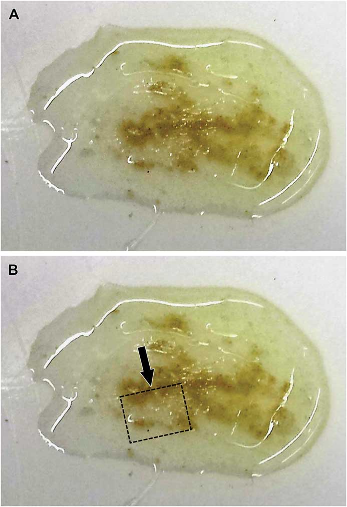
7. Using a stereomicroscope with transmitted light to inspect the sample (Figure 2A), choose and mark an area where the powder is concentrated. The aim is to have many powder grains along the edge that will be polished.
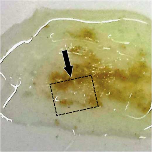
8. With a razor blade, cut the epoxy wafer and overlying Aclar into an appropriate size and shape for the argon-beam polisher, making the edge to be polished perpendicular to the surface (face of cut surface marked by arrow in Figure 2B).
9. For thermally sensitive samples, a gold coating can be applied to both sides of the sample using a sputter coater to help dissipate heat. If the gold coating is not too thick, the powder grains will still be visible for easy alignment in the polisher.
10. Place the sample in the polisher so that the Aclar film is on the side closest to the argon-beam source; polish through the Aclar first, then the powder-containing epoxy. Align features of interest (that is, the concentrated powder grains) in the center of the beam.
11. Once the polishing cycle is complete, check the polished edge with the stereomicroscope to assure that the polish has proceeded to the appropriate depth and the desired number of powder grains have been polished. Multiple polishes can be made along the same cut edge.
12. Because the epoxy is nonconductive, additional gold or carbon coating of the polished edge may be needed to control charging during SEM imaging.
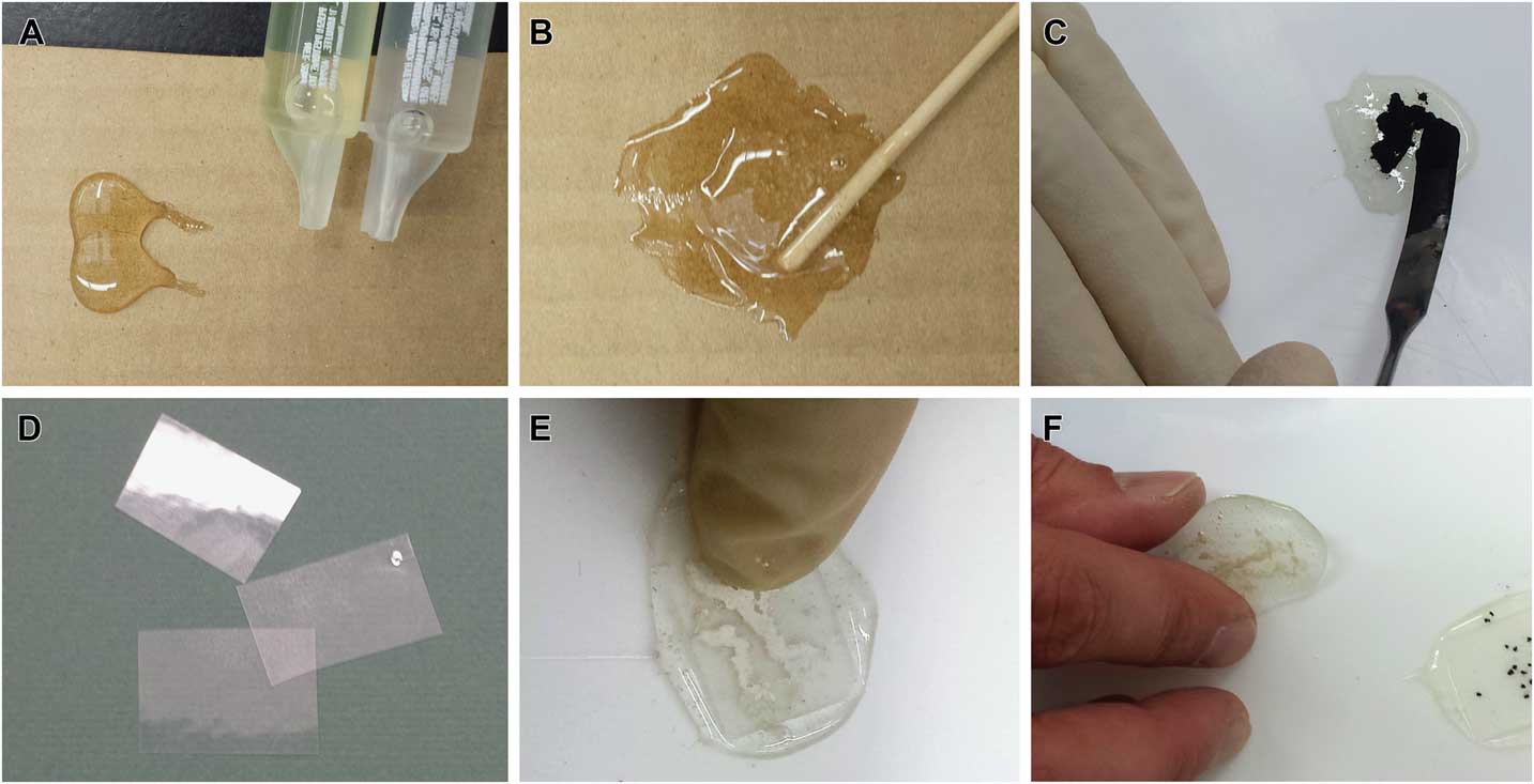
Figure 1 Stepwise procedure for embedding a powdered substance in two-part epoxy for cross-sectional polishing. (A) Dispense epoxy components onto cardboard. (B) Mix thoroughly. (C) Apply powder to surface of epoxy on PTFE sheet. (D) Cut Aclar® to use as a cover. (E) Press Aclar® gently into epoxy. (F) Remove cured epoxy containing powder sample.

Figure 2 Powder embedded in epoxy. (A) Surface of cured epoxy containing the powder. (B) Outline for trimming epoxy/powder block. Edge to be polished (arrow) traverses an area of high powder concentration.
Procedure for embedding wires
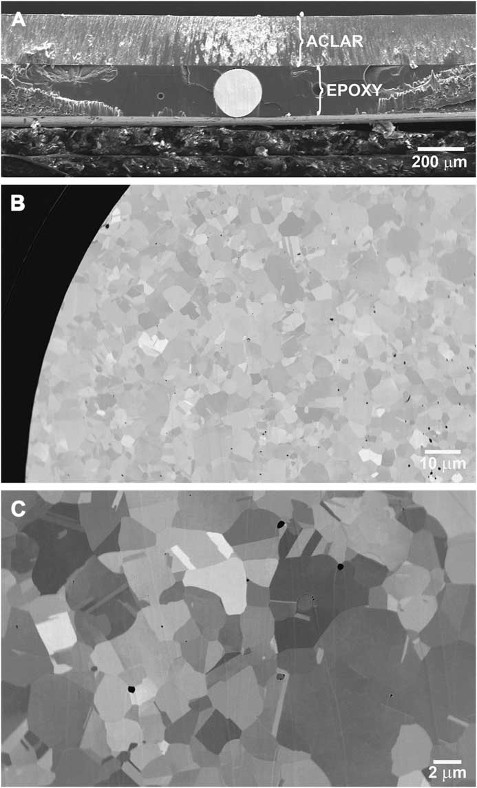
Position the wire in the liquid epoxy and press the Aclar film down to the surface of the wire (Figure 3A); allow the mixture to cure. Cut through the hardened epoxy and the wire with a razor blade, scissors, or wire cutters, depending on the diameter and hardness of the wire. Because the epoxy layer is very thin at the top and bottom of the wire, the wire may detach from the epoxy; if it does, recut in another area. Polish the cut end of the wire.

Figure 3 Embedded and polished coated copper wire. (A) The Aclar® covering has been pushed down to the surface of the wire during embedding. (B, C) Scanning electron micrographs of polished wire cross section; metallic grain structure is obvious.
Procedure for embedding larger irregular single particles
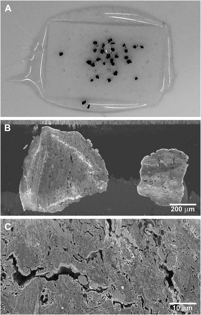
Press down the Aclar film epoxy to the surface of the particle. When trimming, cut through the particle if possible to expose some of the interior for polishing. After trimming, the edge of the epoxy wafer can be shaved with a razor blade to expose more of the interior area of interest. Polish the exposed particle (Figures 4 and 5).
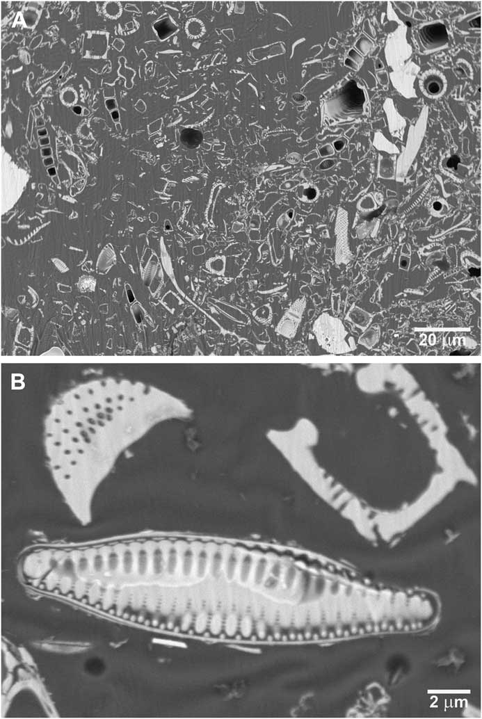
Figure 4 Embedded powder of diatomaceous earth. Low (A) and high (B) magnification SEM micrographs of polished cross sections containing many diatoms.

Figure 5 Embedded (A) iron-impregnated carbon particles. (B, C) SEM micrographs of polished cross sections.
Micrographs were taken using either a JEOL JSM-6490LV variable-pressure SEM or a JEOL JSM-7600F field-emission SEM (JEOL USA, Peabody, Massachusetts).
Results
High-quality SEM images can be obtained from samples embedded in commercial epoxy and polished with an argon-beam cross-sectional polisher. Wire cross sections of copper alloys, like most metals, exhibit polycrystalline grain structure, and grain size is readily discernable after polishing (Figure 3). Polishing a powder results in smooth cross sections of many powder particles (for example, diatomaceous earth, Figure 4). Epoxy embedding holds larger particles firmly for polishing. The iron-impregnated carbon particles illustrated in Figure 5 are extremely hard and difficult to hold. Other methods to view the interior structure had been unsuccessful.
Discussion
The transparent epoxy holds the sample material firmly, and accurate alignment is simplified so that the structures to be polished can be selected with precision. Pressing down the liquid epoxy makes the final preparation thin, eliminating the need for prolonged polishing to an excessive depth in order to reach the object(s). The pressing also concentrates as many powder grains as possible in the smallest possible amount of matrix. Argon-beam cross-section polishing does not introduce artifacts such as smearing or mechanical deformation [Reference Erdman3].
Conclusion
Embedding in a thin layer of transparent consumer epoxy makes cross-sectional polishing using a broad argon beam simpler and more consistent, enabling good scanning electron microscopy of cross sections on a variety of difficult sample types.
Acknowledgments
This material is based on work supported by the National Science Foundation under Grants No. 0619098 and 0923354.