


Introduction
Shape memory polymers (SMPs) are fascinating materials that find many uses in diverse industrial applications (Hager et al., Reference Hager, Bode, Weber and Schubert2015; Wang et al., Reference Wang, He, Liu and Leng2022a). Surprisingly, liquid crystal elastomer (LCE) actuators – which can certainly be considered SMPs of extraordinary abilities, exhibiting two permanently programmed shapes between which they can be switched reversibly without fatigue – are not well known to many people utilising SMPs. In many respects, LCEs can be considered superior to classic SMPs, which typically have only one permanent shape, the other being a temporary shape that is lost once the change to the permanent shape has been activated. But in contrast to LCEs, such SMPs exist on the market place since decades, being mass produced at low cost and filling important functions across many disciplines, whereas LCEs until this day have largely remained an academic research topic. Although a few companies like Impressio and Cambridge Smart Plastics have recently been formed with the aim to explore the commercial potential, there is still, to the best of my knowledge, not a single commercial device, material or any other type of application utilising LCE actuators or sensors. LCEs as advanced damping materials appear to be on the way to market, for example, in helmets. The lack of LCE actuators on the market is likely the reason why LCEs are rarely considered in popular overviews of SMPs. It is highly unfortunate, because LCEs truly have enormous application potential, and many users could benefit greatly from their outstanding performance, if only they can be brought out of the research labs.
The ambition of this review is to stimulate this development and highlight some promising ways forward to the point where also end users of LCE actuators and sensors, who may have neither interest nor expertise in liquid crystals, polymers or the related chemistry and physics research, can enjoy the diverse functionalities offered. Taking inspiration from the recent acceleration of LCE materials and processing development, where a number of fresh milestone achievements has set the stage for daring the step out of the lab, I hope to motivate efforts to address the outstanding challenges to make LCEs for the masses. In the process, I review the fascinating story of how LCEs came to be, rife with stimulating soft matter physics and chemistry of great elegance and mystery.
In Section 2, I give a minimalistic explanation to what LCEs are, how they work and what they can do, defining the key concepts in the process. I then recount, in Section 3, what I believe are the key events from the development that has led to our current understanding of LCE physics and chemistry as well as today’s access to materials of relevance. I try to balance a chronological account with a logical structuring by themes, to add an aspect that I believe was less prominent in previous reviews of the field, some examples listed here (Ikeda et al., Reference Ikeda, Mamiya and Yu2007; Ohm et al., Reference Ohm, Brehmer and Zentel2010; Hager et al., Reference Hager, Bode, Weber and Schubert2015; White and Broer, Reference White and Broer2015; Pilz da Cunha et al., Reference Pilz da Cunha, Debije and Schenning2020; Hussain et al., Reference Hussain, Jull, Mandle, Raistrick, Hine and Gleeson2021; Guan et al., Reference Guan, Wang and Bae2022; Herbert et al., Reference Herbert, Fowler, McCracken, Schlafmann, Koch and White2022; Lugger et al., Reference Lugger, Houben, Foelen, Debije, Schenning and Mulder2022; Rogóż et al., Reference Rogóż, Dziekan, Dradrach, Zmyślony, Nałȩcz-Jawecki, Grabowski, Fabjanowicz, Podgórska, Kudzia and Wasylczyk2022; Saed et al., Reference Saed, Gablier and Terentjev2022; van Raak and Broer, Reference van Raak and Broer2022; Wang et al., Reference Wang, He, Liu and Leng2022a,b; Zhang et al., Reference Zhang, de Haan, Debije and Schenning2022; Zhao et al., Reference Zhao, Zhang and Hu2022; Wu et al., Reference Wu, Wang, Ye, She and Chun-Yi2023b). Many recent reviews provide good overviews of the newest advances, generally dealing more with device operation than the fundamental physics, or they focus on a specific challenge, like control of alignment or reprogrammability. Inspired by the lovely book ‘Crystals that flow’ by Sluckin et al. (Reference Sluckin, Dunmur and Stegemeyer2004)., I instead try to cover how the basic principles were elucidated over time, discussing a number of landmark papers in some detail and connecting them to the context of the historical development. This is not only because the history of the field is truly captivating, but because I am convinced that an understanding of the physics and chemistry that goes beyond superficial, in addition to a broad knowledge of what has already been done in the field, are the best tools to strategically work towards addressing the challenges that remain in realising LCE products.
A second reason for revisiting the classics is that their content is forgotten over time, sometimes with important consequences. A striking example is the 1969 prediction of Pierre-Gilles de Gennes that cholesteric LCEs should exhibit no clearing point (de Gennes, Reference de Gennes1969). Although his paper is still frequently cited, this particular prediction has been largely forgotten, and it was only very recently that we confirmed it to be true (Geng and Lagerwall, Reference Geng and Lagerwall2023). In recent years, there have been several studies on cholesteric LCEs where the authors were not aware of de Gennes’ analysis, leading to incorrect conclusions. In fact, I was not aware of it myself until re-reading the 1969 paper for this review. Our 2023 paper thus made a nice link over the 54 years that passed.
Through this focus on landmark papers, I try in this review to provide a true understanding of why LCEs behave the way they do and how they are designed and realised, considering the most recent developments only when they convey new understanding that was not available before. In this way, I hope my review complements the many reviews that have been published very recently (the above list is far from exhaustive). I can of course only consider a selection of landmark papers, and other authors would surely have made the selection differently. There may be important contributions that I am not aware of, although I have tried to do a thorough literature research to fill the gaps I had. I apologise to any contributors who feel that I missed to give them the credit they deserve; any such mistakes are unintentional. My wish is to sketch a succinct, yet clear, coherent and – I hope – correct, picture of the key advances that have led LCE research to the vibrant research field it is today. This will then allow me in Section 4 to highlight a few but critical remaining obstacles that I see as blocking the path to mass production of LCE actuators and sensors, and discuss some possible ways of overcoming them.
In Section 5, finally, I will suggest some unorthodox application areas that I consider as particularly attractive for defining beachhead markets. I see a good opportunity for LCEs to satisfy unfilled needs in these areas, with little competition from other materials and technologies, and the limitations of LCE actuators are less important in these application scenarios than in some that frequently attract attention, such as soft robotics. The need for speed and power in robotics may be better met by other actuators than LCEs, like dielectric elastomers or pneumatic actuators, but with an open mindset one easily finds a plethora of application scenarios where LCEs offer just the right solution. In the spirit of succinctness, I restrict myself to nematic and cholesteric LCE actuators and sensors, thus neglecting fascinating and exotic aspects of LCEs such as soft elasticity (Warner et al., Reference Warner, Bladon and Terentjev1994) or, more recently proposed, auxetic behaviour (Mistry et al., Reference Mistry, Connell, Mickthwaite, Morgan, Clamp and Gleeson2018), as stimulating as they may be. I also do not cover the theoretical development, beyond citing a few milestone papers at relevant points of the discussion.
What are liquid crystal elastomers and why are they so interesting?
While any liquid crystal phase might be used in an LCE, the most common, by far, is the nematic phase, abbreviated N. It is characterised by the combination of short-range positional order (as in isotropic liquids) with intrinsic long-range orientational order. As illustrated in Figure 1(b), this means that the liquid crystal-forming molecules – called mesogens – adopt a common orientation around an axis called the director – abbreviated n – over a scale orders of magnitude greater than their own characteristic size. Most mesogens are rod-shaped, defined by a relatively stiff core structure consisting of multiple aromatic rings connected in sequence. In an LCE, the mesogens are covalently integrated in the polymer network, and we distinguish between three key LCE architectures depending on how this is done (Zentel, Reference Zentel1994; Ohm et al., Reference Ohm, Brehmer and Zentel2010). In main-chain LCEs (Figure 2(a)), the mesogens are part of the polymer backbone, two adjacent mesogens being connected to each other via flexible chain segments often referred to as spacers or chain extenders, providing sufficient mobility to prevent crystallisation and, in conjunction with the stiff mesogens, promote nematic order. There are two types of side-chain LCEs, both characterised by a polymer backbone without mesogens, which is thus rather flexible on its own. At regular intervals a mesogen is attached to the backbone via a relatively short alkyl spacer, typically comprising around five carbon atoms. If the spacer connects the end of the mesogen, we call it an end-on side-chain LCE (Figure 2(b)), but if it is connected to the middle, thus extending perpendicular to the mesogen, it is called a side-on side-chain LCE (Figure 2(c)). In all three LCE architectures, the polymeric chains are connected to each other via crosslinks, which may be mesogenic or non-mesogenic. As with any rubber, the stiffness increases and the flexibility reduces with increasing frequency of crosslinks.
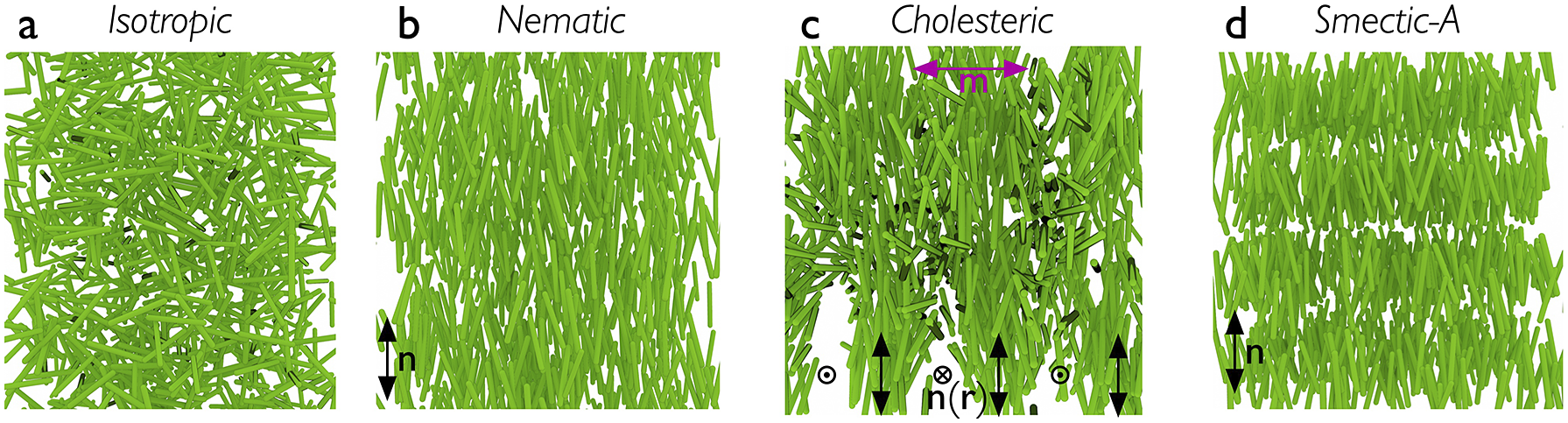
Figure 1. Highly schematic illustrations of the distribution of rod-shaped mesogens in (a) isotropic, (b) nematic, (c) cholesteric and (d) smectic-A phases. Note that the polymer backbone of a corresponding LCE is not depicted here. The apparent voids in the drawing of the cholesteric are artefacts of the way the 3D illustration was done, and the smectic positional order into layers is exaggerated for clarity in (d).
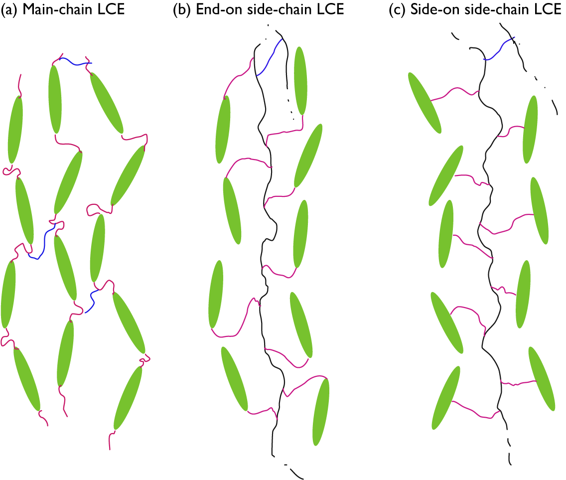
Figure 2. Highly schematic 2D illustrations of (a) main-chain, (b) end-on side-chain, and (c) side-on side-chain LCEs, all illustrated for the case of nematic order with director along the up–down direction in the figure. Mesogens are represented by green ellipsoids, spacers by pink wiggly lines, non-mesogenic backbones by black wiggly lines, and crosslinks by blue wiggly lines. For the two side-chain LCEs, crosslinks to another backbone are only hinted at the top of each drawing.
It is probably intuitive that the backbone is along n in case of main-chain and side-on side-chain LCEs, but this is normally the case also for end-on side-chain LCEs. At first sight, one might think that the mesogens would align perpendicular to the backbone to which they attach, but in many cases the spacer is sufficiently flexible to bend such that the mesogens align along the backbone even in this architecture. If this is not the case, a smectic phase, in which the mesogens organise into layers as illustrated in Figure 1(d), may be promoted, and then the backbone would be expected to stretch out perpendicular to n. Since the concept of a molecular chain is often connected to the notion of polymers, that is, with well over 20 repetitions of the monomer, the term side-chain LCE may in some sense be misleading. It is the main chain that is of polymeric size in this case, thus forming the elastomer, while the side ‘chains’ attaching the mesogens are the spacers, far below polymeric size. While side-chain LCE is the established term, a potentially more descriptive alternative might be ‘pendant LCE’, reflecting the incorporation of mesogens as pendants to the polymer backbone.
The class of LCs to which LCEs belong is called thermotropic, signifying that temperature is the main thermodynamic control variable. Heating above a temperature referred to as the clearing point, the LC order is lost and the material turns into a regular isotropic (I) liquid. The random arrangement of mesogens in the I phase is illustrated schematically in Figure 1(a). The name ‘clearing point’ refers to the change from scattering to transparent as an unaligned bulk LC material is heated into its isotropic phase. The change of shape, or actuation, of an LCE happens as it is passed through the clearing transition due to an external stimulus that reduces or removes the long-range order; as will become clear below, this stimulus is most often heating, but does not have to be.
The mode of the resulting actuation is determined by the ground state shape of the LCE in combination with the way in which the director varies in space, described by the director field n(r) (Warner and Terentjev, Reference Warner and Terentjev2007). The N–I transition leads to contraction of the polymer network along the local n and expansion in the perpendicular plane at every point in the LCE. Why? Because in the nematic state, the polymer chains are extended along n by the long-range orientational order, as schematically illustrated in Figure 3(a). This amounts to a significant reduction of conformational freedom and thus reduction of entropy for the polymer backbone, which corresponds to a positive contribution to the free energy. If the long-range order disappears, as during a transition to an I state, the polymer chains can drastically increase this entropy by adopting an isotropic random coil state (Figure 3(b)). Because the isotropic conformation has a lesser extension along the direction that was n in the nematic state, compared to the stretched-out conformation, the coil effectively shrinks along that direction as a result of the transition. And because the overall volume does not typically change significantly at the N–I transition, this shrinkage must be compensated by expansion in the perpendicular plane.
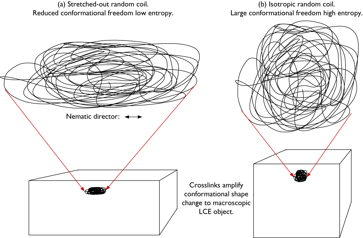
Figure 3. Highly schematic 2D illustrations of (a) a random coil that is stretched out along the horizontal direction and compressed along the vertical direction, as in a nematic LCE with horizontal director n, and (b) the same coil with retained topology after a transition to isotropic state, now with isotropic average random coil conformation since the stretching action given by the nematic order is gone. The two coil conformations are drawn with identical surface area, corresponding to retained volume in the real 3D case. The key difference between the two conformations is the much greater conformational freedom, and thus higher entropy, of the isotropic coil in (b). Thanks to the crosslinks, the conformational shape change is amplified to the entire LCE object (lower part).
Because all coils are connected with each other via the crosslinks in the volume-spanning rubber network, the molecular scale conformational changes are amplified to the macroscopic sample scale (Figure 3, lower row), and the entire LCE changes its shape in a way that reflects n(r) prior to the N–I transition. As we will see below, we can program LCEs to actuate in extremely diverse ways by playing with the ground state n(r) and shape of the LCE. Since we can, in principle, mold an LCE into any desired shape and program n(r) in diverse ways, the latter either congruent with the shape and boundary conditions or more or less independent of them, LCEs can simultaneously fill the function of motor and component that should move. This extraordinary combination of roles makes LCEs quite unique, offering a flexibility that conventional engineering solutions cannot match. Rather than adding a motor of some kind to each part of the construction that should be mobile, a designer working with LCEs could allow each design component to be its own motor. In the words of the Timothy White team (McCracken et al. Reference McCracken, Donovan and White2020): with LCEs, the material is the machine.
LCE actuation is fully reversible, generally occurs without fatigue, and it can be of very large magnitude; up to 400% length change has been confirmed experimentally. This very large-scale shape change, which LCEs have in common with conventional rubbers subject to an externally imposed stress, is very much due to the liquid-like dynamics at the molecular scale. Just like a conventional rubber is a liquid that is prevented from flowing by sparse crosslinks that turn the polymer into a volume-spanning network, an LCE is a liquid crystal that cannot flow for the same reason (Warner and Terentjev, Reference Warner and Terentjev2007). In many respects, we can consider an LCE actuator as a rubber that we do not need to stretch, since the stretching is done by the spontaneous liquid crystal ordering below the transition from the isotropic phase.
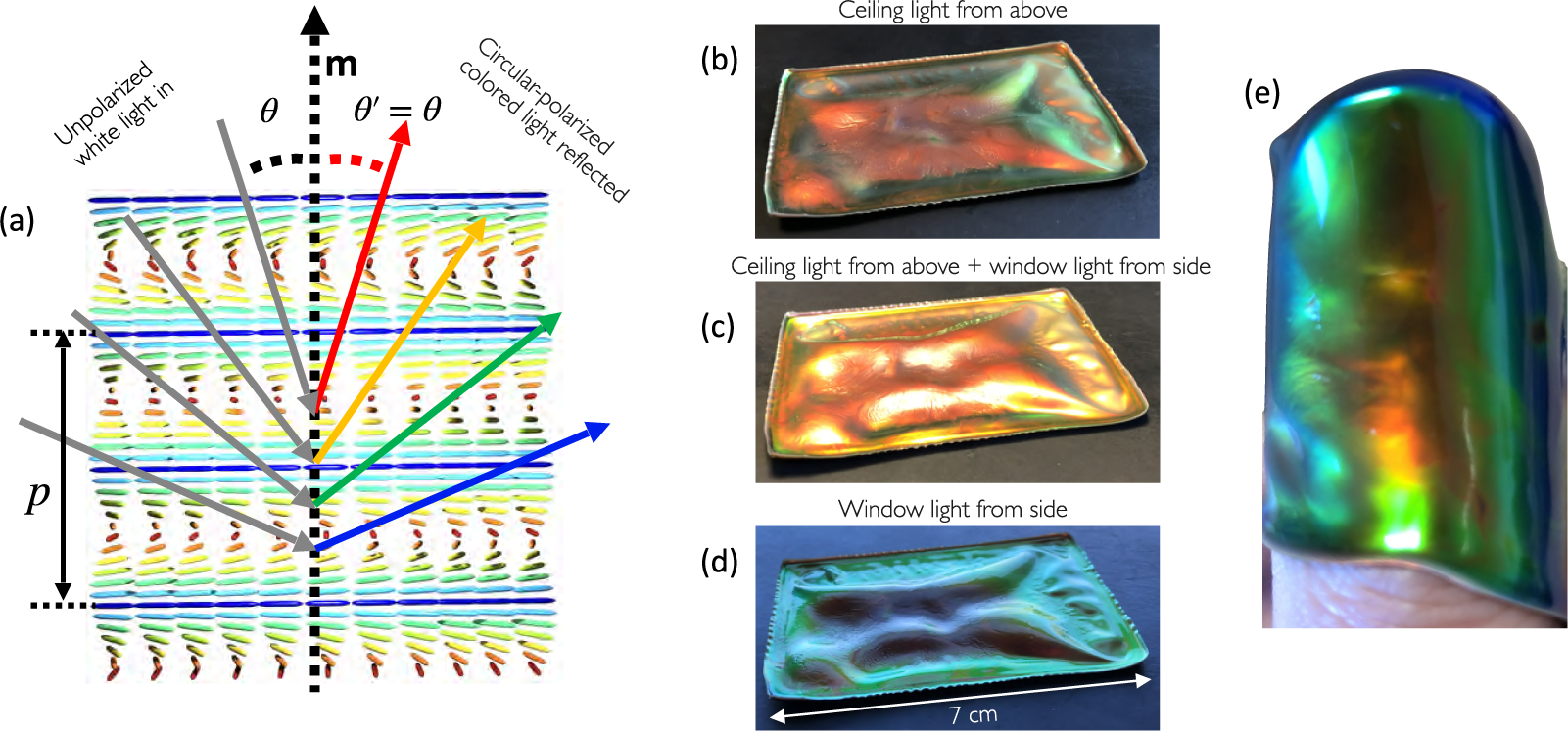
Figure 4. (a) Schematic illustration of the viewing angle dependence of the reflection colour from cholesteric liquid crystals (reproduced from Agha et al., (Reference Agha, Geng, Ma, Avşar, Kizhakidathazhath, Zhang, Tourani, Bavle, Sanchez-Lopez, Voos, Schwartz and Lagerwall2022) on CC-BY 4.0 license). (b–d) A buckled CLCE film (courtesy of R. Kizhakidathazhath) with red $\lambda _0$
viewed along roughly constant direction but with different illumination; (b) from an office sealing lamp above, (c) with light from the lamp and with daylight from the side through a window and (d) with only daylight from the side. (e) The same film wrapped around the author’s thumb, showing colour variations both due to varying
$\lambda _0$
viewed along roughly constant direction but with different illumination; (b) from an office sealing lamp above, (c) with light from the lamp and with daylight from the side through a window and (d) with only daylight from the side. (e) The same film wrapped around the author’s thumb, showing colour variations both due to varying $\theta $
and varying p, the latter due to varying degrees of stretching of the rubber in different regions.
$\theta $
and varying p, the latter due to varying degrees of stretching of the rubber in different regions.
The reverse effect to actuation is also possible, with an imposed mechanical deformation forcing the LCE in its liquid crystalline state to temporarily change its programmed ordering. The most spectacular example is that of cholesteric – also called chiral nematic – LCEs (CLCEs), exhibiting structural colour that can change across the entire visible spectrum in response to a mechanical strain (Finkelmann et al., Reference Finkelmann, Kim, Munoz, Palffy-Muhoray and Taheri2001; Mao et al., Reference Mao, Terentjev and Warner2001; Cicuta et al., Reference Cicuta, Tajbakhsh and Terentjev2004; Kizhakidathazhath et al., Reference Kizhakidathazhath, Geng, Jampani, Charni, Sharma and Lagerwall2020; Geng et al., Reference Geng, Kizhakidathazhath and Lagerwall2022; Kim et al., Reference Kim, Lee, Liu, Kim, Wang and Yang2022). A cholesteric is locally identical to a nematic, the difference being that n rotates continuously in a helical fashion along an axis m that is everywhere perpendicular to n, as illustrated in Figures 1(c) and 4(a). The colour of CLCEs is due to the periodic variation of the refractive index that results from this helically modulated n(r), creating a photonic bandgap:
 $$ \begin{align} \Delta \lambda=p\Delta n_{nh} \end{align} $$
centred around a central selective reflection wavelength (in air) $\lambda _r$
given by Bragg’s law as
$\lambda _r$
given by Bragg’s law as
 $$ \begin{align} \lambda_r=\bar{n}p\cos{\theta}=\lambda_0\cos{\theta}. \end{align} $$
Here, p is the pitch of the helix, $\Delta n_{nh}$
is the birefringence in the absence of helix (nh: non-helical), for instance, after mechanical unwinding,
$\Delta n_{nh}$
is the birefringence in the absence of helix (nh: non-helical), for instance, after mechanical unwinding, $\bar {n}$
is the average refractive index in the CLCE and
$\bar {n}$
is the average refractive index in the CLCE and $\theta $
is the angle of incidence between the illuminating light ray and m. Figure 4(a) illustrates some of these parameters graphically, as well as the resulting iridescence described by Equation (2), that is, a colour that blueshifts with increasing
$\theta $
is the angle of incidence between the illuminating light ray and m. Figure 4(a) illustrates some of these parameters graphically, as well as the resulting iridescence described by Equation (2), that is, a colour that blueshifts with increasing $\theta $
. As shown in Figure 4(b)–(e), the colour of one and the same cholesteric sample can change strongly as m varies with respect to viewing and/or illumination directions (each may have to be considered independently since we do not necessarily have specular reflection [Agha et al., Reference Agha, Geng, Ma, Avşar, Kizhakidathazhath, Zhang, Tourani, Bavle, Sanchez-Lopez, Voos, Schwartz and Lagerwall2022]). For this reason, it is convenient to use the maximum selective reflection wavelength,
$\theta $
. As shown in Figure 4(b)–(e), the colour of one and the same cholesteric sample can change strongly as m varies with respect to viewing and/or illumination directions (each may have to be considered independently since we do not necessarily have specular reflection [Agha et al., Reference Agha, Geng, Ma, Avşar, Kizhakidathazhath, Zhang, Tourani, Bavle, Sanchez-Lopez, Voos, Schwartz and Lagerwall2022]). For this reason, it is convenient to use the maximum selective reflection wavelength, $\lambda _0=\bar {n}p$
, corresponding to retroreflection, that is, with antiparallel illumination and viewing directions (
$\lambda _0=\bar {n}p$
, corresponding to retroreflection, that is, with antiparallel illumination and viewing directions ( $\theta =0$
), as a reference value to describe the colour of CLCEs. Since the helix couples to the LCE network, a mechanical strain perpendicular to m compresses the helix, reducing p and thus blueshifting
$\theta =0$
), as a reference value to describe the colour of CLCEs. Since the helix couples to the LCE network, a mechanical strain perpendicular to m compresses the helix, reducing p and thus blueshifting $\lambda _0$
. This mechanochromic response of CLCEs is very potent for diverse strain sensing applications.
$\lambda _0$
. This mechanochromic response of CLCEs is very potent for diverse strain sensing applications.
While this review focuses entirely on nematic and cholesteric LCEs, I will occasionally mention smectic order as well, since it occurred in the historical development, in theoretical discussions or in practically realised materials. As illustrated in Figure 1(d), smectic LCs exhibit a one-dimensional quasi-long-range positional order in addition to the long-range orientational order, in the form of mesogens organising into layers. The layer normal is along n in the simplest smectic-A phase, whereas it is tilted away from n in the smectic-C phase. Several more variants of smectic order exists, but they are not of importance for the discussion in this paper.
Before moving on, I point out that I do not cover liquid crystal gels in this review (apart from the very early speculations of de Gennes), referring the interested reader primarily to the works of Urayama et al. (Reference Urayama, Honda and Takigawa2005a,b) and Urayama (Reference Urayama2007). I also do not generally cover the rich body of research in glassy liquid crystal networks, often referred to as LCNs (White and Broer, Reference White and Broer2015). For clarity, I will refer to them as gLCNs, because semantically, LCN is a broader term that incorporates LCE as a subclass. Contrasting LCEs against LCNs can therefore lead to confusion. The reason that I do not review gLCN research, which is also the reason why I feel a stringent distinction is important, is that their physics of actuation is really quite different from that of the classic entropy-driven LCE actuation. While the latter is the strongest in the vicinity of the transition between liquid crystalline and isotropic phases, gLCNs do not exhibit such a transition since their long-range order is frozen in by the high-crosslink density; gLCNs have no clearing point. This applies also above the glass transition temperature $T_g$
. The actuation of gLCNs instead takes place more or less continuously over a broad temperature range, driven by their anisotropic thermal expansion (White and Broer, Reference White and Broer2015). The exceptions when I do discuss papers on gLCNs (which show great promise for many applications and are as fascinating as are LCEs) are when one can draw synthetic conclusions from those papers that are applicable also to LCEs. In doing so, I try to highlight the impact of the different chemical architectures and physics of actuation, cautioning that conclusions for one system can often only partially be applied to the other. On the other hand, we will see towards the end of Section 3 that also LCEs may actuate non-entropically, without approaching a clearing transition, and then their behaviour is qualitatively similar to that of gLCNs.
$T_g$
. The actuation of gLCNs instead takes place more or less continuously over a broad temperature range, driven by their anisotropic thermal expansion (White and Broer, Reference White and Broer2015). The exceptions when I do discuss papers on gLCNs (which show great promise for many applications and are as fascinating as are LCEs) are when one can draw synthetic conclusions from those papers that are applicable also to LCEs. In doing so, I try to highlight the impact of the different chemical architectures and physics of actuation, cautioning that conclusions for one system can often only partially be applied to the other. On the other hand, we will see towards the end of Section 3 that also LCEs may actuate non-entropically, without approaching a clearing transition, and then their behaviour is qualitatively similar to that of gLCNs.
The story so far: Milestones to the current state of the art of nematic and cholesteric LCEs
1969–1975: The theoretical foundation is laid in France
From the theoretical physics side, the seed to what grew into LCEs was planted by Pierre-Gilles de Gennes as early as 1969 (de Gennes, Reference de Gennes1969), discussing a system that was a bit different from what we understand under the concept LCE today. De Gennes considered what might rather be described as a hypothetical LC gel, with a regular polymer dissolved in a low molar mass LC solvent and then crosslinked. We now know that an LC solvent will tend to expel non-mesogenic polymers dissolved in it (Brochard, Reference Brochard1979; Samitsu et al., Reference Samitsu, Takanishi and Yamamoto2010), and practical LC gels, therefore, use a polymer network that is itself liquid crystalline, the solvent being liquid crystalline or isotropic (Urayama, Reference Urayama2007). Despite these differences, the discussion in de Gennes’ paper in fact predicted the key aspect of LCEs illustrated in Figure 3: a polymer network crosslinked under the influence of the long-range orientational order of LCs should adopt an anisotropic, ellipsoidal, random coil conformation, but it should relax into an isotropic, spherical, chain conformation if the surrounding is changed to isotropic. In the hypothetical gel case considered, de Gennes imagined the latter change to be realised by replacing the LC solvent with a regular isotropic solvent.
De Gennes also concluded that a network crosslinked in a smectic solvent should exhibit extremely anisotropic mechanical properties due to much stronger crosslinking parallel to the smectic planes than perpendicular to them. And for a network crosslinked in a cholesteric solvent, he expected that the resulting helicoidal modulation of the network stretching direction would prevent it from relaxing into an isotropic conformation even after removing the LC environment. This is a prediction of de Gennes’ that is not so often mentioned, but we will see later that it is correct and it can have profound consequences. Although he did not mention any expectation of actuation or any of the other peculiar properties that we today connect with LCEs, de Gennes noted that the networks formed under the influence of LC order ought to exhibit remarkable properties, for instance, in terms of optics. He also noted that a macroscopic alignment of the LC would be required to extend the network anisotropy to the overall sample scale.
Six years later, de Gennes followed up with a second landmark paper (de Gennes, Reference de Gennes1975), in which he took inspiration from recent experiments by Bouligand and co-workers, who had frozen in various liquid crystalline phases by polymerising them into densely crosslinked hard glassy solids (Bouligand et al., Reference Bouligand, Cladis, Liebert and Strzelecki1974). In modern terminology, the Bouligand paper belongs to the earliest reports on gLCNs. De Gennes speculated about the behaviour if the network were made sparsely crosslinked and if the mesogenic units were surrounded by sufficiently long and flexible spacer groups, expecting a soft liquid crystalline rubber in which there would be no need for the low molar mass nematic solvent from his 1969 paper. Considering both side- and main-chain LCE structures, he concluded that the former should have weaker coupling between nematic order and rubber elasticity, hence, he focused on the latter. He formulated the free energy function where thermal and mechanical contributions are coupled, concluding that it should be possible to induce the transition from a disordered isotropic phase to an ordered nematic phase by stretching this rubber. This article has often been cited as one where de Gennes predicted the actuation of LCEs upon inducing the nematic–isotropic phase transition, but the article actually contains no statement about this. One may, of course, argue that this was implicitly captured in his free energy equation, but there is no explicit prediction of actuation behaviour; the article focused on the opposite phenomenon, that is, a shift in the phase transition temperature driven by mechanical stretching of the LCE.
One of the many ways in which de Gennes was a remarkable liquid crystal researcher was that he, although being first and foremost a theoretical physicist, demonstrated a genuine interest in and a deep understanding of the organic chemistry of the materials he developed theory for. I recall being surprised by how much chemistry, including chemical reaction schemes, he presented during his last talk at an international liquid crystal conference (ILCC 2002 in Edinburgh), devoted to LCEs as artificial muscles. In order to have a repeated strong impact on an interdisciplinary field such as LCEs, as did de Gennes, it is imperative to embrace all the disciplines touched by the field. Nobody can be an expert in all fields, but consistently ignoring the chemistry or the physics because our primary expertise is in the opposite domain will leave us as tourists in a country that we may love but never fully understand. We will benefit from taking de Gennes’ broad interest and curiosity as a guideline and embracing all the stimulating aspects of the rich and fascinating field that is LCE research and applications.
1981–2000: Germany pioneers LCE chemistry
Twelve years passed between de Gennes’ first conceptual seed and the first realisation of an actual LCE, by Heino Finkelmann and co-workers in Clausthal-Zellerfeld, Germany (Finkelmann et al., Reference Finkelmann, Kock and Rehage1981). By attaching mesogenic pendants to a flexible polysiloxane backbone via 3- to 6-carbon alkyl chain spacers (see example in Figure 5), they created side-chain LCEs exhibiting nematic, smectic and cholesteric phases. The systems were lightly crosslinked by flexible decasiloxane bridges connecting one main chain to another. With these LCEs, the authors demonstrated the macroscopic ordering by mechanical stretching that de Gennes had predicted in 1975: the initially scattering polydomain LCE became transparent upon uniaxial stretching, indicating a uniform director orientation throughout the sample above a strain threshold. The cholesteric phase most likely had a helix pitch short enough to generate selective reflection, but without macroscopically uniform alignment of the helix it showed a mother of pearl character according to the authors, which is typical of an unaligned macroscopic sample of short-pitch cholesteric.

Figure 5. Backbone (a), mesogen (b) and crosslinker (c) used by Finkelmann et al. (Reference Finkelmann, Kock and Rehage1981) to make the first LCE, of nematic side-chain type (d), drawn with the same colour coding as in Figure 2. The scheme shows 11 repeat units of two polysiloxane backbones (black), crosslinked by a flexible decasiloxane spacer (blue) with four mesogen pendants (green) per backbone, separated by dimethylsiloxane units. Each mesogen is coupled to the backbone via a propoxy spacer (red), here drawn with a bent conformation to allow the mesogens to align along the backbone in a nematic arrangement. Note that the scheme is drawn in 2D for clarity, while the real system of course extends into all three dimensions. In the actual LCE, each backbone had about 120 statistically distributed repeat units, 6–12 of which constituted one end of a crosslink to one of the many adjacent backbones.
LCE chemistry was initially very much a German speciality, the activities in the Finkelmann group in Freiburg (to which the group moved soon after the first LCE paper) being paralleled by those of Rudolf Zentel and co-workers in Mainz. This group followed a slightly different chemical design approach, working with polyacrylates and polymethacrylates. They introduced the first main-chain LCEs in 1986 (Zentel and Reckert, Reference Zentel and Reckert1986), exhibiting only smectic phases. Zentel also demonstrated the first example of electric field-induced shape variation of an LCE, by grinding it into thin pieces that were then swelled in a low molar mass LC solvent (Zentel, Reference Zentel1986). In 1988, his group obtained nematic LCEs with mesogens in the backbone by combining main- and side-chain architectures (Bualek and Zentel, Reference Bualek and Zentel1988). Still there were no reports of the impressive shape change that we today consider as LCE actuation, driven by inducing the clearing transition. The papers at this time reported primarily on the mechanically induced ordering, sometimes detected by an opaque LCE turning transparent, sometimes via X-ray scattering.
Today, it is not uncommon to hear that de Gennes predicted LCEs theoretically and Finkelmann made the first LCE in practice, sometimes giving the impression that the first led to the second. However, reading the original papers, one notes that none of the early German works made reference to the work of de Gennes. It appears that early LCE theory and chemistry developed largely independent of one another, the German groups possibly being unaware of de Gennes’ papers on the topic at the time. De Gennes had published both his papers in the French language (Finkelmann’s and Zentel’s landmark papers were in English), the 1975 paper in the journal of the French academy of sciences, with a primarily French readership. Another important factor may be that the different teams approached the topic from different starting points; while de Gennes started by analysing LC gels from a theoretical physics perspective, Finkelmann and Zentel developed their first LCEs in the framework of the thriving field of side-chain liquid crystal polymers, originating in experimental work while the theory was not well developed at the time (Zentel, Reference Zentel1994). Perhaps, it was thus an unawareness of de Gennes’ work among the chemistry pioneers that delayed the practical attempts to address the second predicted requirement from de Gennes’ 1969 paper (de Gennes, Reference de Gennes1969), namely to ensure a uniform n(r) in the LCE ground state.
The breakthrough that took care of this issue for the first time was reported by the Finkelmann group in 1991 (Küpfer and Finkelmann, Reference Küpfer and Finkelmann1991), introducing a side-chain nematic LCE formed using two different crosslinking reactions, one rapid and one slow. The few rapidly formed crosslinks led to a weak initial polymer network forming, yet it was sufficiently strong to stretch and thereby impose a uniform director orientation. Leaving this mechanically strained state throughout the completion of the slow crosslinking reaction, the second network made the ordered ground state permanent. This resulted in the first nematic liquid single crystal elastomer (nowadays often called monodomain LCE), which retained the uniform director orientation and stretched-out polymer conformation even after the mechanical strain was removed. Of large relevance for this approach was the theoretical analysis of multi-stage crosslinking 4 years later by Verwey and Warner, concluding that the dual network has no impact on the final LCE behaviour, which should be identical to that of a single-network LCE (Verwey and Warner, Reference Verwey and Warner1995). Studying the shape deformation as a function of temperature, the Finkelmann team reported a 90% elongation along n when the system recovered its nematic order on cooling from the isotropic phase. This was thus the first report of actuation driven by the order–disorder phase transition in LCEs.
They also measured the orientational-order parameter S in the process. For an isotropic phase, $S=0$
, whereas a hypothetical perfectly ordered phase would have
$S=0$
, whereas a hypothetical perfectly ordered phase would have $S=1$
; for nematics, we typically have
$S=1$
; for nematics, we typically have $S=0.4$
–
$S=0.4$
– $0.7$
. Kupfer and Finkelmann found the typical behaviour of LCEs with what appears to be a continuous transition to isotropic, contrasting with the expected first-order (discontinuous) N–I transition of thermotropic liquid crystals. They also found some residual non-zero order above the clearing point. A few years earlier, Schätzle and Finkelmann had explained this behaviour as an artefact arising from an extended nematic–isotropic phase coexistence range which can be understood by considering the LCE as an intrinsic two-component system that combines the non-mesogenic polymer backbone and crosslinks with the LC-promoting mesogenic pendants, as well as the impact of the crosslinks on the conformational freedom of the polymer main chains (Schätzle and Finkelmann, Reference Schätzle and Finkelmann1987). As with any LC mixture, one should thus, for LCEs, consider a clearing range rather than clearing point for the LC–isotropic transition. Some 15 years later, the Terentjev team analysed the issue in more detail, concluding that the crosslinked network turns the nematic–isotropic transition supercritical by, on the one hand, creating a molecular ordering field active even above the clearing point and/or, on the other hand, creating random sources of disorder that disturb the nematic phase formation at lower temperatures (Hogan and Tajbakhsh, Reference Hogan, Tajbakhsh and Terentjev2002).
$0.7$
. Kupfer and Finkelmann found the typical behaviour of LCEs with what appears to be a continuous transition to isotropic, contrasting with the expected first-order (discontinuous) N–I transition of thermotropic liquid crystals. They also found some residual non-zero order above the clearing point. A few years earlier, Schätzle and Finkelmann had explained this behaviour as an artefact arising from an extended nematic–isotropic phase coexistence range which can be understood by considering the LCE as an intrinsic two-component system that combines the non-mesogenic polymer backbone and crosslinks with the LC-promoting mesogenic pendants, as well as the impact of the crosslinks on the conformational freedom of the polymer main chains (Schätzle and Finkelmann, Reference Schätzle and Finkelmann1987). As with any LC mixture, one should thus, for LCEs, consider a clearing range rather than clearing point for the LC–isotropic transition. Some 15 years later, the Terentjev team analysed the issue in more detail, concluding that the crosslinked network turns the nematic–isotropic transition supercritical by, on the one hand, creating a molecular ordering field active even above the clearing point and/or, on the other hand, creating random sources of disorder that disturb the nematic phase formation at lower temperatures (Hogan and Tajbakhsh, Reference Hogan, Tajbakhsh and Terentjev2002).
Nine years after the introduction of the two-stage crosslinking approach, this was for the first time applied to pure main-chain nematic LCEs (Figure 6), again by the Finkelmann group (Donnio et al., Reference Donnio, Wermter and Finkelmann2000). By stretching a loosely crosslinked solvent-rich gel prior to final crosslinking, a monodomain main-chain nematic LCE was obtained.

Figure 6. Mesogen (a), chain extender (b) and crosslinker (c) used by Donnio et al. (Reference Donnio, Wermter and Finkelmann2000) to make the first nematic main-chain LCE (d), drawn with the same colour coding as in Figure 2: mesogens in green, spacers/chain extenders in red and crosslinker in blue. Note that the scheme is drawn in 2D for clarity, while the real system of course extends into all three dimensions. The disiloxane chain extenders and tetrasiloxane crosslinkers were statistically distributed, with one crosslinker for every 18 chain extenders.
The nineties and the start of the new millennium: LCEs mature into artificial muscles
The concept of LCE-based actuation and the realisation of its practical application potential gradually developed, and in 1997, 16 years after the first LCEs were realised in practice, de Gennes and co-workers published a paper where they promoted LCEs as a better alternative for artificial muscles than the solvent swelling/deswelling-based gel actuators that were dominating the discussion at the time (de Gennes et al., Reference de Gennes, Hébert and Kant1997). They pointed out that, first, LCEs should be much faster, benefitting from being limited by thermal rather than matter diffusion, the former two orders of magnitude faster than the latter. Second, LCEs should also be much more robust since the LCE actuation is not subject to the enormous swelling stress that gels experience between their swollen and unswollen regions during solvent in-flow. This easily leads to rupture, especially if subjected to load, as any muscle in use will be. They analysed the LCE actuation potential critically, concluding that LCEs should be able to compete with natural muscles in terms of their actuation speed. Although the title of the paper referred to ‘nematic gels’, the authors pointed out that their analysis holds also for solvent-free nematic LCEs.
It took until 2001 until also experimental papers referred to LCEs directly as artificial muscles, first by the Finkelmann team presenting a monodomain side-chain LCE that was crosslinked by a main-chain LCE (Wermter and Finkelmann, Reference Wermter and Finkelmann2001), and then in a transatlantic collaboration between the Naval Research Laboratory in Washington, DC and the Institut Curie in Paris, featuring the foremost French LCE chemist, Patrick Keller (Thomsen III et al., Reference Thomsen, Keller, Naciri, Pink, Jeon, Shenoy and Ratna2001). Both papers put LCEs to the test regarding their performance as actuators, the former finding a remarkable actuation stroke of almost 400%, the second carrying out multiple quantitative measurements of actuation speed and power, confirming the de Gennes team’s expectation that LCEs may compete with natural muscles.
Both papers were also milestones from the LCE architecture point of view, the Finkelmann team paper through its use of a side-chain LCE with main-chain crosslinker, the other one being the first example of a side-on side-chain-LCE, see Fig. 7. The mesogenic monomer they used was initially published by the Keller team in 1993 (Leroux et al., Reference Leroux, Keller, Achard, Noirez and Hardouin1993), inspired by the first report of a side-on side-chain liquid crystal polymer by Hessel and Finkelmann in 1985 (Hessel and Finkelmann, Reference Hessel and Finkelmann1985), and following an earlier variation by Keller in 1988 (Keller et al., Reference Keller, Hardouin, Mauzac and Achard1988). All these earlier papers (as well as a few other related papers inspired by the Hessel and Finkelmann report) were variations on the same mesogenic monomer design theme, incorporating three alkyl chains: two relatively short non-reactive ones at each mesogen end and a third acrylate-terminated alkyl chain extending laterally from the middle of the mesogen core (see Figure 7(a)). But none of the earlier studies discussed the possibility of elastomeric behaviour or considered the idea to crosslink the system. This was the key novelty of the 2001 paper. However, already in their 1993 paper, the Keller team noted that the side-on side-chain design was particularly powerful in extending the polymer backbone along n, hence, the choice to use this monomer (which is now by many simply called ‘The Keller monomer’) was natural when they took the step to making an LCE for realising efficient artificial muscles.

Figure 7. Mesogen (a) and crosslinker (b) used by Thomsen III et al. (Reference Thomsen, Keller, Naciri, Pink, Jeon, Shenoy and Ratna2001) to make the first nematic side-on side-chain LCE (c), drawn with the same colour coding as in Figure 2: backbone in black, mesogens in green, spacers in red and crosslinker in blue. The scheme is drawn in 2D although it leads to an overcrowding of the structure, preventing the drawing of any mesogens on the second backbone. In the real system, the mesogens surround the main chain in all three dimensions. The actual LCE had one crosslinker for every nine mesogens.
The NRL-Curie paper was seminal also in its approach to align LCEs into monodomains, because for the first time, this was done in the same way as low molar mass LCs are aligned for display applications, by filling the precursor into a cell consisting of two parallel glass plates with rubbed aligning layers, here, wisely chosen to be made of the water-soluble polymer polyvinyl alcohol (PVA). Apart from the mesogenic monomer, only a photoinitiator and regular hexane diacrylate as crosslinker (Figure 7(b)) were added, yielding a low-viscous mixture that could easily be filled into the cell by capillary action while heated. Upon slow cooling from the isotropic to the nematic state, the latter spontaneously developed with the uniform n(r) imposed by the rubbed PVA layers. The polymerisation into an LCE was then photoinitiated by UV-irradiation (the entire handling must thus be done in yellow light to avoid premature polymerisation). This avoids the need for dual networks and intermediate prestretching, and it gives a flat LCE film with perfectly defined thickness, shape and director field configuration. After polymerisation, the cell was opened and placed in hot water to dissolve the PVA, which allowed the LCE film to be easily harvested. The drawbacks of this approach are that it works only for limited thicknesses, since surface alignment is not very efficient beyond about 100 $\mu $
m cell gap, and that the process is somewhat cumbersome and wasteful, since each LCE fabrication sacrifices a cell. Nevertheless, this way of making LCEs has become a standard approach over the years which is still largely in use.
$\mu $
m cell gap, and that the process is somewhat cumbersome and wasteful, since each LCE fabrication sacrifices a cell. Nevertheless, this way of making LCEs has become a standard approach over the years which is still largely in use.
The team followed up with another landmark paper in 2003, presenting the first LCE fibre actuators prepared by simple hand drawing out of the precursor melt (Naciri et al., Reference Naciri, Srinivasan, Jeon, Nikolov, Keller and Ratna2003). They used the same lateral reactive side-chain monomer but this time they started by making a linear terpolymer (including two variations of the basic mesogen structure as pendants and a non-mesogenic pendant with a reactive site to enable crosslinking), and then they started slow thermal crosslinking by mixing in the crosslinker and stirring at an elevated temperature at which the mixture was in a nematic state. Once a notable viscosity increase was detected, a sufficient degree of crosslinking had completed to allow rapid hand drawing of a filament from the precursor mixture, after which they left the filament to rest until crosslinking was complete. The drawing process oriented n along the drawing direction, hence, the fibres were very well aligned. Excellent muscle performance was demonstrated, with a retractive stress of nearly 300 kPa. They demonstrated how a single fibre could lift a 200 mg weight upon heating past the nematic–isotropic transition, leading to a reversible length contraction of 30–35%. They also introduced carbon nanotubes (CNTs) into an LCE for the first time, with the intention to increase the speed of heat diffusion throughout the LCE. It is unclear if a faster response was achieved, but the CNT doping reduced the temperature range for complete actuation and also reduced the threshold temperature. We will see in the next section that CNT doping can be useful also for other purposes.
An alternative to control the LCE director field is magnetic field-driven programming of n(r), initially used by Mitchell and co-workers (Legge et al., Reference Legge, Davis and Mitchell1991) for imprinting a uniform director field, and then revived at regular intervals, for example, by the Zentel group in 2014 (Schuhladen et al., Reference Schuhladen, Preller, Rix, Petsch, Zentel and Zappe2014) and by the Aizenberg group more recently (Waters et al., Reference Waters, Li, Yao, Lerch, Aizenberg, Aizenberg and Balazs2020; Li et al., Reference Li, Lerch, Waters, Deng, Martens, Yao, Kim, Bertoldi, Grinthal, Balazs and Aizenberg2022). While it is a powerful technique, it requires rather slow cooling from the isotropic phase in the presence of the magnetic field, which makes the scalability to industrial yields challenging. Given the options of other more recent developments (to be discussed below), it must be considered a bit of a niche option, useful in certain specific cases.
2001 and onwards: Light is the new heat
Because LCE actuation fundamentally is the result of a phase transition between an ordered nematic and a disordered isotropic state, the classic trigger for LCE actuation is heat to induce the phase transition, the relaxation requiring a corresponding cooling process. For many purposes, other triggers like electric fields, light or humidity would be more useful. The first of these alternative triggers to enter the field was light, the groundbreaking paper again coming from the Finkelmann group (Finkelmann et al., Reference Finkelmann, Nishikawa, Pereira and Warner2001). By incorporating an azobenzene dye with reactive end groups (Figure 8(a)) as crosslinker in a polysiloxane backbone side-chain LCE, the team demonstrated reversible photo-actuation based on the UV-triggered trans $\rightarrow $
cis isomerisation from a nematic-promoting rod shape to a disordering kink shape. Upon UV-irradiation of the LCE kept at a temperature where it is close to, but not above, its clearing point, the same degree of contraction along n was obtained as when heating above the clearing point. After turning off the UV-lamp, the azobenzene crosslinkers should relax back to the original rod shape, allowing the nematic phase to reform with a consequent extension of the LCE along the director back to its original shape. Both effects appeared to be demonstrated in the paper, with shortening of the LCE along n during UV-irradiation and recovery of the original shape after turning off the lamp. But the effect was slow, requiring on the order of an hour to reach saturation in either direction.
$\rightarrow $
cis isomerisation from a nematic-promoting rod shape to a disordering kink shape. Upon UV-irradiation of the LCE kept at a temperature where it is close to, but not above, its clearing point, the same degree of contraction along n was obtained as when heating above the clearing point. After turning off the UV-lamp, the azobenzene crosslinkers should relax back to the original rod shape, allowing the nematic phase to reform with a consequent extension of the LCE along the director back to its original shape. Both effects appeared to be demonstrated in the paper, with shortening of the LCE along n during UV-irradiation and recovery of the original shape after turning off the lamp. But the effect was slow, requiring on the order of an hour to reach saturation in either direction.
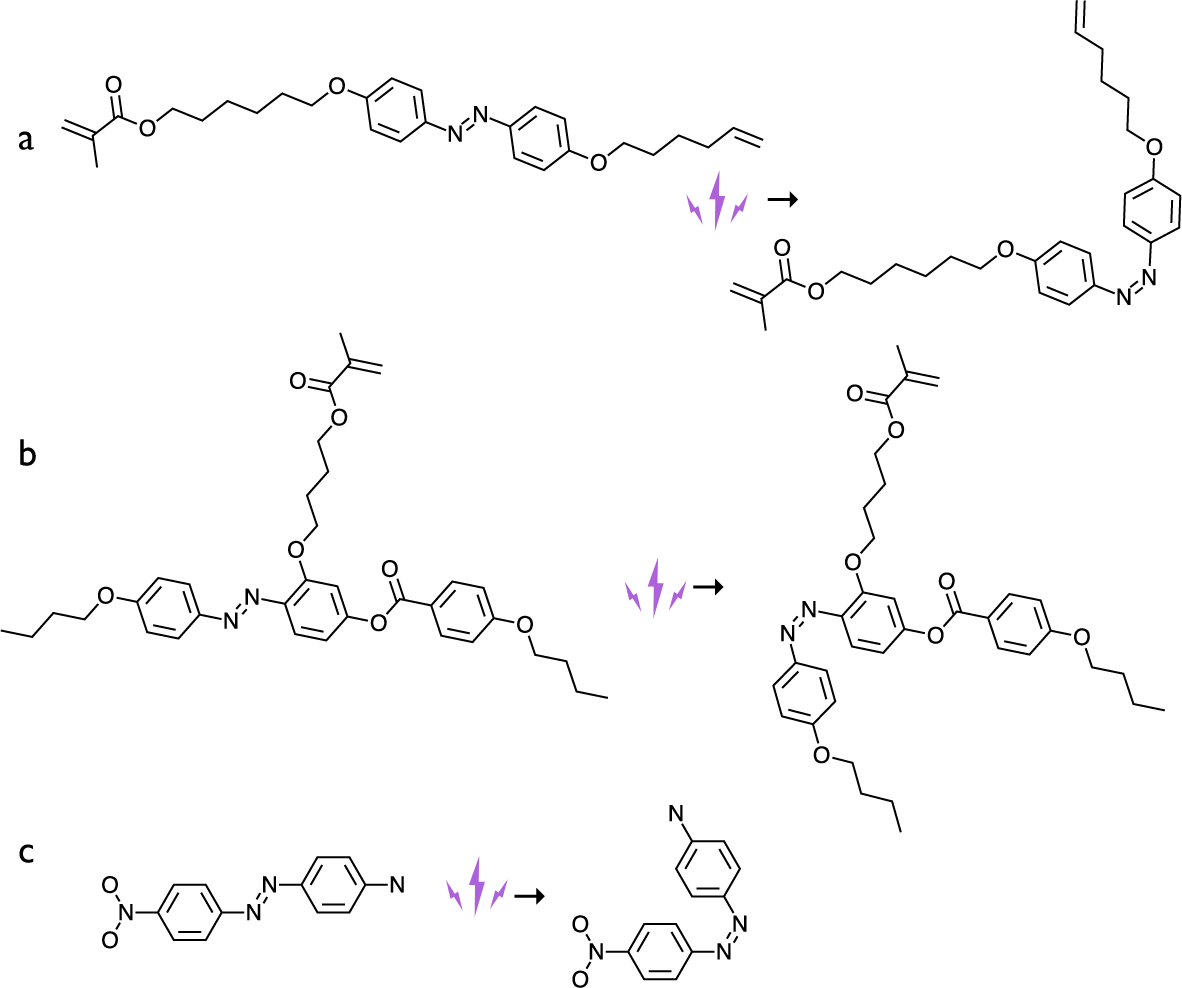
Figure 8. Three types of azobenzene dyes used in the early LCE photoactuation experiments, in their trans conformation on the left and cis conformation on the right. (a) The azobenzene dye crosslinker used by Finkelmann et al. (Reference Finkelmann, Nishikawa, Pereira and Warner2001). (b) The azobenzene dye side-on side-chain mesogenic monomer used by Li et al. (Reference Li, Keller, Li, Wang and Brunet2003). (c) The Disperse Orange I dye, with strong donor–acceptor (electron push–pull) configuration, used as a dopant by Camacho-Lopez et al. (Reference Camacho-Lopez, Finkelmann, Palffy-Muhoray and Shelley2004).
The second paper on photo-actuated LCEs, published by the Cambridge group of Eugene Terentjev (Hogan and Tajbakhsh, Reference Hogan, Tajbakhsh and Terentjev2002), is equally important, combining high ambitions and a rigorous approach with clarity and richness in details. Although this was very soon after the first demonstration of the concept, the team already here presented a systematic study of the impact of introducing azobenzene moieties in different functions of the LCE architecture, at varying concentration, and they carried out a careful and quantitative study of the actuation as well as temperature variation within the LCE upon UV actuation. Combining these rich data with an elegant theoretical analysis of the nature of the N–I phase transition as well as of the isomer population dynamics upon and after UV irradiation, and applying the result to the function describing the actuation magnitude versus orientational-order parameter, they could fit the data with impressive fidelity and detail. Most importantly, their study concluded that the azobenzene-functionalised LCE response to UV irradiation is more complex than what one might initially think: it combines the reduction of the clearing temperature $T_{NI}$
induced by the trans
$T_{NI}$
induced by the trans $\rightarrow $
cis isomerisation (this is often called the photochemical effect, a terminology I will use in the following) with a quite significant LCE-internal heating arising from the continuously on-going exothermic cis
$\rightarrow $
cis isomerisation (this is often called the photochemical effect, a terminology I will use in the following) with a quite significant LCE-internal heating arising from the continuously on-going exothermic cis $\rightarrow $
trans back relaxation (the photothermal effect).
$\rightarrow $
trans back relaxation (the photothermal effect).
Terentjev shares with de Gennes the broad perspective to LCEs, both being theoretical physicists with genuine interest and understanding of chemistry. But Terentjev goes even further, having built up a full-fledged chemistry lab at Cavendish, thereby creating a very strong environment that is capable of simultaneously pushing theory and practice forward. It is this combination of in-house theoretical physics and organic chemistry that made the 2002 paper possible, and we will see below that the Terentjev group has continued to push the envelope of LCE chemistry, also with some very important recent breakthroughs.
While the actuation in these two first papers on photoresponsive LCEs was slow, requiring more than an hour for saturated response, the next 2 years saw the response time decrease greatly, in two important further reports on LCE photoactuation. First, Patrick Keller’s team published the first photo-actuated side-on side-chain LCE, made by photopolymerisation (Li et al., Reference Li, Keller, Li, Wang and Brunet2003). This required, first, the introduction of a new azobenzene-substituted version of their side-on mesogenic monomer (Figure 8(b)), as well as the use of a photoinitiator triggered by near-infrared light. Although it was not mentioned, the entire process between addition of the photoinitiator and photopolymerisation must have taken place in complete darkness in order to avoid premature polymerisation. The most significant difference in these LCEs compared to the earlier Finkelmann and Terentjev reports was the much faster response time, on the order of 10 s. The reason for the difference is not clarified in the paper, but with today’s understanding, we may provide some suggestions.
It is important to note that this system is a true LCE and not a gLCN, as is clear from the fact that there is a nematic–isotropic transition and that the actuation versus temperature curve clearly localises the main actuation in the vicinity of the clearing transition. What the system has in common with many gLCN papers, however, is the sample geometry: the Keller LCE was a 20 $\mu $
m thick flat film fabricated between glass substrates with aligning layers, while the earlier photoresponsive LCEs were made using Finkelmann’s two-stage crosslinking and intermediate prestretching. The Terentjev LCEs were 0.4 mm thick, thus, 20 times that of the Keller team’s sample. Since the azobenzene moieties absorb the UV light that is used as trigger, a thick sample may have slowed-down response because the interior is reached by less UV light than the face exposed to the light source. Another important aspect was that the Keller team did not measure the temperature of their LCE during UV-irradiation. As clearly proven by (Hogan and Tajbakhsh, Reference Hogan, Tajbakhsh and Terentjev2002), the back relaxation of isomerised azobenzenes releases significant amounts of heat, hence, it could be that the thin sheets containing a minimum of 25% azobenzene dye mesogens had an internal temperature during UV-irradiation that was well above the temperature prior to irradiation.
$\mu $
m thick flat film fabricated between glass substrates with aligning layers, while the earlier photoresponsive LCEs were made using Finkelmann’s two-stage crosslinking and intermediate prestretching. The Terentjev LCEs were 0.4 mm thick, thus, 20 times that of the Keller team’s sample. Since the azobenzene moieties absorb the UV light that is used as trigger, a thick sample may have slowed-down response because the interior is reached by less UV light than the face exposed to the light source. Another important aspect was that the Keller team did not measure the temperature of their LCE during UV-irradiation. As clearly proven by (Hogan and Tajbakhsh, Reference Hogan, Tajbakhsh and Terentjev2002), the back relaxation of isomerised azobenzenes releases significant amounts of heat, hence, it could be that the thin sheets containing a minimum of 25% azobenzene dye mesogens had an internal temperature during UV-irradiation that was well above the temperature prior to irradiation.
The second landmark paper was again with Finkelmann (Camacho-Lopez et al., Reference Camacho-Lopez, Finkelmann, Palffy-Muhoray and Shelley2004), but this time, the azobenzene was not covalently linked to the network but instead added as a dopant. A non-reactive azobenzene dye (Disperse Orange I, Figure 8(c)) was infused into a ready-made nematic side-chain LCE by soaking the latter in a toluene solution of the dye, and then removing the LCE and evaporating the toluene. The resulting LCEs responded extremely fast (20 ms actuation and 75 ms relaxation time) and strongly to UV light irradiation. Comparing the same dye doped into side-chain LCEs without azobenzene with similar LCEs with azobenzene side-chain moieties, Harvey and Terentjev confirmed that the LCE with infused dye actuates much faster than the LCE with covalently bonded azobenzene (Harvey and Terentjev, Reference Harvey and Terentjev2007). They suggested that the ability of the dye to freely diffuse may have been important to explain this effect but also noted that the infused dye had a strong donor–acceptor (also called electron push–pull) configuration, in contrast to the covalently bonded azobenzene. This should give the infused dye a much faster relaxation. We will see in a moment that the latter difference may have been the key one.
The question of which was the dominating effect, photothermal or photochemical, remained debated for a long time, with several papers presenting data in favour of one or the other. Initially, the notion that the photochemical effect was dominant prevailed, first based on the notion that a temperature control system surrounding the LCE should compensate for internal heating (Hogan and Tajbakhsh, Reference Hogan, Tajbakhsh and Terentjev2002) and then on the observation that polydomain azobenzene-functionalised gLCN films responded to exposure to linearly polarised light by bending around an axis that was perpendicular to the light polarisation (Yu et al., Reference Yu, Nakano and Ikeda2003), a sensitivity which ought to be cancelled by heat diffusion if the photothermal effect were dominant (Corbett and Warner, Reference Corbett and Warner2009). However, this conclusion was challenged, first by the surprising observation that even a non-isomerisable dye like the anthraquinone-based Disperse Blue, which can only exhibit a photothermal effect, induced the same photoactuation as azobenzene dyes (Marshall and Terentjev, Reference Marshall and Terentjev2013).
Recently, da Cunha et al. carried out an elegant and highly clarifying study on photoactuation of gLCNs, Pilz da Cunha et al. (Reference Pilz da Cunha, van Thoor, Debije and Broer2019) allowing the impact of the photothermal effect to be effectively cancelled out. They prepared gLCN films with three strategically designed azobenzenes, covalently bonded to the network, and compared the photoactuation in air and in water. Two of the azobenzenes were monoacrylates, thus, forming pendants bound only to one backbone, while the third was a diacrylate, thus, acting as a crosslinker. The crosslinker and one of the two pendants were both designed without any strong donor–acceptor configuration, giving the cis state a lifetime on the order of hours. The other pendant, in contrast, was designed similar to Disperse Orange I, with a strong donor–acceptor configuration. The authors did not state a value for its cis state life time but they noted that this azobenzene exhibits only a single peak in the absorption spectrum, corresponding to the trans $\rightarrow $
cis isomerisation; apparently the cis state relaxes back to the trans state so quickly after isomerisation that effectively no cis isomers are present to absorb light. If they were present, they would have absorbed at a longer wavelength compared to the absorption of the trans isomer.
$\rightarrow $
cis isomerisation; apparently the cis state relaxes back to the trans state so quickly after isomerisation that effectively no cis isomers are present to absorb light. If they were present, they would have absorbed at a longer wavelength compared to the absorption of the trans isomer.
This difference in isomerisation dynamics is important and it explains much of the confusion in the early studies. None of the azobenzenes used in the original Finkelmann paper (Finkelmann et al., Reference Finkelmann, Nishikawa, Pereira and Warner2001) and in the follow-up paper by Hogan and Terentjev (Hogan and Tajbakhsh, Reference Hogan, Tajbakhsh and Terentjev2002) had any strong donor–acceptor configuration, hence, we can expect a relaxation time on the order of hours for the photoinduced cis state in those studies. In the Camacho-Lopez study, in contrast, the dye should have relaxed nearly instantaneously. The difference in population dynamics impacts the outcome of experiments in three fundamental ways. First, in the two early papers, UV-irradiation should have created a large population of cis isomers acting as disordering impurities, promoting the photochemical effect, whereas the rapid back isomerisation of the Disperse Orange I should have made that effect negligible in the Camacho-Lopez study. Second, that rapid back isomerisation also means that the dye in the latter study released any absorbed light energy as heat almost immediately after the photon absorption, driving a significant temperature increase and thus promoting the photothermal effect. Also in the earlier experiments, there must have been a temperature increase due to back relaxation, but it should have been more moderate due to the longer lifetime of the excited state. Third, fast relaxation continuously resets the system such that the dye is ready to absorb a new UV photon, release heat again, and so on, further amplifying the photothermal effect. Summarising, with Disperse Orange I or any other azobenzene with strong donor–acceptor configuration, the photothermal effect should dominate strongly since very few cis isomers are present at any point in time, giving little disturbance of nematic order, and since such dyes constantly absorb UV photons only to immediately release the energy again as heat.
Da Cunha et al. demonstrated these differences by comparing the temperature increase during photoactuation of their gLCNs in air, where heat dissipation from a film is slow. All three films actuated quickly and qualitatively similarly and all showed a linear temperature increase with light intensity. However, the slope was significantly higher for the film made with fast-relaxing azobenzene, also resulting in a much greater absolute temperature increase compared to the films incorporating slow-relaxing azobenzenes. The temperature increase was significant: from a starting temperature of 22–25 $^{\circ }$
C, the film with fast-relaxing azobenzene acquired a temperature of nearly 75
$^{\circ }$
C, the film with fast-relaxing azobenzene acquired a temperature of nearly 75 $^{\circ }$
C for a light intensity of 100 mW/cm
$^{\circ }$
C for a light intensity of 100 mW/cm $^2$
. Interestingly, when they repeated the experiments with the films immersed in water, both gLCNs made with pendant azobenzenes stopped responding while the film made with crosslinker azobenzene continued to respond. The greater heat conductance and heat capacity of the liquid water surrounding the thin gLCN films (they were only 20
$^2$
. Interestingly, when they repeated the experiments with the films immersed in water, both gLCNs made with pendant azobenzenes stopped responding while the film made with crosslinker azobenzene continued to respond. The greater heat conductance and heat capacity of the liquid water surrounding the thin gLCN films (they were only 20 $\mu $
m thick) led to almost immediate dissipation of heat, basically removing the photothermal effect. The reason that the third film kept responding is that its azobenzene, in its role as a crosslinker, can provide a ‘network pull’ effect that actuates the gLCN regardless of temperature. In other words, in gLCNs, the azobenzene crosslinker provides a photomechanical actuation whereas pendant azobenzenes can actuate only via the photothermal effect.
$\mu $
m thick) led to almost immediate dissipation of heat, basically removing the photothermal effect. The reason that the third film kept responding is that its azobenzene, in its role as a crosslinker, can provide a ‘network pull’ effect that actuates the gLCN regardless of temperature. In other words, in gLCNs, the azobenzene crosslinker provides a photomechanical actuation whereas pendant azobenzenes can actuate only via the photothermal effect.
I emphasise that the above conclusions are for gLCNs, because they cannot simply be transferred to LCEs. While the experiment of da Cunha et al. was extremely powerful in isolating the impact of the photothermal effect, we must consider the different physics of LCE and gLCN actuation to extrapolate the results. To make this clearer, let us look a bit closer at how the orientational order changes with temperature and UV irradiation in a photoresponsive LCE.
Recall that the primary impact of the photochemical effect in nematic LCEs is to reduce the transition temperature $T_{NI}$
from its value
$T_{NI}$
from its value $T_{NI}^0$
prior to photoisomerisation of the azobenzene units. The continuous curve in Figure 9 shows a typical behaviour of S versus temperature T, for a value
$T_{NI}^0$
prior to photoisomerisation of the azobenzene units. The continuous curve in Figure 9 shows a typical behaviour of S versus temperature T, for a value $T_{NI}^0=50^{\circ }$
C. All curves in the figure are calculated as
$T_{NI}^0=50^{\circ }$
C. All curves in the figure are calculated as $S=0.27(T-T_{NI})^{0.25}$
, which gives a reasonable approximation of the empirically observed behaviour (de Gennes and Prost, Reference de Gennes and Prost1993). This idealised model neglects the first-order nature of the clearing transition expected for low molar mass LCs but, as explained above, this is reasonable when considering the practical behaviour with an extended clearing temperature range of LCEs.
$S=0.27(T-T_{NI})^{0.25}$
, which gives a reasonable approximation of the empirically observed behaviour (de Gennes and Prost, Reference de Gennes and Prost1993). This idealised model neglects the first-order nature of the clearing transition expected for low molar mass LCs but, as explained above, this is reasonable when considering the practical behaviour with an extended clearing temperature range of LCEs.

Figure 9. Idealised plots of the nematic orientational-order parameter S as a function of temperature, for three different clearing points $T_{NI}=50^{\circ }, 47^{\circ }$
and
$T_{NI}=50^{\circ }, 47^{\circ }$
and $40^{\circ }$
C, respectively. The two lower values represent the effect of pure photochemical effect of azobenzene dyes in an LC environment upon UV-induced trans
$40^{\circ }$
C, respectively. The two lower values represent the effect of pure photochemical effect of azobenzene dyes in an LC environment upon UV-induced trans $\rightarrow $
cis isomerisation. At five temperatures, indicated by vertical arrows, the values of S of the three curves are compared, to highlight how the performance of photoactuated LCEs driven by the photochemical effect depends on operating temperature, initial clearing temperature and the impact of the azobenzene isomerisation on the clearing temperature.
$\rightarrow $
cis isomerisation. At five temperatures, indicated by vertical arrows, the values of S of the three curves are compared, to highlight how the performance of photoactuated LCEs driven by the photochemical effect depends on operating temperature, initial clearing temperature and the impact of the azobenzene isomerisation on the clearing temperature.
Let us first assume that we have a moderate photochemical effect, reducing the transition temperature to $T_{NI}^{UV1}=47^{\circ }$
C. This leads to the dashed curve. As is clear to see, the UV irradiation would have a quite strong effect on S even without any photothermal heating if the operating temperature is
$T_{NI}^{UV1}=47^{\circ }$
C. This leads to the dashed curve. As is clear to see, the UV irradiation would have a quite strong effect on S even without any photothermal heating if the operating temperature is $T=47^{\circ }$
C, identical to
$T=47^{\circ }$
C, identical to $T_{NI}^{UV1}$
. We here see the maximum UV-induced reduction of order, from the initial
$T_{NI}^{UV1}$
. We here see the maximum UV-induced reduction of order, from the initial $S^0\approx 0.36$
to the
$S^0\approx 0.36$
to the $S^{UV1}=0$
of a disordered state. However, if we change the operation temperature by only
$S^{UV1}=0$
of a disordered state. However, if we change the operation temperature by only $\pm 2^{\circ }$
C, the performance decreases considerably. At
$\pm 2^{\circ }$
C, the performance decreases considerably. At $T=49^{\circ }$
C the UV irradiation still induces an isotropic phase, but the starting order is already reduced by the higher operating temperature, so the reduction in S is lower,
$T=49^{\circ }$
C the UV irradiation still induces an isotropic phase, but the starting order is already reduced by the higher operating temperature, so the reduction in S is lower, $\Delta S\approx -0.27$
. At
$\Delta S\approx -0.27$
. At $T=45^{\circ }$
C, the UV irradiation is far from causing the transition to isotropic, and the order parameter changes by only
$T=45^{\circ }$
C, the UV irradiation is far from causing the transition to isotropic, and the order parameter changes by only $\Delta S\approx -0.08$
.
$\Delta S\approx -0.08$
.
If we instead consider a rather strong effect of UV-irradiation, with $T_{NI}^{UV2}=40^{\circ }$
C, we see, as may be expected, that the photoactuation performance should reach higher levels. As before, the maximum effect is obtained when the operation temperature is identical to the clearing point under UV irradiation,
$T_{NI}^{UV2}=40^{\circ }$
C, we see, as may be expected, that the photoactuation performance should reach higher levels. As before, the maximum effect is obtained when the operation temperature is identical to the clearing point under UV irradiation, $T=T_{NI}^{UV2}$
. Compared to the first case with operation at
$T=T_{NI}^{UV2}$
. Compared to the first case with operation at $T=T_{NI}^{UV1}$
, the effect is stronger since the order prior to UV irradiation has increased to
$T=T_{NI}^{UV1}$
, the effect is stronger since the order prior to UV irradiation has increased to $S\approx 0.48$
at this temperature, hence the UV-induced transition to isotropic yields
$S\approx 0.48$
at this temperature, hence the UV-induced transition to isotropic yields $\Delta S ^{UV2}\approx -0.48$
. If we consider the same operating temperature
$\Delta S ^{UV2}\approx -0.48$
. If we consider the same operating temperature $T=40^{\circ }$
C for the first case of weaker UV response, the
$T=40^{\circ }$
C for the first case of weaker UV response, the $7^{\circ }$
C offset from
$7^{\circ }$
C offset from $T_{NI}^{UV1}=47^{\circ }$
C means that we get only a tiny reduction of order of
$T_{NI}^{UV1}=47^{\circ }$
C means that we get only a tiny reduction of order of $\Delta S ^{UV1}\approx 0.04$
. Also the effective operating temperature range broadens with increasing strength of UV response. Even if
$\Delta S ^{UV1}\approx 0.04$
. Also the effective operating temperature range broadens with increasing strength of UV response. Even if $\Delta S$
always reduces on heating towards
$\Delta S$
always reduces on heating towards $T_{NI}^0$
, we can still expect decent operation up to some
$T_{NI}^0$
, we can still expect decent operation up to some $T\approx 47^{\circ }$
C.
$T\approx 47^{\circ }$
C.
But if we decrease the operating temperature below $T_{NI}^{UV2}=40^{\circ }$
C, we again see a rapid reduction of the magnitude of
$T_{NI}^{UV2}=40^{\circ }$
C, we again see a rapid reduction of the magnitude of $\Delta S$
despite the much stronger UV irradiation response. When we are down at normal ambient temperatures, at
$\Delta S$
despite the much stronger UV irradiation response. When we are down at normal ambient temperatures, at $T\approx 20^{\circ }$
C, we see that neither case considered gives any significant
$T\approx 20^{\circ }$
C, we see that neither case considered gives any significant $\Delta S$
, and hence, we should expect negligible photochemical actuation at this temperature. A gLCN has no clearing temperature, hence, its response can be approximated by the
$\Delta S$
, and hence, we should expect negligible photochemical actuation at this temperature. A gLCN has no clearing temperature, hence, its response can be approximated by the $20^{\circ }$
C situation of the LCEs with
$20^{\circ }$
C situation of the LCEs with $T_{NI}^0=50^{\circ }$
C. When we are this far away from
$T_{NI}^0=50^{\circ }$
C. When we are this far away from $T_{NI}$
, the order parameter variation-driven entropic effect in LCEs might thus be comparably small to that of gLCNs.
$T_{NI}$
, the order parameter variation-driven entropic effect in LCEs might thus be comparably small to that of gLCNs.
To summarise this discussion, gLCNs always have negligible photochemical effect while it can be significant in LCEs, but this requires careful optimisation. Not only should an azobenzene with strong donor–acceptor configuration be avoided, to ensure long lifetime of the order-disturbing cis state (and minimise the photothermal effect), but the azobenzene should be designed and integrated in the LCE such that its cis state causes a strong reduction in ordering, thus reducing $T_{NI}$
significantly compared to the unirradiated state, and the clearing point of the unirradiated LCE should not be too far away from the operating temperature. The maximum photochemical actuation performance should always be expected when the operating temperature is equal to the clearing point under UV irradiation,
$T_{NI}$
significantly compared to the unirradiated state, and the clearing point of the unirradiated LCE should not be too far away from the operating temperature. The maximum photochemical actuation performance should always be expected when the operating temperature is equal to the clearing point under UV irradiation, $T=T_{NI}^{UV}$
, and the further down this is compared to the clearing point in the dark,
$T=T_{NI}^{UV}$
, and the further down this is compared to the clearing point in the dark, $T_{NI}^0$
, the greater the performance.
$T_{NI}^0$
, the greater the performance.
Note that the discussion around Figure 9 assumed constant operating temperature, thus no photothermal effect at all. To achieve this in practice, one can take inspiration from da Cunha et al. and study LCE actuation in water. In contrast to their results on gLCNs, however, I would expect that we can still get strong actuation without the photomechanical network pull effect (which most likely is small in LCEs), if we ensure optimised $T_{NI}^0$
and
$T_{NI}^0$
and $T_{NI}^{UV}$
and an operating temperature that should be
$T_{NI}^{UV}$
and an operating temperature that should be $T\approx T_{NI}^{UV}$
. The water would cancel the photothermal effect, the soft network would minimise the photomechanical effect, and any remaining actuation should thus be due to the photochemical effect alone. This distinction is also interesting with respect to the term ‘light-fuelled actuation’ which is sometimes used in this context. While this is appropriate for the photothermal and photomechanical effects, since the energy comes from the light, it is not appropriate for the photochemical effect. This effect is only triggered by UV-irradiation; the energy that drives the actuation is thermal energy.
$T\approx T_{NI}^{UV}$
. The water would cancel the photothermal effect, the soft network would minimise the photomechanical effect, and any remaining actuation should thus be due to the photochemical effect alone. This distinction is also interesting with respect to the term ‘light-fuelled actuation’ which is sometimes used in this context. While this is appropriate for the photothermal and photomechanical effects, since the energy comes from the light, it is not appropriate for the photochemical effect. This effect is only triggered by UV-irradiation; the energy that drives the actuation is thermal energy.
While such an experiment remains to be done, a recent study that already gives support of the notion that the photochemical effect can be significant in LCE actuation is a 2021 paper from Tim White’s group on photoresponsive nematic main-chain LCE films, in which an azobenzene without donor–acceptor configuration was incorporated into the main chain (Hebner et al., Reference Hebner, Bowman and White2021). While thermal camera monitoring during UV irradiation confirmed some temperature increase, resulting from the photothermal component, the temperature was still far below $T_{NI}^0$
, yet a photoinduced strain of nearly 5% was measured. Moreover, upon termination of UV-irradiation they saw a rapid small drop (on the order of minutes) of the strain followed by a much slower (24 hr) relaxation to the pristine state. The rapid relaxation was interpreted as the loss of the photothermal component as the temperature equilibrated, while the much slower drop was due to the slow cis
$T_{NI}^0$
, yet a photoinduced strain of nearly 5% was measured. Moreover, upon termination of UV-irradiation they saw a rapid small drop (on the order of minutes) of the strain followed by a much slower (24 hr) relaxation to the pristine state. The rapid relaxation was interpreted as the loss of the photothermal component as the temperature equilibrated, while the much slower drop was due to the slow cis $\rightarrow $
trans isomerisation in the type of azobenzene used. This was further confirmed by absorption spectroscopy, showing a near single-peak absorption at about 450 nm, corresponding to the absorption of the cis isomer, directly after UV-irradiation. After 24 hr relaxation, a very different spectrum was recorded, where the 450 nm absorption was only a weak shoulder to the main peak which was now at 365 nm, corresponding to the trans isomer absorption.
$\rightarrow $
trans isomerisation in the type of azobenzene used. This was further confirmed by absorption spectroscopy, showing a near single-peak absorption at about 450 nm, corresponding to the absorption of the cis isomer, directly after UV-irradiation. After 24 hr relaxation, a very different spectrum was recorded, where the 450 nm absorption was only a weak shoulder to the main peak which was now at 365 nm, corresponding to the trans isomer absorption.
Soon after the first azo-LCE papers, a number of studies appeared where the photothermal effect was directly targeted, using no azobenzene in the system but instead efficient light absorbers such as CNTs (Ahir and Terentjev, Reference Ahir and Terentjev2005; Ahir et al., Reference Ahir, Squires, Tajbakhsh and Terentjev2006; Yang et al., Reference Yang, Setyowati, Li, Gong and Chen2008; Kohlmeyer and Chen, Reference Kohlmeyer and Chen2013), organic infrared dyes (Kohlmeyer and Chen, Reference Kohlmeyer and Chen2013; Tian et al., Reference Tian, Wang, Chen, Shao, Gao and Cai2018) or plasmonic gold nanoparticles (Sun et al., Reference Sun, Evans, Lee, Senyuk, Keller, He and Smalyukh2012; Evans et al., Reference Evans, Sun, Senyuk, Keller, Pergamenshchik, Lee and Smalyukh2013; Yang et al., Reference Yang, Liu, Wang, Guo, Keller, Lin, Sun and Zhang2015), all of them rapidly releasing the absorbed light energy as heat within the LCE. The surrounding must serve as a heat sink, in order to allow relaxation after the stimulus is removed, and its thermal properties with respect to the LCE are thus critical. If the heat is dissipated too slowly from the LCE, it will keep its high temperature even after the light irradiation has stopped, and thus, slow down relaxation, especially in case of a $T_{NI}$
that is not much higher than that of the surrounding. On the other hand, if the heat is dissipated too efficiently, as in the photothermally activated gLCNs in water studied by Pilz da Cunha et al. (Reference Pilz da Cunha, van Thoor, Debije and Broer2019), then the temperature may never rise high enough to drive the actuation. Again it is here important to recall the different actuation physics of gLCNs and LCEs: to achieve substantial actuation of a gLCN, a strong temperature change must be induced, since the motion is driven by anisotropic thermal expansion; for LCEs, in contrast, it is enough to heat above
$T_{NI}$
that is not much higher than that of the surrounding. On the other hand, if the heat is dissipated too efficiently, as in the photothermally activated gLCNs in water studied by Pilz da Cunha et al. (Reference Pilz da Cunha, van Thoor, Debije and Broer2019), then the temperature may never rise high enough to drive the actuation. Again it is here important to recall the different actuation physics of gLCNs and LCEs: to achieve substantial actuation of a gLCN, a strong temperature change must be induced, since the motion is driven by anisotropic thermal expansion; for LCEs, in contrast, it is enough to heat above $T_{NI}$
, which may require only a small temperature increase if the operation temperature is not too different from
$T_{NI}$
, which may require only a small temperature increase if the operation temperature is not too different from $T_{NI}$
.
$T_{NI}$
.
2001–2004: The first wave of cholesteric LCEs
Cholesteric LCEs (CLCEs) are significantly more challenging to align than non-chiral nematic LCEs. This is because the uniaxial tensile strain used in the Finkelmann approach would simply unwind the helix. For CLCEs, it is the helix axis m that needs to be aligned, since it is the main symmetry axis of the phase. The trick is to use uniaxial compressive instead of tensile strain, the direction of compression defining the orientation of m. Again it was the Finkelmann group that solved the problem and suggested the method of ‘anisotropic deswelling’ to realise the required conditions during synthesis of the CLCE (Kim and Finkelmann, Reference Kim and Finkelmann2001). Following their usual two-step crosslinking approach, this time with chiral (cholesteryl ester-based) side-chain pendants mixed with the previously used non-chiral mesogenic pendants, the team made the significant modification to place an isotropic solution of all components dissolved in a volatile solvent into a cylindrical centrifuge cell and then subjecting the sample to constant centrifugation for long time (5 hr) while the solvent evaporated. The centrifugation ensured that the gel forming after early crosslinking was pressed into the bottom of the cell, the walls of which ensured that the lateral extension of the gel was constant, defined by the cell cross section. Consequently, the compression imposed by the evaporation of solvent was unidirectional. This is the meaning of ‘anisotropic deswelling’, effectively compressing the early-stage gel along a single direction by the constrained solvent evaporation while the transition from isotropic to cholesteric takes place simultaneously with the crosslinking reaction completing.

Figure 10. Highly simplified illustration of the anisotropic deswelling process for aligning CLCEs. (a) When the cholesteric phase nucleates from the isotropic solution, the helix axis can develop in any arbitrary initial orientation $\mathbf {m}_i$
. The blue bars represent projections of n into the image plane, taken at regular intervals along
$\mathbf {m}_i$
. The blue bars represent projections of n into the image plane, taken at regular intervals along $\mathbf {m}_i$
. (b) As the solvent evaporates and the gelled precursor compresses anisotropically, only along the vertical direction, the director throughout the system is pushed into the plane of the substrate by the action of compression. As a result, the original
$\mathbf {m}_i$
. (b) As the solvent evaporates and the gelled precursor compresses anisotropically, only along the vertical direction, the director throughout the system is pushed into the plane of the substrate by the action of compression. As a result, the original $\mathbf {m}_i$
axis rotates to a greater inclination from vertical. (c) However, the original
$\mathbf {m}_i$
axis rotates to a greater inclination from vertical. (c) However, the original $\mathbf {m}_i$
does not exist as a physical entity; the cholesteric helix is defined simply by being perpendicular to n throughout the sample. This means that the final helix axis is
$\mathbf {m}_i$
does not exist as a physical entity; the cholesteric helix is defined simply by being perpendicular to n throughout the sample. This means that the final helix axis is $\mathbf {m}_f$
, defined by considering the entire sample volume and how the director field develops within it, as illustrated by adding more blue bars.
$\mathbf {m}_f$
, defined by considering the entire sample volume and how the director field develops within it, as illustrated by adding more blue bars.
When first reading about this process, it took time for me to understand in depth why this process aligns the helix. I understood the argument put forward by the authors that the anisotropic deswelling will produce an oblate polymer network coil conformation in the final LCE, but while I could see that this would align n perpendicular to the evaporation direction, I had more difficulties with the next step, concluding that also m must align along the compression direction. Since the process starts from an isotropic solution of many components, the liquid crystal formation takes place via phase separation, most likely of nucleation and growth type. Once a nucleus of liquid crystal phase is formed, this is normally spherical and the director, and eventually the helix, should be able to choose more or less arbitrary directions in each nucleus (except maybe if nucleation takes place very late in the solvent evaporation process, when the isotropic precursor gel has already been compressed highly anisotropically). Why does the anisotropic deswelling align many domains with arbitrary helix orientation such that m in the end points upwards everywhere?
The paper that eventually clarified the point for me was a beautiful study by Bruno Frka-Petesic et al., which did not deal with LCEs but with glassy films formed by drying cholesteric droplets of aqueous suspensions of cellulose nanocrystals (CNCs) (Frka-Petesic et al., Reference Frka-Petesic, Kamita, Guidetti and Vignolini2019). While at first appearing unrelated, I realised that the process described in that paper is nothing but anisotropic deswelling applied to a kinetically arrested CNC suspension rather than to a chemically crosslinked CLCE precursor. The physics of the process is largely identical. The key point made by Frka-Petesic is that the helix axis m does not exist as a physical entity in a cholesteric phase: it is defined solely through $\mathbf {m}\perp \mathbf {n}$
. In other words, just because a helix axis can be defined in a cholesteric nucleus early in the process, one should not consider the process as a reorientation of that helix axis, but instead one needs to trace the helix anew once the process is completed, defined by being perpendicular to n in the final state. This difference is illustrated in a very simple drawing in Figure 10. Simply by ensuring that n is in the plane of the final LCE film, m is by definition perpendicular to the film, irrespective of what helix orientation may have existed in precursor droplets while the solvent was in the process of being evaporated.
$\mathbf {m}\perp \mathbf {n}$
. In other words, just because a helix axis can be defined in a cholesteric nucleus early in the process, one should not consider the process as a reorientation of that helix axis, but instead one needs to trace the helix anew once the process is completed, defined by being perpendicular to n in the final state. This difference is illustrated in a very simple drawing in Figure 10. Simply by ensuring that n is in the plane of the final LCE film, m is by definition perpendicular to the film, irrespective of what helix orientation may have existed in precursor droplets while the solvent was in the process of being evaporated.
In one important way, the CNC suspension drying described by Frka-Petesic et al. differs from the anisotropic deswelling of a CLCE precursor solution. The former system gets kinetically arrested into a physical gel/glass state, meaning that it is no longer in an equilibrium liquid crystal state and the CNCs can no longer reorient with respect to each other. As pointed out in Frka-Petesic et al. (Reference Frka-Petesic, Kamita, Guidetti and Vignolini2019), this means that the compressed regions in which the helix did not start out vertical will exhibit a distorted helix, which no longer gives rise to pure circularly polarised reflection. In the CLCE synthesis case, in contrast, the gelation is due to the covalent crosslinking of the polymer chains, and even the final state remains liquid crystalline, the mesogens being free to rearrange locally. This gives the system the freedom to develop an undistorted helix in the final CLCE film. Indeed, all CLCE films we made using anisotropic deswelling exhibit perfect circular polarisation contrast in the relaxed state, an example shown in Figure 11.

Figure 11. A CLCE film with red $\lambda _0$
prepared by anisotropic deswelling as described in Kizhakidathazhath et al. (Reference Kizhakidathazhath, Geng, Jampani, Charni, Sharma and Lagerwall2020), viewed through a right-handed (a) and left-handed (b) circular polariser. Reproduced on CC-BY 4.0 license from Kizhakidathazhath et al. (Reference Kizhakidathazhath, Geng, Jampani, Charni, Sharma and Lagerwall2020).
$\lambda _0$
prepared by anisotropic deswelling as described in Kizhakidathazhath et al. (Reference Kizhakidathazhath, Geng, Jampani, Charni, Sharma and Lagerwall2020), viewed through a right-handed (a) and left-handed (b) circular polariser. Reproduced on CC-BY 4.0 license from Kizhakidathazhath et al. (Reference Kizhakidathazhath, Geng, Jampani, Charni, Sharma and Lagerwall2020).
With the new method to make monodomain CLCEs, the Finkelmann team went on to demonstrate an interesting application of the system in the same year: mechanically tunable dye lasers (Finkelmann et al., Reference Finkelmann, Kim, Munoz, Palffy-Muhoray and Taheri2001). By doping the CLCE with a laser dye and pumping it with a high-intensity solid state laser operating at 532 nm, they could induce the mirror-free lasing in dye-doped cholesteric LCs that had been demonstrated for the first time only a few years earlier (Kopp et al., Reference Kopp, Fan, Vithana and Genack1998). Because the lasing takes place at the edge of the cholesteric reflection band, shifting this band allows tuning of the laser wavelength. The elegant solution demonstrated by Finkelmann et al. was to use the mechanochromic aspect of CLCEs, that is, the coupling between mechanical strain and cholesteric helix pitch, and thereby the cholesteric band gap, to tune the laser wavelength. By imposing a gradually increasing biaxial stretching on a CLCE film initially reflecting in the red, they could tune the reflection colour throughout the visible spectrum all the way into the blue, and such mechanical tuning was then used to tune the laser wavelength across a range of 544–630 nm.
The reason for the coupling between strain and helix pitch p is that we here have a crosslinked cholesteric rubber, and like conventional rubbers, also CLCEs deform with roughly constant volume. If we extend the cross-section area of a CLCE film by biaxial stretching, its thickness must decrease correspondingly to maintain the same volume. Because m is aligned perpendicular to the film by the anisotropic deswelling process, and the network of crosslinks prevents flow within the system, this compression of the film thickness causes a reduction of p by the same factor, which according to Equation (2) leads to a blue shift of the reflection colour. Furthermore, Equation (1) shows that also the reflection band gets narrower with increasing strain.
This mechanochromic effect was actually analysed theoretically by Warner and Terentjev for the case of uniaxial strain in the year before the experimental demonstration (Warner et al., Reference Warner, Terentjev, Meyer and Mao2000), and in the following years, Terentjev and co-workers refined the theory and carried out several further experimental studies on the topic (Mao et al., Reference Mao, Terentjev and Warner2001; Cicuta et al., Reference Cicuta, Tajbakhsh and Terentjev2002, Reference Cicuta, Tajbakhsh and Terentjev2004). The conclusion of this analysis (Cicuta et al., Reference Cicuta, Tajbakhsh and Terentjev2004) was that the semisoft elasticity of the CLCE must be taken into account, allowing some director rotation during deformation. This leads to the film thickness compression, measured as normal strain $\lambda _{zz}$
along the film normal
$\lambda _{zz}$
along the film normal $\hat {z}$
, following a power law function
$\hat {z}$
, following a power law function $\lambda _{zz}=\lambda _{xx}^{-2/7}$
as a function of tensile strain along the
$\lambda _{zz}=\lambda _{xx}^{-2/7}$
as a function of tensile strain along the $\hat {x}$
direction, rather than
$\hat {x}$
direction, rather than $\lambda _{zz}=\lambda _{xx}^{-1/2}$
as would be expected for a conventional isotropic rubber. The CLCE is thus somewhat stiffer along the helix than a conventional rubber, and correspondingly softer in the direction perpendicular to both the strain and the helix,
$\lambda _{zz}=\lambda _{xx}^{-1/2}$
as would be expected for a conventional isotropic rubber. The CLCE is thus somewhat stiffer along the helix than a conventional rubber, and correspondingly softer in the direction perpendicular to both the strain and the helix, $\lambda _{yy}=\lambda _{xx}^{-5/7}$
. The deformation under constant volume known for conventional rubbers is thus maintained, but not the mechanical isotropy.
$\lambda _{yy}=\lambda _{xx}^{-5/7}$
. The deformation under constant volume known for conventional rubbers is thus maintained, but not the mechanical isotropy.
2010–2018: Patterned director fields via photoalignment
While the quest for controlling alignment during the early years of LCE research was focused entirely on obtaining uniform alignment, this limitation actually restrained the versatility of LCE actuators greatly. Since the director defines the way the LCE actuates, a controlled non-uniform n(r) can cause highly interesting frustrations within an LCE, enabling quite spectacular shape morphing when actuation is triggered. Most often this entails a complex 3D shape arising out of a flat 2D sheet, as in the example from the White group in Figure 12. The exploration of patterned director fields started about 15 years ago, much of the development taking place in the context of gLCN-based actuators. Because the relationship between n(r) and shape morphing is the same for gLCNs and LCEs, I will thus give a few examples of director field patterning that was demonstrated for gLCNs but should have the same effect for LCEs with the same n(r).

Figure 12. Nematic LCE films prepared with n(r) patterned with a 2-by-2 array of azimuthal +1 topological defects (a). Heating above $T_{NI}$
triggers actuation, leading to a cone growing out of each defect region (b). Here, four LCE sheets with the n(r) depicted in (a) are stacked on top of each other, producing enough force to lift a total mass that is 1,100 times the combined mass of the LCE sheets. Reproduced on CC-BY 4.0 license from Guin et al. (Reference Guin, Settle, Kowalski, Auguste, Beblo, Reich and White2018).
$T_{NI}$
triggers actuation, leading to a cone growing out of each defect region (b). Here, four LCE sheets with the n(r) depicted in (a) are stacked on top of each other, producing enough force to lift a total mass that is 1,100 times the combined mass of the LCE sheets. Reproduced on CC-BY 4.0 license from Guin et al. (Reference Guin, Settle, Kowalski, Auguste, Beblo, Reich and White2018).
The dominating approach to patterning n(r) in gLCNs/LCEs has been to use different kinds of surface alignment techniques. To the best of my knowledge, the groundbreaking paper was the 2009 paper by the Broer group in which the precursor mixture of a gLCN was exposed to a tangential-aligning substrate on one side and air on the other side, promoting normal alignment, thus establishing a smooth bend of n(r) that was locked in place by polymerisation (van Oosten et al., Reference van Oosten, Bastiaansen and Broer2009). The authors demonstrated light-driven actuation of arrays of gLCN strips acting like celia. The bend has remained a popular director field pattern, often created by encapsulation of the precursor between two substrates with coatings promoting orthogonal alignments (Wani et al., Reference Wani, Zeng and Priimagi2017), since it combines a very simple-to-produce n(r) pattern with a powerful actuation mode.
The real leap towards advanced programming of gLCN/LCE actuation modes via patterned n(r) came with the introduction of photoalignment, that is, where a responsive alignment layer is irradiated by patterned polarised light to imprint an arbitrarily designed 2D n(r), often including topological defects, which is then transferred to the LC polymer precursor in contact with it. Again the first examples were demonstrated using gLCNs (de Haan et al., Reference de Haan, Sánchez-Somolinos, Bastiaansen, Schenning and Broer2012; McConney et al., Reference McConney, Martinez, Tondiglia, Lee, Langley, Smalyukh and White2013), while the pioneering paper from the perspective of this review was the White group’s first demonstration of patterned arrays of topological defects in an LCE film (Ware et al., Reference Ware, McConney, Wie, Tondiglia and White2015). In contrast to essentially all prior LCE work, the actuation of this LCE film took place in a direction perpendicular to the film plane, thanks to a 3-by-3 array of azimuthal +1 topological defects programmed by photoalignment, each of which generated a cone-like protrusion upon actuation. In this way, a single LCE film of only 50 $\mu $
m thickness was able to lift two glass slides, their mass nearly 150 times that of the LCE. Three years later, the same team boosted the principle by laminating six layers of such patterned LCE sheets into a 300
$\mu $
m thickness was able to lift two glass slides, their mass nearly 150 times that of the LCE. Three years later, the same team boosted the principle by laminating six layers of such patterned LCE sheets into a 300 $\mu $
m thick stack, now with a capacity to lift a set of weights with a total mass of 2,500 times that of the combined LCE sheets a distance of 0.5 mm (Guin et al., Reference Guin, Settle, Kowalski, Auguste, Beblo, Reich and White2018). An experiment with a four-layer stack from the same paper is shown in Figure 12. We will have reason to come back to the 2015 White group paper in the next section, because it was a milestone in multiple ways, also introducing a new type of LCE chemistry that has now become dominating. In fact, this new chemistry was a key enabling step for translating the photoalignment concept to LCEs, since traditional LCE chemistry had proven largely unresponsive to photoalignment techniques (Ware et al., Reference Ware, McConney, Wie, Tondiglia and White2015).
$\mu $
m thick stack, now with a capacity to lift a set of weights with a total mass of 2,500 times that of the combined LCE sheets a distance of 0.5 mm (Guin et al., Reference Guin, Settle, Kowalski, Auguste, Beblo, Reich and White2018). An experiment with a four-layer stack from the same paper is shown in Figure 12. We will have reason to come back to the 2015 White group paper in the next section, because it was a milestone in multiple ways, also introducing a new type of LCE chemistry that has now become dominating. In fact, this new chemistry was a key enabling step for translating the photoalignment concept to LCEs, since traditional LCE chemistry had proven largely unresponsive to photoalignment techniques (Ware et al., Reference Ware, McConney, Wie, Tondiglia and White2015).
The theoretical development relating patterned n(r) to shape morphing was largely pioneered by Modes and Warner (Modes et al., Reference Modes, Bhattacharya and Warner2010, Reference Modes, Bhattacharya and Warner2011, Reference Modes, Warner, Sánchez-Somolinos, de Haan and Broer2012; Modes and Warner, Reference Modes and Warner2011, Reference Modes and Warner2012). They analysed which LCN shape morphing should be expected from a variety of combinations of ground state shapes (including cylinders and spheres) and director fields, the latter including fields containing specific topological defects. The analysis in the opposite direction, often called ‘the inverse problem’, is much more challenging, but in 2018 Yang and co-workers demonstrated actuation from a flat sheet into the topography of a human face following imprinting a calculated director field (Aharoni et al., Reference Aharoni, Xia, Zhang, Kamien and Yang2018).
2015: The click and bond exchange chemistry revolutions
Despite the many advances described above, the study of LCEs largely stayed a niche subject over the first 45 years since the original intellectual seed by de Gennes, largely due to the rather challenging chemistry that deterred many researchers who were not organic chemists specialising in advanced liquid crystal synthesis. The revolutionary break-through that transformed LCEs from an academic curiosity to a mainstream alternative for smart actuators and sensors was the introduction in 2015 of the simple, robust and fool-proof Michael addition click chemistry routes of making and optimising LCEs directly from monomers, or via liquid crystal oligomers (LCOs), in both cases using only commercially available monomers. The two landmark papers were both published in February 2015, on the one hand the already mentioned paper by Ware et al. (Reference Ware, McConney, Wie, Tondiglia and White2015), which used an amine-acrylate click reaction to extend diacrylate mesogenic monomers into oligomeric chains, and on the other hand, a paper by Yakacki et al. (Reference Yakacki, Saed, Nair, Gong and Reed2015), in which thiol-acrylate click reactions involving both di- and tetrathiols produced a loosely crosslinked LCE precursor network. Although the former process involved oligomer formation as an intermediate step, the direct target of both approaches was LCE production.
In 2016, Gelebart et al. took the subtle but important step to target oligomer production specifically, adapting the thiol-acrylate chemistry to make LCOs in bulk that could then be used at a later stage for further processing (Gelebart et al., Reference Gelebart, Mc Bride, Schenning, Bowman and Broer2016). The option to work with LCOs as starting material for making LCEs opened a completely new door to LCE processing, which I will discuss in the next section. Together, these new chemistries caused a veritable explosion of creativity and technological exploration around the world, as now anyone in any lab could make LCOs and LCEs. While several variations of LCE/LCO click chemistry have been introduced over the last years (Herbert et al., Reference Herbert, Fowler, McCracken, Schlafmann, Koch and White2022; Li et al., Reference Li, Liu, Ambrogi, Rios, Xia, He and Yang2022), I will here discuss only the two initial versions in some detail, referring to Figure 13 for structural details.

Figure 13. The two first versions of LCE production via click chemistry, published almost simultaneously by Ware et al. (Reference Ware, McConney, Wie, Tondiglia and White2015) (a–c) and Yakacki et al. (Reference Yakacki, Saed, Nair, Gong and Reed2015) (d–f). The usual colour coding is employed in the drawings of both stages of each synthesis procedure, with green reserved for the stiff mesogenic units, red for flexible chains linking two mesogens and blue for crosslinks linking more than two mesogens. In the amine click chemistry of Ware et al. (Reference Ware, McConney, Wie, Tondiglia and White2015) (a), the intermediate stage is oligomeric (b) with acrylate groups at the oligomer ends. By photocrosslinking those, the final LCE is formed (c). In case of the Yakacki et al. chemistry (d), the intermediate stage is a weak network sparsely crosslinked by the tetrathiol monomer (e) and the final LCE is again formed by UV-radiation of the excess acrylate termini (f).
Both chemistries use diacrylate mesogens, that is, the alkyl chain on each side of the linear stiff core unit is terminated by an acrylate group, ending with a C=C double bond (‘ene’). The acrylate group fills two different functions in the synthesis strategy. First, it is a key player in the click chemistry, forming a linear covalent bond either with a primary or secondary amine or with a thiol during the early stage of the process, which starts spontaneously in the amine-ene chemistry (Figure 13(a)–(c)) or is catalysed by, for example, dipropylamine in the thiol-ene click chemistry (Figure 13(d)–(f)). Second, by ensuring that the number of acrylate groups slightly outnumbers that of amine or thiol groups, some excess acrylate groups will remain when the click reaction is completed (see left and right ends of Figure 13(b) and left ends of Figure 13(e)). These will then be used for the final crosslinking into a programmed LCE.
A first structural difference between the two versions is that the amine group links two mesogens directly to each other, the alkyl chain of the amine (butyl in (Ware et al., Reference Ware, McConney, Wie, Tondiglia and White2015)) protruding orthogonally to the main oligomer chain that is formed as a result of the click reaction (Figure 13(b)), while the thiol-ene click chemistry links every two mesogens via a dithiol spacer, the length of which can be chosen at will to conveniently tune the chain flexibility. Second, the two strategies (in their original incarnation) differed in the intended LCE realisation protocol. While Ware et al. targeted patterning of n(r) by filling the precursor mixture into a cell that had been prepared with photoalignment layers, imposing their predefined director field onto the monomeric mixture before the secondary amine-acrylate reaction takes the system to an oligomeric state that no longer responds to aligning surfaces, the thiol-ene click chemistry of Yakacki et al. was designed for out-of-cell LCE synthesis following the original two-stage network formation of Finkelmann. To this end, a low concentration of tetrathiol crosslinker was included to create the first weakly crosslinked network via the thiol-ene click reaction, in addition to the dithiol chain extenders (Figure 13(e)). The final LCE was in both cases achieved by UV-irradiation-induced photocrosslinking of the excess acrylate groups (Figure 13(c)/(f)). In the work of Ware et al., this was initiated after the alignment layer-imposed n(r) had been stabilised, in that of Yakacki et al., it was done after uniaxial stretching of the soft initial network formed thanks to the tetrathiol crosslinkers, to ensure n along the stretching direction throughout the sample.
Around the same time as the click chemistry routes to making LCEs were introduced, another important innovation happened with regards to the chemical design strategy, introduced by the Terentjev group. While all chemistry strategies mentioned so far lead to a permanently programmed LCE, with consequent limited flexibility in terms of reprogrammability or reusability/recycling, the introduction of dynamic bond exchange chemistry for making exchangeable LCEs, or ‘xLCEs’, removed this limitation (Saed et al., Reference Saed, Gablier and Terentjev2022). The first demonstration of the concept was published in 2014 by (Pei et al., Reference Pei, Yang, Chen, Terentjev, Wei and Ji2013), and in 2020 it was extended to work with the thiol-acrylate click chemistry strategy (Saed et al., Reference Saed, Gablier and Terentejv2020).
The key component of xLCEs is the realisation of the crosslinks that program the ground state shape and director field by covalent bonds that rapidly break and reform above a threshold temperature $T_v$
. The index v stands for vitrimer, which is what the resulting networks are called, in superficial analogy with glasses (Pei et al., Reference Pei, Yang, Chen, Terentjev, Wei and Ji2013), although the transition at
$T_v$
. The index v stands for vitrimer, which is what the resulting networks are called, in superficial analogy with glasses (Pei et al., Reference Pei, Yang, Chen, Terentjev, Wei and Ji2013), although the transition at $T_v$
is by no means a glass transition (vitrification). The change is instead one of network topology dynamics, the topology being fixed below
$T_v$
is by no means a glass transition (vitrification). The change is instead one of network topology dynamics, the topology being fixed below $T_v$
while it can be remolded above this temperature. The total number of crosslinks does not change, but above
$T_v$
while it can be remolded above this temperature. The total number of crosslinks does not change, but above $T_v$
their dynamic character erases the memory that is normally preserved via immobile crosslinks. By heating an xLCE above
$T_v$
their dynamic character erases the memory that is normally preserved via immobile crosslinks. By heating an xLCE above $T_v$
, a sample can be remolded at will, n(r) can be reprogrammed as desired, and two samples can even be fused. Once the new desired topology is obtained, the sample is cooled below
$T_v$
, a sample can be remolded at will, n(r) can be reprogrammed as desired, and two samples can even be fused. Once the new desired topology is obtained, the sample is cooled below $T_v$
to fix the new LCE programming. Since
$T_v$
to fix the new LCE programming. Since $T_v>T_{iso}$
, where
$T_v>T_{iso}$
, where $T_{iso}$
is the transition temperature from whichever liquid crystal state prevails in the xLCE ground state, the sample can be actuated and relaxed like any other LCE.
$T_{iso}$
is the transition temperature from whichever liquid crystal state prevails in the xLCE ground state, the sample can be actuated and relaxed like any other LCE.
The class of xLCEs still represents a rather new concept, but it will surely be an important tool for future developments. This applies not least in commercial endeavours, where material cost as well as the end-of-life fate of any LCE-based product become issues to take into account. The platform is widening, for instance, with the recent addition of light-activated bond exchange (Davidson et al., Reference Davidson, Kotikian, Li, Aizenberg and Lewis2020). Reprogrammability of programmed states is a feature that several other SMPs have had for some time, but LCEs were long missing. By using xLCEs, this gap is filled.
2016 and onwards: The 3D-printing revolution
Arguably, the most important advance in enabling versatile LCE shape followed on the demonstration by Gladman et al. in 2016, extruding cellulose nanofibril-reinforced acrylamide through the nozzle of a direct ink writing (DIW) 3D printer to produce hydrogel actuators of arbitrary shape (Gladman et al., Reference Gladman, Matsumoto, Nuzzo, Mahadevan and Lewis2016). This was rapidly adapted by several groups to LCE production via the recently introduced LCO intermediates (see above) (Ambulo et al., Reference Ambulo, Burroughs, Boothby, Kim, Shankar and Ware2017; Kotikian et al., Reference Kotikian, Truby, Boley, White and Lewis2018; López-Valdeolivas et al., Reference López-Valdeolivas, Liu, Broer and Sánchez-Somolinos2018; Roach et al., Reference Roach, Kuang, Yuan, Chen and Jerry2018). An LCO melt or solution is extruded as a liquid filament through the 3D printer nozzle, the shear flow during extrusion aligning n along the printing direction (Figure 14(a)), and then the filament shape and director orientation are fixed by UV-irradiation-triggered photocrosslinking before the liquid has had time to relax from its DIW-defined shape and shear-aligned director field. This approach brings the entire flexibility of DIW 3D printing to LCE fabrication, and some spectacular demonstrations of innovative LCE actuators made in this way have followed (Kotikian et al., Reference Kotikian, McMahan, Davidson, Muhammad, Weeks, Daraio and Lewis2019; Wang et al., Reference Wang, Zheng, He, Wang and Cai2020).

Figure 14. (a) Schematic illustration of shear flow-induced alignment of LCOs upon DIW 3D printing a heated LCO onto a target substrate. (b) Example of reverse (30 $^{\circ }$
C) and forward (90
$^{\circ }$
C) and forward (90 $^{\circ }$
C) actuation from a flat ground state (45
$^{\circ }$
C) actuation from a flat ground state (45 $^{\circ }$
C) of an LCE created by 3D-printing an LCO filament along a concentric spiral, effectively patterning an azimuthal +1 topological defect. Most likely, the heating upon UV irradiation for crosslinking led to the flat LCE shape being defined above room temperature, explaining the saddle shape actuation upon cooling from 45
$^{\circ }$
C) of an LCE created by 3D-printing an LCO filament along a concentric spiral, effectively patterning an azimuthal +1 topological defect. Most likely, the heating upon UV irradiation for crosslinking led to the flat LCE shape being defined above room temperature, explaining the saddle shape actuation upon cooling from 45 $^{\circ }$
C to 30
$^{\circ }$
C to 30 $^{\circ }$
C. Both panels are reproduced without modification from López-Valdeolivas et al. (Reference López-Valdeolivas, Liu, Broer and Sánchez-Somolinos2018) on a Creative Commons Attribution-NonCommercial-NoDerivatives License.
$^{\circ }$
C. Both panels are reproduced without modification from López-Valdeolivas et al. (Reference López-Valdeolivas, Liu, Broer and Sánchez-Somolinos2018) on a Creative Commons Attribution-NonCommercial-NoDerivatives License.
While the notion of 3D printing might suggest that the method has mainly been used to make LCEs in any shape from the start, many of the 3D-printed LCEs are actually created by patterned 2D deposition of the LCO filaments onto a flat substrate. The capability of the DIW printer is used to pattern n(r) without the photoalignment layers used by Ware et al. and follow-up work; and thus, avoiding the use of sacrificial cells and also allowing much thicker and larger samples that still benefit from the power of complex programmed director fields for controlling their actuation. An interesting example from a collaboration between the Zaragoza and Eindhoven groups around Carlos Sánchez-Somolinos and Danqing Liu and Dick Broer, respectively, is shown in Figure 14(b). By depositing the LCO filament in a concentric spiral pattern, an azimuthal +1 topological defect is programmed, as in the photopatterned LCEs in Figure 12. An interesting difference is, however, that although the expected conical protrusion happens on heating to 90 $^{\circ }$
C, as in Figure 12, the flat shape that would be expected as ground state is not found at room temperature but at 45
$^{\circ }$
C, as in Figure 12, the flat shape that would be expected as ground state is not found at room temperature but at 45 $^{\circ }$
C. Upon cooling to room temperature, the LCE actuates into a saddle shape. This is the actuation seen upon heating of a radial +1 defect (de Haan et al., Reference de Haan, Sánchez-Somolinos, Bastiaansen, Schenning and Broer2012), so why does the LCE in Figure 14(b) behave like this on cooling?
$^{\circ }$
C. Upon cooling to room temperature, the LCE actuates into a saddle shape. This is the actuation seen upon heating of a radial +1 defect (de Haan et al., Reference de Haan, Sánchez-Somolinos, Bastiaansen, Schenning and Broer2012), so why does the LCE in Figure 14(b) behave like this on cooling?
To understand this, we need to consider the basics of LCE/gLCN actuation: upon heating towards or past the clearing point, a regular LCE contracts along n and expands in the plane orthogonal to n. When this happens in a flat LCE with azimuthal n(r), the conical protrusion seen at 90 $^{\circ }$
results. But if the sample is instead cooled from the temperature of the flat ground state, then the LCE should expand along n and contract in the orthogonal plane. The orthogonal relation between the response to heating and cooling is paralleled by the orthogonal relation between the director in azimuthal and radial +1 topological defects. If we do ‘reverse’ actuation (cooling from the ground state) in an LCE with azimuthal +1 defect pattern, we should thus expect to see the same morphing as when an LCE with radial +1 defect pattern is heated. This indeed appears to be the case on cooling from
$^{\circ }$
results. But if the sample is instead cooled from the temperature of the flat ground state, then the LCE should expand along n and contract in the orthogonal plane. The orthogonal relation between the response to heating and cooling is paralleled by the orthogonal relation between the director in azimuthal and radial +1 topological defects. If we do ‘reverse’ actuation (cooling from the ground state) in an LCE with azimuthal +1 defect pattern, we should thus expect to see the same morphing as when an LCE with radial +1 defect pattern is heated. This indeed appears to be the case on cooling from $45\rightarrow 30^{\circ }$
C in Figure 14(b). The authors did not comment on the origin of this unexpected morphing sequence with the ground state flat shape at intermediate temperature, but my guess is that the process of UV-irradiating the sample in order to photocure the LCO into an LCE may also have heated it, such that the ground state shape was determined for a temperature of about 45
$45\rightarrow 30^{\circ }$
C in Figure 14(b). The authors did not comment on the origin of this unexpected morphing sequence with the ground state flat shape at intermediate temperature, but my guess is that the process of UV-irradiating the sample in order to photocure the LCO into an LCE may also have heated it, such that the ground state shape was determined for a temperature of about 45 $^{\circ }$
C, not for room temperature. Detaching the sample from the substrate and letting it cool to room temperature, the saddle shape should then be expected.
$^{\circ }$
C, not for room temperature. Detaching the sample from the substrate and letting it cool to room temperature, the saddle shape should then be expected.
It is noteworthy that this LCE had a very high clearing point of about 230 $^{\circ }$
C (see the Supporting Information of López-Valdeolivas et al. (Reference López-Valdeolivas, Liu, Broer and Sánchez-Somolinos2018)) and given the temperature dependence of the order parameter discussed in connection to Figure 9, we should thus expect essentially no entropy-driven LCE actuation in the entire range 30–90
$^{\circ }$
C (see the Supporting Information of López-Valdeolivas et al. (Reference López-Valdeolivas, Liu, Broer and Sánchez-Somolinos2018)) and given the temperature dependence of the order parameter discussed in connection to Figure 9, we should thus expect essentially no entropy-driven LCE actuation in the entire range 30–90 $^{\circ }$
C. The order parameter should be very near saturation even at 90
$^{\circ }$
C. The order parameter should be very near saturation even at 90 $^{\circ }$
C. Indeed, the polarising microscopy photos shown in Figure S4 in López-Valdeolivas et al. (Reference López-Valdeolivas, Liu, Broer and Sánchez-Somolinos2018) reveal no change in birefringence colour for temperatures lower than 150
$^{\circ }$
C. Indeed, the polarising microscopy photos shown in Figure S4 in López-Valdeolivas et al. (Reference López-Valdeolivas, Liu, Broer and Sánchez-Somolinos2018) reveal no change in birefringence colour for temperatures lower than 150 $^{\circ }$
C, suggesting a nearly constant value of S in the temperature range of the experiment in Figure 14(b). Although the sample here is indeed an LCE, since it shows a clearing transition, the behaviour seen in Figure 14(b) is thus likely to be mainly related to anisotropic thermal expansion. In terms of actuation, the sample is thus closer to a gLCN than to an LCE at the temperatures studied. This is a good illustration of how complex the actuation of LCEs can be, and how important it is to take operating temperature with respect to
$^{\circ }$
C, suggesting a nearly constant value of S in the temperature range of the experiment in Figure 14(b). Although the sample here is indeed an LCE, since it shows a clearing transition, the behaviour seen in Figure 14(b) is thus likely to be mainly related to anisotropic thermal expansion. In terms of actuation, the sample is thus closer to a gLCN than to an LCE at the temperatures studied. This is a good illustration of how complex the actuation of LCEs can be, and how important it is to take operating temperature with respect to $T_{NI}$
into account, not just for the case of photoactuation, as discussed above, but in general. Being far below,
$T_{NI}$
into account, not just for the case of photoactuation, as discussed above, but in general. Being far below, $T_{NI}$
does not mean that an LCE no longer responds, as clearly demonstrated in Figure 14(b), but the response is likely driven mainly by anisotropic thermal expansion, with actuation that is continuous rather than localised to a specific temperature range. We will see another example of this below.
$T_{NI}$
does not mean that an LCE no longer responds, as clearly demonstrated in Figure 14(b), but the response is likely driven mainly by anisotropic thermal expansion, with actuation that is continuous rather than localised to a specific temperature range. We will see another example of this below.
The limitations of DIW printing of LCOs are mainly related to difficulties in programming n(r) independently of the filament direction, as well as the limited production speed resulting from the serial 1D filament-based approach. An unorthodox solution to deal with the former limitation was presented by the Verduzco team (Barnes et al. Reference Barnes, Sajadi, Parekh, Rahman, Ajayan and Verduzco2020): sacrificing the DIW shear-driven alignment of the director by printing into a catalyst bath, the team printed arbitrary 3D shapes from thiol-acrylate oligomer solution containing also tetrathiol crosslinkers, the catalyst ensuring that the printed structure became a loosely crosslinked network. This precursor-LCE was a polydomain structure, since no attempts were made to align the director. They then applied the classic Finkelmann strain-induced alignment approach, but rather than stretching uniaxially, they deformed the system into any desired shape for the room temperature state. While maintaining the strain, the system was UV-crosslinked to finalise the LCE. Upon heating to the isotropic phase, the LCE went back to the originally 3D-printed shape, recovering the strain-programmed shape when cooling back to room temperature. This was an evolution of an earlier work by the same team (Barnes and Verduzco, Reference Barnes and Verduzco2019) in which they demonstrated the principle by letting a bulk sample of the first-stage tetrathiol crosslinker-based network develop in a flat mold at a temperature above $T_{NI}$
, defining a polydomain pre-LCE with flat shape as the actuated state. They then stretched this sheet over a variety of complex shapes, from flowers to a doll’s face, cooled to a low temperature and then turned this nematic system into the ground state shape by UV-irradiation-triggered photocrosslinking. This approach is very powerful given its versatility in defining any ground state shape, and by using 3D printing to define the actuated shape, essentially any combination of shapes can be programmed.
$T_{NI}$
, defining a polydomain pre-LCE with flat shape as the actuated state. They then stretched this sheet over a variety of complex shapes, from flowers to a doll’s face, cooled to a low temperature and then turned this nematic system into the ground state shape by UV-irradiation-triggered photocrosslinking. This approach is very powerful given its versatility in defining any ground state shape, and by using 3D printing to define the actuated shape, essentially any combination of shapes can be programmed.
Another approach to deal with the issue, in this case maintaining control of n(r), is to use digital light processing (DLP) rather than DIW 3D printing, first applied to gLCN production by the Ware group (Tabrizi et al., Reference Tabrizi, Ware and Ravi Shankar2019). They used a liquid resin of diacrylate reactive mesogens and photoinitiator, exposing the top layer to a UV light pattern created by a digital micromirror system to polymerise the structure one layer at a time and gradually lifting the growing object out of the resin, as is now common in DLP 3D printers. To ensure actuation of the resulting LCE, the director was aligned by in situ application of a magnetic field. A year later, the Yakacki team used DLP to 3D print LCEs in a variety of shapes, but since their main interest was to use the LCEs for energy dissipation applications they did not take any action to align the samples (Traugutt et al., Reference Traugutt, Mistry, Luo, Yu, Ge and Yakacki2020). Li et al. used a DLP printer in which the resin can be sheared prior to UV exposure, thereby imposing a uniform director across the entire LCE (Li et al., Reference Li, Bai, Liu, Zhang, Huang, Wiesner, Silberstein and Shepherd2021). Elda Hegmann’s team has been designing LCEs as tissue growth scaffolds for several years (see further below) and recently they also used DLP printing to design highly complex structures. Printing an SmA LCE in the shape of the blood vessel network in a mouse brain, they saw spontaneous director alignment with respect to the network architecture: within the struts of LCE making up the network, the director spontaneously aligned perpendicular to the struts (Prévôt et al., Reference Prévôt, Ustunel, Freychet, Webb, Zhernenkov, Pindak, Clements and Hegmann2022). The key advantage of the DLP-type 3D printing in the context of LCE manufacturing is that the precursor resin can be subject to a number of stimuli to influence n(r), which can thus be designed independent of the LCE shape, in contrast to DIW-based printing. In the near future, we will surely see very interesting breakthroughs in the field of 3D-printed LCEs, using all of the available techniques.
Other approaches to making LCEs in unconventional shapes
While 3D-printing of LCEs is exceptionally versatile, since any shape that can be realised using regular 3D-printing resin or ink can also be turned into an LCE, other approaches to go beyond the initial flat LCE shape preceded it. In particular, microfluidic continuous flow synthesis and spinning approaches have been used successfully to make particles of diverse shapes as well as long fibres. The microfluidic approach was pioneered by the Zentel group, initially producing spherical particles that were flow-aligned such that they actuate into ellipsoids upon heating above $T_{NI}$
(Ohm et al., Reference Ohm, Serra and Zentel2009; Ohm et al., Reference Ohm, Fleischmann, Kraus, Serra and Zentel2010). As the team worked with the Keller monomer in this context, the LCE particles were nematic side-on side-chain LCEs. They diversified their approach over the years, realising also particles with ellipsoidal or cylindrical shape in the ground state (Ohm et al., Reference Ohm, Kapernaum, Nonnenmacher, Giesselmann, Serra and Zentel2011), and even combining different monomers to create LCE Janus particles (Hessberger et al., Reference Hessberger, Braun, Henrich, Müller, Gießelmann, Serra and Zentel2016).
$T_{NI}$
(Ohm et al., Reference Ohm, Serra and Zentel2009; Ohm et al., Reference Ohm, Fleischmann, Kraus, Serra and Zentel2010). As the team worked with the Keller monomer in this context, the LCE particles were nematic side-on side-chain LCEs. They diversified their approach over the years, realising also particles with ellipsoidal or cylindrical shape in the ground state (Ohm et al., Reference Ohm, Kapernaum, Nonnenmacher, Giesselmann, Serra and Zentel2011), and even combining different monomers to create LCE Janus particles (Hessberger et al., Reference Hessberger, Braun, Henrich, Müller, Gießelmann, Serra and Zentel2016).
It was also in this context that I entered the field of LCE research myself, through a collaboration with the Zentel group that resulted in the first LCE shells, achieved by injecting an inner phase of glycerol into the LCE precursor phase, based on the Keller chemistry (Fleischmann et al., Reference Fleischmann, Liang, Kapernaum, Giesselmann, Lagerwall and Zentel2012). The director field was defined by the flow during production, locked into place by photocrosslinking in the microfluidic channel. By poking a hole in the resulting shell using a capillary, we could demonstrate that thermal actuation of the shell changed the internal volume such that glycerol was pumped out upon actuation and sucked back in upon relaxation (see Figure 15(a)). My group has pursued the realisation and study of LCE shells during recent years, finding a number of unexpected effects depending on which LCE chemistry is used. In collaboration with Albertus Schenning’s group, we made LCE shells starting from oligomers synthesised via thiol-acrylate click chemistry (Jampani et al., Reference Jampani, Mulder, De Sousa, Gélébart, Lagerwall and Schenning2018). These shells had radial n(r) and they buckled upon heating and reverted back to spherical shape upon cooling (Figure 15(b)). Interestingly, when we in a collaboration with Christopher Yakacki’s group instead started with a monomeric mixture based on the original Yakacki thiol-acrylate click chemistry, including the tetrathiol crosslinker (the original composition had to be adjusted to compensate for losses into the aqueous phases during microfluidic production and subsequent annealing), we obtained shells with negative orientational-order parameter, $S<0$
, in their ground state (Jampani et al., Reference Jampani, Volpe, Reguengo de Sousa, Machado, Yakacki and Lagerwall2019). The actuation of sections cut from such shells, which also have radial n(r), is shown in Figure 15(c).
$S<0$
, in their ground state (Jampani et al., Reference Jampani, Volpe, Reguengo de Sousa, Machado, Yakacki and Lagerwall2019). The actuation of sections cut from such shells, which also have radial n(r), is shown in Figure 15(c).

Figure 15. (a) An LCE shell micropump with flow-induced tangential director alignment (made using the Keller chemistry in Figure 7) attached to a capillary reduces its internal volume upon heating past $T_{NI}$
, pumping the core liquid out into the capillary, and sucks it back in upon cooling. Scale bar: 100
$T_{NI}$
, pumping the core liquid out into the capillary, and sucks it back in upon cooling. Scale bar: 100 $\mu $
m. Reproduced with permission from Fleischmann et al. (Reference Fleischmann, Liang, Kapernaum, Giesselmann, Lagerwall and Zentel2012). (b) A porous LCE shell with radial director alignment, made using thiol-acrylate-derived LCOs, buckling reversibly upon heating. Reproduced from Jampani et al. (Reference Jampani, Mulder, De Sousa, Gélébart, Lagerwall and Schenning2018) on CC-BY 4.0 license. (c) Three different sections cut from negative-order parameter LCE shells with radial director alignment (made using Yakacki type thiol-acrylate 2-step crosslinking) morphing in a variety of ways upon heating, depending on how the cut is made in the shell. Reproduced without modification from Jampani et al. (Reference Jampani, Volpe, Reguengo de Sousa, Machado, Yakacki and Lagerwall2019) on a Creative Commons Attribution-NonCommercial-NoDerivatives License. (d, e) Two shells with tangential director alignment made using the Keller chemistry in the absence of flow, one with a hole morphing like a jellyfish upon heating (d), one intact, with a +1 topological defect, inverting its shape on heating from an inward- to an outward pointing protrusion (e). Reproduced from Sharma et al. (Reference Sharma, Stoffel and Lagerwall2021) on CC-BY 4.0 license.
$\mu $
m. Reproduced with permission from Fleischmann et al. (Reference Fleischmann, Liang, Kapernaum, Giesselmann, Lagerwall and Zentel2012). (b) A porous LCE shell with radial director alignment, made using thiol-acrylate-derived LCOs, buckling reversibly upon heating. Reproduced from Jampani et al. (Reference Jampani, Mulder, De Sousa, Gélébart, Lagerwall and Schenning2018) on CC-BY 4.0 license. (c) Three different sections cut from negative-order parameter LCE shells with radial director alignment (made using Yakacki type thiol-acrylate 2-step crosslinking) morphing in a variety of ways upon heating, depending on how the cut is made in the shell. Reproduced without modification from Jampani et al. (Reference Jampani, Volpe, Reguengo de Sousa, Machado, Yakacki and Lagerwall2019) on a Creative Commons Attribution-NonCommercial-NoDerivatives License. (d, e) Two shells with tangential director alignment made using the Keller chemistry in the absence of flow, one with a hole morphing like a jellyfish upon heating (d), one intact, with a +1 topological defect, inverting its shape on heating from an inward- to an outward pointing protrusion (e). Reproduced from Sharma et al. (Reference Sharma, Stoffel and Lagerwall2021) on CC-BY 4.0 license.
This surprising result could be understood by the fact that the initial network formed by the click reaction with the tetrathiol was now stretched biaxially, as the stretching was achieved by applying an osmotic flow of water through the shell into the core droplet prior to the final crosslinking. Such biaxial stretching is mechanically equivalent to the uniaxial compression used by the Finkelmann team in their method to align CLCEs by anisotropic deswelling, but in this case we applied it to a non-chiral nematic. The result is that the mesogens are aligned into the shell plane without any preference for direction in this plane, which is the essence of negative-order parameter. Although the LCE may have exhibited minuscule domains with local positive-order parameter, the entire shell behaved both optically and mechanically as expected from an LCE with negative-order parameter ground state.
After having explored click chemistry in LCE shells, we also recently returned to shells prepared with the Keller chemistry, this time aiming for patterning a controlled director field with topological defects by allowing the precursor shell to anneal in the presence of inner and outer aqueous phases that impose tangential alignment prior to polymerising and crosslinking (Sharma et al., Reference Sharma, Stoffel and Lagerwall2021). This turned out much more challenging than expected due to the limited mechanical stability of shells prepared with the original precursor mixture, but by adding a small amount of a cyanobiphenyl-based mesogen, we achieved a remarkable stabilisation that allowed us to complete the annealing before UV-irradiation. To our surprise, we then found significant dynamic shift of both shape and n(r) during polymerisation, largely leading to a loss of control of the final director field. Nevertheless, we obtained numerous LCE shells with a variety of complex shape morphing modes upon thermal actuation, fully reversible through relaxation upon cooling, see the examples in Figure 15(d),(e).
Very recently, we succeeded in making the first arbitrarily long LCE tubes in a microfluidic set-up, pumping an isotropic LCO solution between two aqueous polymer solutions used as inner and outer phases, and adding strategically selected surfactants to all phases to achieve such low interfacial tension that the break-up of the tube due to the Rayleigh–Plateau instability is prevented (Najiya et al., Reference Najiya, Popov, Jampani and Lagerwall2022). Upon in situ UV-irradiation-triggered photocrosslinking, the isotropic tubular precursor flow is converted into a nematic LCE tube which can drive peristaltic pumping of a contained liquid when moving a hot point along the tube. Interestingly, also the LCE tube frequently displayed negative-order parameter. We believe this is related to the complex ordering process as the LCE is formed from the isotropic solution state via polymerisation-induced phase separation, followed by relaxation into the final structure as all solvent is removed. Studies to test this are on-going.
As mentioned above, the very first LCE fibres were made by manual drawing by Naciri et al. (Reference Naciri, Srinivasan, Jeon, Nikolov, Keller and Ratna2003) and recently short LCE fibre sections were realised following processes involving injection of LCE precursor into tubular templates (Yao et al., Reference Yao, Wu, Feng, Sun and Wu2021; Wang et al., Reference Wang, Sun, Liao and Yang2022c). However, for practical use, an automated and scalable method is needed that yields continuous fibres of arbitrary length. To this end, several approaches exploring various fibre spinning methods were developed over the years. Finkelmann and co-workers reported electrospun LCE fibres already in 2007 (Krause et al., Reference Krause, Dersch, Wendorff and Finkelmann2007), but the paper surprised by not reporting any experiments on actuation. In 2021, however, He et al. clearly demonstrated actuation of electrospun LCE fibres (He et al., Reference He, Wang, Wang, Wang, Li, Annapooranan, Zeng, Chen and Cai2021). Earlier successful demonstration of continuous LCE fibre actuation was presented by the Zentel group, based on microfluidic wet spinning (Ohm et al., Reference Ohm, Michael Morys, Forst, Braun, Eremin, Serra, Stannarius and Zentel2011; Fleischmann et al., Reference Fleischmann, Romina Forst and Zentel2014). Roach et al. spun nematic LCE fibres from an oligomer solution onto a rotating mandrel (Roach et al., Reference Roach, Yuan, Kuang, Li, Blake, Romero, Hammel, Kai and Jerry Qi2019), a versatile approach that is similar to the approach my own group recently used to produce CLCE fibres (I will come back to this in the following section). Also dry spinning (Wang et al., Reference Wang, Liu and Yang2021; Hou et al., Reference Hou, Wang and Lv2023; Wu et al., Reference Wu, Zhang, Yang, Wei, Zhang, Mensah, Yin, Lv, Feng and Wei2023) and UV-assisted melt spinning (Lin et al., Reference Lin, Saed and Terentjev2021) have been used to make long LCE fibres.
From a smart textiles perspective, the last example is particularly important, since the authors had the clear goal to push the field of LCE fibre spinning to meet realistic demands of the textile industry, while also ensuring high performance of the LCE. Very recently, the same team (Terentjev and co-workers) demonstrated weaving of their LCE fibres on conventional looms into textiles that change their shape when heated above $T_{NI}$
of the LCE (Silva et al., Reference Silva, Lin, Vaara, Mohan, Vapaavuori and Terentjev2023). Jerry Qi’s team made the important demonstration of knitting, sewing and weaving LCE fibres already in 2019 (Roach et al., Reference Roach, Yuan, Kuang, Li, Blake, Romero, Hammel, Kai and Jerry Qi2019), but the maximum length of their fibres was 1.5 m. To convince the broader textile industry of the feasibility of incorporating LCE fibres into commercial garments, a method for producing weavable, knittable and sewable fibres of arbitrary length must be demonstrated. The key advance of the Terentjev team is that they now seem to have achieved this critical step (Lin et al., Reference Lin, Saed and Terentjev2021; Silva et al., Reference Silva, Lin, Vaara, Mohan, Vapaavuori and Terentjev2023).
$T_{NI}$
of the LCE (Silva et al., Reference Silva, Lin, Vaara, Mohan, Vapaavuori and Terentjev2023). Jerry Qi’s team made the important demonstration of knitting, sewing and weaving LCE fibres already in 2019 (Roach et al., Reference Roach, Yuan, Kuang, Li, Blake, Romero, Hammel, Kai and Jerry Qi2019), but the maximum length of their fibres was 1.5 m. To convince the broader textile industry of the feasibility of incorporating LCE fibres into commercial garments, a method for producing weavable, knittable and sewable fibres of arbitrary length must be demonstrated. The key advance of the Terentjev team is that they now seem to have achieved this critical step (Lin et al., Reference Lin, Saed and Terentjev2021; Silva et al., Reference Silva, Lin, Vaara, Mohan, Vapaavuori and Terentjev2023).
The key advance in the recent dry spinning demonstrations by Wu et al. (Reference Wu, Zhang, Yang, Wei, Zhang, Mensah, Yin, Lv, Feng and Wei2023a) and Hou et al. (Reference Hou, Wang and Lv2023) was that both teams functionalised the nematic LCE fibres – in both cases, spun using industry-relevant set-ups that allow high production speeds and lengths – with very efficient black light absorbers, enabling photothermal actuation. Hou et al. mixed in 2% by mass of graphene into the spinning dope (a solution in dichloromethane of oligomers made from thiol-acrylate chemistry), ensuring strong and very fast photothermal actuation of the fibres upon near-IR irradiation: thin fibres (3 $\mu $
m diameter) generated 5.3 MPa actuation stress, more than an order of magnitude greater than human skeletal muscle, and a 33
$\mu $
m diameter) generated 5.3 MPa actuation stress, more than an order of magnitude greater than human skeletal muscle, and a 33 $\mu $
m diameter fibre could lift and release a weight almost 13,000 times heavier than the fibre at 10 Hz rate upon intermittent irradiation, the fibre contracting 40% during irradiation in every cycle. The highly refined spinning method was also impressive in its ability to produce highly uniform fibres at a rate of more than 8 km/h and ease of tunability of the fibre diameter. Wu et al. instead coated the fibres immediately after spinning with a combination of polydopamine and titanium carbide (MXene) to make the fibres light-absorbing; and thus, photothermally actuated. They reported impressive actuation speed (more than 50% strain in 0.4 s), and because MXene is electrically conducting they could also actuate the fibres electrically, by sending a low direct current through the fibres to induce ohmic heating.
$\mu $
m diameter fibre could lift and release a weight almost 13,000 times heavier than the fibre at 10 Hz rate upon intermittent irradiation, the fibre contracting 40% during irradiation in every cycle. The highly refined spinning method was also impressive in its ability to produce highly uniform fibres at a rate of more than 8 km/h and ease of tunability of the fibre diameter. Wu et al. instead coated the fibres immediately after spinning with a combination of polydopamine and titanium carbide (MXene) to make the fibres light-absorbing; and thus, photothermally actuated. They reported impressive actuation speed (more than 50% strain in 0.4 s), and because MXene is electrically conducting they could also actuate the fibres electrically, by sending a low direct current through the fibres to induce ohmic heating.
Long continuous fibres as in these last examples are difficult to achieve with electrospinning, but this technique has the advantage that it can produce exceptionally thin fibres, since the method pulls the spinning dope out of the nozzle by an electric field (Wendorff et al., Reference Wendorff, Agarwal and Greiner2012; Urbanski et al., Reference Urbanski, Reyes, Noh, Sharma, Geng, Jampani and Lagerwall2017). A very interesting modification is obtained by combining an electrospinning set-up with a computer-controlled $xyz$
-translator that moves either the substrate or the nozzle in carefully programmed ways. When applied to LCE-forming spinning dopes, this electrowriting procedure yields results comparable to those of DIW 3D printing, but with the important difference that much finer fibres build up the structures. Moreover, because electrostatic attraction guides the fibre deposition, multilayer writing allows the construction of walls that can be much higher than they are thick. Very recently, the team of Carlos Sánchez-Somolinos pioneered the use of melt electrowriting to create impressive LCE actuators of complex and very well-defined internal structure (Javadzadeh et al., Reference Javadzadeh, Del Barrio and Sánchez-Somolinos2023). Heating a linear LCE polymer made by aza-Michael addition of a reactive mesogen and amine chain extender to 60
$xyz$
-translator that moves either the substrate or the nozzle in carefully programmed ways. When applied to LCE-forming spinning dopes, this electrowriting procedure yields results comparable to those of DIW 3D printing, but with the important difference that much finer fibres build up the structures. Moreover, because electrostatic attraction guides the fibre deposition, multilayer writing allows the construction of walls that can be much higher than they are thick. Very recently, the team of Carlos Sánchez-Somolinos pioneered the use of melt electrowriting to create impressive LCE actuators of complex and very well-defined internal structure (Javadzadeh et al., Reference Javadzadeh, Del Barrio and Sánchez-Somolinos2023). Heating a linear LCE polymer made by aza-Michael addition of a reactive mesogen and amine chain extender to 60 $^{\circ }$
C, where it was in the nematic state, the team electrowrote various fibre networks of increasing intricacy by depositing multiple fibre layers onto a PVA-coated glass substrate. Dissolving the PVA in water after the fibres had been UV-crosslinked and picking up each network on a circular metallic wireframe, very interesting, and fully reversible, actuation behaviour could be observed upon heating above the clearing temperature. These networks could also do work: a 50 mg 4-layer LCE network printed into a spider web-like arrangement lifted a 16.26 g steel ball a distance of 3.7 mm upon heating above the clearing point.
$^{\circ }$
C, where it was in the nematic state, the team electrowrote various fibre networks of increasing intricacy by depositing multiple fibre layers onto a PVA-coated glass substrate. Dissolving the PVA in water after the fibres had been UV-crosslinked and picking up each network on a circular metallic wireframe, very interesting, and fully reversible, actuation behaviour could be observed upon heating above the clearing temperature. These networks could also do work: a 50 mg 4-layer LCE network printed into a spider web-like arrangement lifted a 16.26 g steel ball a distance of 3.7 mm upon heating above the clearing point.
2018 and onwards: The second wave of cholesteric LCEs
While the click chemistry revolution initially focused solely on non-chiral LCEs for actuation, the step to mix in a chiral dopant to make CLCEs using click chemistry was not long. This was another area where my own group was fortunate enough to make a worthwhile contribution. Adding a diacrylate reactive chiral dopant with high helical twisting power (i.e., concentration-normalised ability to induce a twist in n(r) of a non-chiral nematic host phase) that was popular in the study of cholesteric gLCNs (Davies et al., Reference Davies, Vaccaro, Morris, Herzer, Schenning and Bastiaansen2013), we adapted the Yakacki thiol–acrylate chemistry to make flat CLCE films in an exceptionally easy way (Kizhakidathazhath et al., Reference Kizhakidathazhath, Geng, Jampani, Charni, Sharma and Lagerwall2020). The film shown in Figure 4(b)–(e) was made in this way. As in Finkelmann’s work 20 years earlier, we used anisotropic deswelling to align the helix axis m perpendicular to the CLCE film plane, but we did not need the cumbersome centrifugation procedure. This is because the initial gel that forms as the click chemistry turns the monomers into a sparse network, crosslinked by the small fraction of tetrathiol component, pins to the substrate so strongly that it cannot shrink laterally as the solvent evaporates. Only the thickness direction remains for shrinkage, which means that anisotropic deswelling is at work even if the droplet is at rest on a regular lab bench. This means that the click chemistry radically simplifies not only the synthesis but even the fabrication process of CLCE films.
By varying the chiral dopant concentration, we can tune the ground state reflection colour. With CLCE films with red $\lambda _0$
in their relaxed state, we demonstrated excellent mechanochromic response extending all the way to blue
$\lambda _0$
in their relaxed state, we demonstrated excellent mechanochromic response extending all the way to blue $\lambda _0$
, corresponding to a uniaxial extension of the film perpendicular to m of around 120%. Moreover, by carrying out the synthesis on a polydimethylsiloxane (PDMS) substrate through which the solvent can escape, we achieved nearly symmetric anisotropic deswelling, acting upwards and downwards throughout the entire film. The effect is such good alignment that even a 2 mm thick CLCE film is transparent. This is quite remarkable, given that most cholesteric liquid crystal films are on the order of tens of micrometres thick; the symmetric anisotropic deswelling allowed us to achieve two orders of magnitude greater thickness without losing uniformity in m. Several other papers have followed that employed the same approach to make innovative CLCEs, for instance, Ma et al. (Reference Ma, Yang, Valenzuela, Zhang, Wang and Feng2021) and Zhang et al. (Reference Zhang, Zhou, Haan and Schenning2021).
$\lambda _0$
, corresponding to a uniaxial extension of the film perpendicular to m of around 120%. Moreover, by carrying out the synthesis on a polydimethylsiloxane (PDMS) substrate through which the solvent can escape, we achieved nearly symmetric anisotropic deswelling, acting upwards and downwards throughout the entire film. The effect is such good alignment that even a 2 mm thick CLCE film is transparent. This is quite remarkable, given that most cholesteric liquid crystal films are on the order of tens of micrometres thick; the symmetric anisotropic deswelling allowed us to achieve two orders of magnitude greater thickness without losing uniformity in m. Several other papers have followed that employed the same approach to make innovative CLCEs, for instance, Ma et al. (Reference Ma, Yang, Valenzuela, Zhang, Wang and Feng2021) and Zhang et al. (Reference Zhang, Zhou, Haan and Schenning2021).
A hybrid approach to making CLCEs was demonstrated by Shu Yang’s group (Kim et al., Reference Kim, Lee, Liu, Kim, Wang and Yang2022). They used thiol–acrylate click chemistry to produce thiol-terminated oligomers, adding diacrylate mesogen monomers as crosslinkers, and mixed this as minority component (30 wt.%) with a non-reactive cholesteric mixture based on the classic nematic mesogen 5CB. Thanks to the rich presence of 5CB, the mixture had low enough viscosity to be filled into a cell made of two PVA-coated glass plates separated by 20 $\mu $
m cell gap, for uniformly aligning the precursor following the Keller procedure, with cell opening and film extraction after polymerisation and crosslinking. Finally, the non-reactive 5CB component was removed by soaking in ethanol. Several such films, each with p tuned for desired retroreflection colour, were used as a mechanochromic coating on a much thicker PDMS membrane, which was then pneumatically actuated. By arranging patches of CLCE-coated PDMS membranes of different shapes and sizes in specific arrangements, forming the top layer of an airtight compartment, and then pumping air to strain the PDMS-CLCE sandwich, they demonstrated pneumatically driven dynamic colour variation with high degree of control.
$\mu $
m cell gap, for uniformly aligning the precursor following the Keller procedure, with cell opening and film extraction after polymerisation and crosslinking. Finally, the non-reactive 5CB component was removed by soaking in ethanol. Several such films, each with p tuned for desired retroreflection colour, were used as a mechanochromic coating on a much thicker PDMS membrane, which was then pneumatically actuated. By arranging patches of CLCE-coated PDMS membranes of different shapes and sizes in specific arrangements, forming the top layer of an airtight compartment, and then pumping air to strain the PDMS-CLCE sandwich, they demonstrated pneumatically driven dynamic colour variation with high degree of control.
While the mechanochromic response of CLCE films can find many practical uses (I will return to this below), another form factor that would open many other interesting opportunities is fibres. Alas, CLCE fibre spinning poses a range of new challenges. First, in conventional fibre spinning procedures, there is no substrate that the precursor gel can pin to in order to ensure anisotropic deswelling. Second, the initial liquid state solution would be subject to the Plateau–Rayleigh instability, breaking up a filament into droplets and thus breaking the fibre before it has formed. We initially solved these problems by moving from monomeric to oligomeric precursors and depositing the precursor filaments onto a rotating mandrel (Geng et al., Reference Geng, Kizhakidathazhath and Lagerwall2022). The first step ensures that we can make the precursor liquid viscous enough, by carefully optimising the oligomer to solvent ratio, to prevent the Plateau–Rayleigh instability from rupturing the precursor filaments. The second step provides the substrate against which anisotropic deswelling acts to align m. The compromise is that these fibres are not cylindrical but rather ribbon-shaped, a geometry they share with many commercial elastomer fibres. We demonstrated that the fibres can easily be handsewn into a cloth of conventional stretchy fabric, allowing monitoring of how the cloth is deformed by studying the mechanochromic response in fibres sewn along different directions, see Figure 16(a)–(c): only if the cloth deformation acts to extend the CLCE fibre length do we see a blueshift of the reflection colour. Quantitatively, we measured a mechanochromic blueshift of $\Delta \lambda _0=-155$
nm for 200% stretching of the fibre length. The reflection colour thus covers the entire visible spectrum as the fibre is stretched, as shown in Figure 16(d)–(n). Importantly, the final CLCE is so robust, chemically and mechanically, that the fibres survive long-term stress-strain cycles and even multiple conventional machine washing cycles without any sign of deterioration.
$\Delta \lambda _0=-155$
nm for 200% stretching of the fibre length. The reflection colour thus covers the entire visible spectrum as the fibre is stretched, as shown in Figure 16(d)–(n). Importantly, the final CLCE is so robust, chemically and mechanically, that the fibres survive long-term stress-strain cycles and even multiple conventional machine washing cycles without any sign of deterioration.

Figure 16. (a) A CLCE fibre with green $\lambda _0$
sewn along a 90
$\lambda _0$
sewn along a 90 $^{\circ }$
bend into a piece of stretchy black cloth, in the relaxed state. As the cloth is strained (b, c), the colour shift of the fibre varies with location, reflecting the projection of the strain direction on the local fibre length. In (d–n), the reflection colour recorded by a polarising microscope as the fibre is stretched is shown as a function of engineering strain
$^{\circ }$
bend into a piece of stretchy black cloth, in the relaxed state. As the cloth is strained (b, c), the colour shift of the fibre varies with location, reflecting the projection of the strain direction on the local fibre length. In (d–n), the reflection colour recorded by a polarising microscope as the fibre is stretched is shown as a function of engineering strain $\epsilon _{xx}=\Delta L/L$
, where
$\epsilon _{xx}=\Delta L/L$
, where $\hat {x}$
is the fibre length direction, L is its original length and
$\hat {x}$
is the fibre length direction, L is its original length and $\Delta L$
is the additional length upon stretching. Reproduced from Geng et al. (Reference Geng, Kizhakidathazhath and Lagerwall2022) on CC-BY 4.0 license.
$\Delta L$
is the additional length upon stretching. Reproduced from Geng et al. (Reference Geng, Kizhakidathazhath and Lagerwall2022) on CC-BY 4.0 license.
By proper design, the rotating mandrel method can be scaled up to make fibres of significant length, but the production speed will never be comparable to conventional fibre production method. To this end, we have been exploring alternative CLCE fibre spinning methods, also aiming at replacing the belt-shaped fibres with truly cylindrical ones. In our latest incarnation (Geng and Lagerwall, Reference Geng and Lagerwall2023), we succeeded with this by synthesising the CLCE within a tubular sacrificial template, yielding CLCE fibres with perfect cylindrical symmetry after dissolution of the tube. The precursor can be oligomeric as well as monomeric, although we now prefer the monomeric route which is more convenient in many respects. The helix axis m is oriented radially throughout the fibre. This symmetry is very interesting, as it removes the anisotropic response to tensile strength of CLCE films with uniform m studied by Terentjev and co-workers: when elongating these fibres, the compression is always along the helix. This leads to the strongest mechanochromic response that we encountered so far for CLCEs: $-$
220 nm for 180% elongation. Interestingly, we also found that the exponent describing radial compression in response to elongational strain, effectively a cylindrical symmetry Poisson’s ratio
$-$
220 nm for 180% elongation. Interestingly, we also found that the exponent describing radial compression in response to elongational strain, effectively a cylindrical symmetry Poisson’s ratio $\nu $
, increases as the relaxed state pitch is reduced. With
$\nu $
, increases as the relaxed state pitch is reduced. With $\lambda _0$
in the relaxed state tuned to infrared, red and yellow, respectively, we measured
$\lambda _0$
in the relaxed state tuned to infrared, red and yellow, respectively, we measured $\nu =0.37$
,
$\nu =0.37$
, $\nu =0.42$
and
$\nu =0.42$
and $\nu =0.50$
, respectively. Our earlier belt-shaped fibres (Geng et al., Reference Geng, Kizhakidathazhath and Lagerwall2022) behaved similar to regular flat CLCEs, the mechanochromic response being well described with the
$\nu =0.50$
, respectively. Our earlier belt-shaped fibres (Geng et al., Reference Geng, Kizhakidathazhath and Lagerwall2022) behaved similar to regular flat CLCEs, the mechanochromic response being well described with the $\nu =2/7\approx 0.29$
suggested by the Terentjev team for CLCE films with helix perpendicular to the film plane (Mao et al., Reference Mao, Terentjev and Warner2001; Cicuta et al., Reference Cicuta, Tajbakhsh and Terentjev2002, Reference Cicuta, Tajbakhsh and Terentjev2004). It would be highly desirable to have a theoretical analysis of the cylindrical CLCE symmetry, also taking into account the impact of the relaxed-state pitch, to complement the new experimental findings; and thus, identify the reasons for the significant variations from prior reports. We are still not at the point of spinning CLCE fibres at high speed and of arbitrary length, but we are optimistic about the possibilities of further developing the method to reach also this goal.
$\nu =2/7\approx 0.29$
suggested by the Terentjev team for CLCE films with helix perpendicular to the film plane (Mao et al., Reference Mao, Terentjev and Warner2001; Cicuta et al., Reference Cicuta, Tajbakhsh and Terentjev2002, Reference Cicuta, Tajbakhsh and Terentjev2004). It would be highly desirable to have a theoretical analysis of the cylindrical CLCE symmetry, also taking into account the impact of the relaxed-state pitch, to complement the new experimental findings; and thus, identify the reasons for the significant variations from prior reports. We are still not at the point of spinning CLCE fibres at high speed and of arbitrary length, but we are optimistic about the possibilities of further developing the method to reach also this goal.
With the cylindrically symmetric fibres we also looked into actuation of CLCEs upon heating, finding some very interesting results. First, de Gennes’ 1969 prediction that a crosslinked polymer network templated by a cholesteric helix structure cannot be removed (de Gennes, Reference de Gennes1969) was confirmed: even though LCEs made with the exact same chemistry without chiral dopant have an easy-to-identify clearing point, with maximum actuation a few degrees below this transition temperature, the CLCE shows no sign of a transition to isotropic order, even upon heating to 170 $^{\circ }$
C (Geng and Lagerwall, Reference Geng and Lagerwall2023). The clearing transition is thus suppressed in the CLCE. Zhang et al. studied the response to heating of pre-stretched CLCE films based on the same click chemistry and they reported a cholesteric–isotropic transition of the network after completed thiol–acrylate click reaction but prior to final crosslinking at 82
$^{\circ }$
C (Geng and Lagerwall, Reference Geng and Lagerwall2023). The clearing transition is thus suppressed in the CLCE. Zhang et al. studied the response to heating of pre-stretched CLCE films based on the same click chemistry and they reported a cholesteric–isotropic transition of the network after completed thiol–acrylate click reaction but prior to final crosslinking at 82 $^{\circ }$
C (Zhang et al., Reference Zhang, Zhou, Haan and Schenning2021a). While this might seem to contradict de Gennes’ prediction, it is important to note that this first network is loosely crosslinked only by the small fraction of tetrathiol monomers. In this state, it is likely that a clearing transition can still take place in limited local volumes that do not experience the crosslinking-preserved helical order. After the final crosslinking into a proper CLCE had been carried out by photopolymerisation, the clearing transition disappeared as expected, as evidenced by photos clearly showing cholesteric Bragg reflection for all temperatures studied, up to 197
$^{\circ }$
C (Zhang et al., Reference Zhang, Zhou, Haan and Schenning2021a). While this might seem to contradict de Gennes’ prediction, it is important to note that this first network is loosely crosslinked only by the small fraction of tetrathiol monomers. In this state, it is likely that a clearing transition can still take place in limited local volumes that do not experience the crosslinking-preserved helical order. After the final crosslinking into a proper CLCE had been carried out by photopolymerisation, the clearing transition disappeared as expected, as evidenced by photos clearly showing cholesteric Bragg reflection for all temperatures studied, up to 197 $^{\circ }$
C, even with the characteristic polarisation contrast of cholesterics intact.
$^{\circ }$
C, even with the characteristic polarisation contrast of cholesterics intact.
Our second interesting observation regarding the actuation of cylindrically symmetric CLCE fibres was that, upon heating from room temperature to about 120 $^{\circ }$
C, we get a continuous contraction along the fibre, perpendicular to m, and a likewise continuous expansion in the radial direction, along m (Geng and Lagerwall, Reference Geng and Lagerwall2023). In contrast to non-chiral nematic LCEs, where the actuation happens over a limited temperature range near
$^{\circ }$
C, we get a continuous contraction along the fibre, perpendicular to m, and a likewise continuous expansion in the radial direction, along m (Geng and Lagerwall, Reference Geng and Lagerwall2023). In contrast to non-chiral nematic LCEs, where the actuation happens over a limited temperature range near $T_{NI}$
, here, the actuation magnitude is almost constant across the entire temperature range, similar to the case of gLCNs. Since the crosslinking of the cholesteric helical structure suppresses the clearing transition, as predicted by de Gennes, the order parameter is always nearly saturated, as on the far left in Figure 9. This means that, although this is truly an LCE as demonstrated by the ease in stretching the fibre by more than 200% without breaking, the classic entropy-driven LCE actuation triggered by reduction in S is not active. Instead, the actuation we see must be driven by anisotropic thermal expansion, as in gLCNs and probably quite similar to the actuation of nematic LCEs reported by López-Valdeolivas et al. (Reference López-Valdeolivas, Liu, Broer and Sánchez-Somolinos2018) shown in Figure 14(b). While the latter still had a clearing transition, in contrast to CLCEs and gLCNs, the studied temperature range of 30–90
$T_{NI}$
, here, the actuation magnitude is almost constant across the entire temperature range, similar to the case of gLCNs. Since the crosslinking of the cholesteric helical structure suppresses the clearing transition, as predicted by de Gennes, the order parameter is always nearly saturated, as on the far left in Figure 9. This means that, although this is truly an LCE as demonstrated by the ease in stretching the fibre by more than 200% without breaking, the classic entropy-driven LCE actuation triggered by reduction in S is not active. Instead, the actuation we see must be driven by anisotropic thermal expansion, as in gLCNs and probably quite similar to the actuation of nematic LCEs reported by López-Valdeolivas et al. (Reference López-Valdeolivas, Liu, Broer and Sánchez-Somolinos2018) shown in Figure 14(b). While the latter still had a clearing transition, in contrast to CLCEs and gLCNs, the studied temperature range of 30–90 $^{\circ }$
C was so much lower than
$^{\circ }$
C was so much lower than $T_{NI}\approx 230^{\circ }$
C that the situations are comparable.
$T_{NI}\approx 230^{\circ }$
C that the situations are comparable.
The important conclusion from this discussion is that the distinction between LCEs and gLCNs is even more subtle than is apparent at first glance. The latter can hardly be considered elastomers, since their densely crosslinked network does not allow much elastic response, but we now see that the characteristic gLCN actuation by anisotropic thermal expansion is also present in LCEs. However, under standard LCE operating conditions, where temperature variations or other external stimuli bring the system back and forth across the clearing transition to drive actuation, the thermal expansion component is dwarfed by the much stronger entropy-driven actuation driven by a rapidly changing value of S. It would be a very interesting venture for future research to quantitatively measure the relative contributions of anisotropic thermal expansion and of entropy-driven actuation near the clearing transition. A first step might be to prepare a nematic LCE with $T_g$
below room temperature and high
$T_g$
below room temperature and high $T_{NI}$
, say around 150
$T_{NI}$
, say around 150 $^{\circ }$
, and then quantify the actuation performance over a range like 30–100
$^{\circ }$
, and then quantify the actuation performance over a range like 30–100 $^{\circ }$
C, where variations in order parameter can likely be neglected, as well as near the vicinity of the clearing point, where the anisotropy in thermal expansion tends to zero as
$^{\circ }$
C, where variations in order parameter can likely be neglected, as well as near the vicinity of the clearing point, where the anisotropy in thermal expansion tends to zero as $S\rightarrow 0$
.
$S\rightarrow 0$
.
Another interesting prospect is a quantitative comparison of anisotropic thermal expansion-driven actuation in LCEs, whether because they are studied far below $T_{NI}$
or because their clearing transition is suppressed as in CLCEs, with that of densely crosslinked gLCNs. A hint that we may find interesting differences is given by a comparison between the actuation of our cylindrically symmetric CLCE fibres and that of cholesteric gLCN sheets studied by Broer and Mol more than 30 years ago (Broer and Mol, Reference Broer and Mol1991). They also found expansion along m and contraction in the perpendicular plane, but the magnitude of expansion was much greater than that of compression. In contrast, for our CLCE fibres, the magnitudes of compression and expansion are very similar (Geng and Lagerwall, Reference Geng and Lagerwall2023).
$T_{NI}$
or because their clearing transition is suppressed as in CLCEs, with that of densely crosslinked gLCNs. A hint that we may find interesting differences is given by a comparison between the actuation of our cylindrically symmetric CLCE fibres and that of cholesteric gLCN sheets studied by Broer and Mol more than 30 years ago (Broer and Mol, Reference Broer and Mol1991). They also found expansion along m and contraction in the perpendicular plane, but the magnitude of expansion was much greater than that of compression. In contrast, for our CLCE fibres, the magnitudes of compression and expansion are very similar (Geng and Lagerwall, Reference Geng and Lagerwall2023).
Also Zhang et al. studied actuation of their CLCE films as a function of temperature (Zhang et al., Reference Zhang, Zhou, Haan and Schenning2021a), but the interpretation is complicated by the fact that their films were strongly prestretched prior to final photocrosslinking. This breaks the symmetry of the ground state and thus introduces a further difference from the other two works. Similar to our observations, they found comparable magnitude (about 30%) of compression and expansion upon heating, but in their case both were measured perpendicular to m, the compression occurring along the prestretching direction while the expansion was perpendicular to that direction and to m. Zhang et al. prepared spherical gLCN beads with radial m, studying their actuation and colour change as a function of temperature (Zhang et al., Reference Zhang, Weng, Jiang, Mo, Yang, Lin and Lee2021b). Because of the rather high glass transition temperature $T_g\approx 60^{\circ }$
C, little happened for
$T_g\approx 60^{\circ }$
C, little happened for $T<T_g$
, but from 60 to 120
$T<T_g$
, but from 60 to 120 $^{\circ }$
C, the retroreflection colour redshifts from orange to red and finally to infrared, becoming invisible to standard cameras. This red shift correlates well with a 60% volume expansion of the bead on heating through the same range. Here, the spherical symmetry with radial m adds a different type of complication, but the significant volume expansion would seem to be in line with the observations of greater expansion along m than compression in the perpendicular directions noted by Broer and Mol for cholesteric gLCNs. Obtaining a more complete picture of the actuation of cholesteric LCEs and gLCNs of varying geometries upon heating is certainly a good task for the future.
$^{\circ }$
C, the retroreflection colour redshifts from orange to red and finally to infrared, becoming invisible to standard cameras. This red shift correlates well with a 60% volume expansion of the bead on heating through the same range. Here, the spherical symmetry with radial m adds a different type of complication, but the significant volume expansion would seem to be in line with the observations of greater expansion along m than compression in the perpendicular directions noted by Broer and Mol for cholesteric gLCNs. Obtaining a more complete picture of the actuation of cholesteric LCEs and gLCNs of varying geometries upon heating is certainly a good task for the future.
Key outstanding challenges for putting LCEs to work in applications
I hope that the above overview shows that LCEs through their slightly more than 50-year history have taken the journey from pure curiosity-driven fundamental research to a stage where applications of their unique features can clearly be envisioned, and almost where the first devices might be on the market. However, the last step has not yet been taken, at least not for actuators and sensors (LCEs providing exceptional impact protection in helmets appear to be reaching the market in these days), so before ending this article with a brief discussion of what might be the most promising initial application areas, I will discuss what I believe are the two key remaining challenges that we need to address to make LCE actuator and sensor devices for the masses a reality.
Materials development challenges
While the success of click chemistry LCOs and LCEs has clearly demonstrated the potential, the cost of currently used monomers is still too high to be realistic for broad industrial adoption. In his talk at the most recent International Liquid Crystal Conference in Lisbon, Eugene Terentjev estimated the absolute minimum cost at the time (July 2022) of an LCE in its most basic version at €1,000 per kg. At such cost, applications might realistically be considered in niche applications as low volume and high-value speciality materials, but many attractive use-cases of large societal value would not be competitive.
An important secondary factor is that current LCO/LCE chemistry is petroleum-based. Unless the newly introduced bond-exchange chemistry is employed, the produced LCEs are permanently crosslinked thermosets and thus fundamentally non-recyclable, thereby posing a considerable environmental burden beyond the financial cost. It would therefore be most attractive if LCE chemistry could be adapted to use abundant bioderived raw materials like cellulose, chitin or related polysaccharides, either directly or as resource for a suitably developed bioplastic synthesis (compare with the synthesis of polylactide from fermented starch). This would bring down the cost and the ecological footprint.
There are a few reports of LCEs based on or incorporating cellulose, but none has yet reached the stage of a fully functional true cellulose LCE actuator or sensor that is realistic for applications. Ten years ago, Geng et al. demonstrated a humidity-actuated LCE ribbon made from hydroxypropylcellulose (Geng et al., Reference Geng, Almeida, Fernandes, Cheng, Palffy-Muhoray and Godinho2013). While the ribbon indeed operated as an LCE actuator, it was not covalently crosslinked and relied rather on entanglements for memorising the programmed shapes. It is also difficult to see the preparation procedure as scalable to industrial production. This is thus an inspiring achievement that can hopefully motivate further development of the cellulose-based chemistry. More recently, the team of Marc MacLachlan demonstrated a CLCE strain sensor that was templated by an aqueous suspension of CNCs (Boott et al., Reference Boott, Tran, Hamad and MacLachlan2020). However, the actual elastomer was petroleum-derived, forming a non-mesogenic rubber network around the cholesteric phase formed by the CNC suspension.
There have been studies of chemically crosslinked networks of hydroxypropylcellulose, for instance, by Mitchell et al. (Reference Mitchell, Guo and Davis1992) Suto and Ui (Reference Suto and Ui1996), Suto and Suzuki (Reference Suto and Suzuki1997) and more recently by Nau et al. (Reference Nau, Trosien, Seelinger, Boehm and Biesalski2019). Among these, only Mitchell et al. discussed the networks in terms of LCEs, finding that the crosslinking adds further complexity, in particular, related to spread-out phase transitions, to an inhomogeneous system that is challenging due to the strong dispersity in molar mass of hydroxypropylcellulose. Suto et al. initially found that the LC phase may be lost upon crosslinking (Suto and Ui, Reference Suto and Ui1996), but later they succeeded in retaining cholesteric order in the final network (Suto and Suzuki, Reference Suto and Suzuki1997). The latter work, as that of Nau et al., focused largely on the swelling behaviour. Given the scarcity in research in cellulose- or chitin-based LCEs, I believe there is great potential in this field. If the challenges can be resolved, natural polysaccharide-based LCE production in large volumes, at low cost and with minimum negative impact on the planet may soon be possible.
In general, for any choice of synthesis route and raw materials, it will be critical for a versatile LCE chemistry to be able to adjust the phase sequence to an expected operating temperature range. Having access to stiff and flexible moieties, each in different variations, that can be mixed in varying proportions would be very desirable from this point of view. An inspiring example is the study by Shaha et al. (Reference Shaha, Torbati and Frick2021), who demonstrated an elegant and convenient way of tuning $T_{NI}$
of LCEs based on the Yakacki thiol-acrylate click chemistry by partially substituting the diacrylate mesogen RM257 with flexible polyethylene glycol (PEG) monomers, the ends of which also carry acrylate groups. With the PEG-to-RM257 ratio varying from 0:100 to 20:80, the authors reduced
$T_{NI}$
of LCEs based on the Yakacki thiol-acrylate click chemistry by partially substituting the diacrylate mesogen RM257 with flexible polyethylene glycol (PEG) monomers, the ends of which also carry acrylate groups. With the PEG-to-RM257 ratio varying from 0:100 to 20:80, the authors reduced $T_{NI}$
from 66
$T_{NI}$
from 66 $^{\circ }$
C to 23
$^{\circ }$
C to 23 $^{\circ }$
C.
$^{\circ }$
C.
Moreover, in order to make an LCE responsive or unresponsive to certain stimuli, multiple versions of each LCE component need to be realised. For instance, while an LCE that responds to humidity changes can be very useful in applications aiming at regulating humidity (Schwartz and Lagerwall, Reference Schwartz and Lagerwall2022), such responsiveness can be detrimental in an LCE that needs to be functional in dry as well as in humid environments, and which should rather respond to light or temperature variations. The click chemistry approach is again probably the most promising to achieve this range of flexibility. With appropriate monomer design, perhaps also the recently demonstrated success in making electric field-driven gLCNs by Liu and co-workers (Liu et al., Reference Liu, Tito and Broer2017; Feng et al., Reference Feng, Broer and Liu2018) might be brought into click chemistry LCE manufacturing. Finally, if future chemistry strategies employ exchangeable bonds for crosslinking to make xLCEs, this will make them significantly more attractive thanks to the reprogrammability and recycling possibilities opened in this way. In this context, I would like to mention another very powerful chemical tool that I have not discussed in this review so far, and that is to employ hydrogen bonding in the chemical design strategy (Lugger et al., Reference Lugger, Houben, Foelen, Debije, Schenning and Mulder2022). The dynamic character of hydrogen bonds might be used to make reprogrammable, recyclable and even self-healing LCEs, but also to give them specific responsiveness, for instance, to pH variations.
When optical transparency is important, as in CLCEs, it is also important to avoid phase separation and/or crystallisation in the final LCE. We have noticed that some CLCEs produced using click chemistry look excellent directly after production, but within a time frame that can range from days to weeks, a hazy texture develops that reduces colour intensity and thus performance. This suggests that the initial internal structure is metastable, subject to slow phase separation that gradually deteriorates the optical properties. Local crystallisation may be the culprit but further investigation is needed to fully elucidate the origin of the problem. For future chemical design strategies aiming at applications of LCEs, long-term stability at temperatures that may vary considerably needs to be taken into account.
Finally, since there are promising activities towards using LCEs in biological contexts, for instance, in implants or as tissue growth scaffolding, biocompatibility needs to be proven for any materials intended for such use. Fortunately, already the basic LCEs derived from thiol-acrylate click chemistry have been confirmed to be biocompatible by in vivo testing (Shaha et al., Reference Shaha, Merkel, Anderson, Devereaux, Patel, Torbati, Willett, Yakacki and Frick2020). Elda Hegmann’s group has investigated the criteria on structure–property relationships for LCEs to be used in biological contexts (Rohaley and Hegmann, Reference Rohaley and Hegmann2022), and they have synthesised multiple biodegradable LCEs specifically with the intention of promoting biological cell growth (Gao et al., Reference Gao, Mori, Manning, Zhao, Nielsen, Neshat, Sharma, Mahnen, Everson, Crotty, Clements, Malcuit and Hegmann2016; Prévôt et al., Reference Prévôt, Andro, Alexander, Ustunel, Zhu, Nikolov, Rafferty, Brannum, Kinsel, Korley, Freeman, McDonough, Clements and Hegmann2018, Reference Prévôt, Ustunel, Freychet, Webb, Zhernenkov, Pindak, Clements and Hegmann2022; Ustunel et al., Reference Ustunel, Prévôt, Rohaley, Webb, Yavitt, Freychet, Zhernenkov, Pindak, Schaible, Zhu, Hegmann, Clements and Hegmann2021, Reference Ustunel, Sternbach, Prévôt, Freeman, McDonough, Clements and Hegmann2023).
Processing challenges
The various methods of processing LCEs described above have now given us a powerful and versatile toolbox for creating programmed LCEs of many different kinds and with different modes of operation. Nevertheless, many of these are difficult to scale up to industrial yields, because of cost and/or time-consuming steps. There is room for innovation in terms of finding reusable and/or reprogrammable aligning surfaces to replace the current slow and wasteful methods with sacrificial photoalignment substrates. While 3D printing is a powerful method, it would need to be massively parallelised to allow large-scale production.
An unconventional and potentially very powerful method for processing LCEs into porous shapes was developed by Elda Hegmann’s group in the context of tailoring LCEs for tissue growth scaffolding (Gao et al., Reference Gao, Mori, Manning, Zhao, Nielsen, Neshat, Sharma, Mahnen, Everson, Crotty, Clements, Malcuit and Hegmann2016; Prévôt et al., Reference Prévôt, Andro, Alexander, Ustunel, Zhu, Nikolov, Rafferty, Brannum, Kinsel, Korley, Freeman, McDonough, Clements and Hegmann2018): she and her team are curing an SmA-forming LCE precursor in the presence of sacrificial material networks acting as templates. These are dissolved after the LCE is completed, thereby producing LCE foams of very interesting character. Especially, interesting is the 2018 paper, in which the LCE was molded around a percolating network of regular NaCl salt particles that ensured full interconnectivity of the resulting porous network. While the earlier work required a nickel template to be etched away, this approach allowed the removal of the network by simple water immersion, dissolving the salt crystals to release the LCE foam. This is thus a fully green synthesis procedure that can surely be used also in other contexts for making highly porous LCEs. Shaha et al. applied this method to thiol–acrylate click chemistry LCEs to make porous nematic LCEs mimicking intervertebral discs for bioimplants (Shaha et al., Reference Shaha, Merkel, Anderson, Devereaux, Patel, Torbati, Willett, Yakacki and Frick2020). It would be interesting to study how small pores can be created stably in an LCE using this method; given the soft nature of the elastomer, some degree of collapse ought to be expected after dissolving the salt particles, hence, with very small particles the channels might not persist. At least with the particle sizes of about 180 $\mu $
m used by Prévôt et al. (Reference Prévôt, Andro, Alexander, Ustunel, Zhu, Nikolov, Rafferty, Brannum, Kinsel, Korley, Freeman, McDonough, Clements and Hegmann2018) or the 250–450
$\mu $
m used by Prévôt et al. (Reference Prévôt, Andro, Alexander, Ustunel, Zhu, Nikolov, Rafferty, Brannum, Kinsel, Korley, Freeman, McDonough, Clements and Hegmann2018) or the 250–450 $\mu $
m used by Shaha et al. (Reference Shaha, Merkel, Anderson, Devereaux, Patel, Torbati, Willett, Yakacki and Frick2020) the pores remained intact and continuous, with SmA and N LCEs, respectively.
$\mu $
m used by Shaha et al. (Reference Shaha, Merkel, Anderson, Devereaux, Patel, Torbati, Willett, Yakacki and Frick2020) the pores remained intact and continuous, with SmA and N LCEs, respectively.
Also from the perspective of processing, the impact of phase separation is an issue that has not been sufficiently studied. As polymer solubility is much lower than that of its monomers, or even oligomers, the polymerisation and crosslinking that takes place in a uniform isotropic solution will induce phase separation and coexistence between solvent-rich and solvent-lean phases, the latter possibly being nematic. Even when starting with polymeric solutes, the evaporation of solvent will lead to phase separation at some point. During our microfluidic fabrication of nematic LCE tubes from LCO solution (Najiya et al., Reference Najiya, Popov, Jampani and Lagerwall2022), we found clear evidence by electron microscopy of phase separation influencing the final LCE structure. We believe that its occurrence in the presence of shear flow has profound consequences on the final chain organisation and the mode of actuation of the resulting LCE tube. Since the thiol-ene click chemistry for making LCEs starts with a polymer network forming from isotropic solution, and as the anisotropic deswelling process behind CLCE production involves solvent evaporation during synthesis, phase separation should occur during the production of all LCEs using these approaches. Nevertheless, to the best of my knowledge, the impact of the phase separation was not seriously considered up to now.
Which might be the most promising near-future LCE application scenarios?
LCEs offer a plethora of attractive features from the perspective of applications. However, any realistic attempt to apply LCEs must compare them against competing technologies, and then the fundamental limitation of the LCE actuator response depending on thermal diffusion must not be ignored. Even if de Gennes was right that thermal diffusion is orders of magnitude faster than matter diffusion, it is nevertheless slow compared to the action of electric motors or the pressure-driven fluid flow in pneumatic actuators. Since the photothermal effect often dominates even in light-actuated LCEs, thermal diffusion is important also here, the cooling process often being the speed-limiting part of the cycle. Only if an LCE is thin along an imposed temperature gradient can we expect fast temperature-regulated actuation. On the other hand, if an LCE should deliver significant force it must have sufficient volume, rendering it intrinsically slow.
For this reason, a wise strategy for applied LCE research may be to target slow processes when the LCE needs to do serious work, for instance, in moving loads, or processes which must be fast but where the LCE does no work beyond morphing its own (thin) shape, for instance as shutter. In the context of the first approach, my long-term collaborator Mathew Schwartz – an expert in construction of the built environment – and I recently published an article where we suggested that LCE researchers should consider moving away from the common trend of focusing on actuators for robotics, where materials like electroactive composites and pneumatic actuators are better positioned than LCEs to deliver the required combination of strong and fast response, and instead, explore the application of LCEs in built environment to make it adaptive (Schwartz and Lagerwall, Reference Schwartz and Lagerwall2022). Facades and other elements could gently and autonomously respond to the slow daily and seasonal variations in temperature, light and humidity thanks to properly designed LCE components, sometimes supported by classical mechanical solutions such as counterweights to heavy components that need to move.
The slow response is no drawback here while the absence of electrical wiring or tubing, as well as power supplies or compressors, constitutes an enormous advantage against competing actuator technologies. Also considering our world’s current urgency to move towards energy efficient solutions, the autonomy of LCEs, thanks to their ability to draw energy from heat or light for actuation, is highly beneficial. In the following two subsections, I will give some highlights from the ideas on LCE actuator and CLCE sensor devices put forward in Schwartz and Lagerwall (Reference Schwartz and Lagerwall2022), referring the interested reader to the original paper for full details. I will also add some new ideas that we are currently working on in my group. Then I will briefly discuss the possibility of applying LCE fibres in garments, an area where CLCE strain sensors can find immediate use and where also actuating fibres with moderate response speed may be of interest.
But before doing so, I should add that applications of LCEs outside the realm of actuators and sensors obviously do not suffer from the problem of slow response. In fact, the first LCE applications to reach the market appear to be mechanical shock absorbers, and as already mentioned, there is strong interest in using LCEs in biomaterials. Since this review focuses on actuators and sensors, however, I will not go into depth here, but refer the interested reader to the above-mentioned papers on the topic as well as two recent reviews (Hussain et al., Reference Hussain, Jull, Mandle, Raistrick, Hine and Gleeson2021; Gurboga et al., Reference Gurboga, Tuncgovde and Kemiklioglu2022).
Responsive architecture powered by LCEs to adapt to natural changes in temperature, humidity and light
In contrast to a mobile robot which is often expected to operate quickly in a range of different situations that may be difficult to forecast at the time of production, a building is stationary with highly predictable surroundings and needs. Traditionally, their stationary nature has also led to their design being static, apart from components like doors and windows being opened or closed or awnings being extended or retracted by building occupants, sometimes manually, sometimes with a motor. In the last decades, this paradigm has begun to change, and concepts like ‘responsive architecture’ (Tristan d’Estrée Sterk, 2021), ‘kinetic buildings’ or the more specific category ‘climate-adaptive building shells’ (CABS) are becoming increasingly important. They all refer to buildings that can change their appearance and/or function in response to people’s desires or needs, often related to changing weather and lighting conditions.
For instance, intelligently designed louvers may rotate or be deployed/retracted to optimise heating and light intake from the sun while retaining the visibility of the outside world by building occupants (Li and Schwartz, Reference Li and Schwartz2011), elements in a roof or a facade may close in response to rain but open during a dry warm day, or solar panels may be retracted for protection ahead of a sand storm, or turned over to allow gravity to remove sand or snow collected on their surfaces. The motion can often be slow, in many cases strictly related to a specific change in conditions, such as hot–cold, dry–wet or light–dark. The realisation of responsive architecture is far from trivial, however, not least as the standard approach to realising it combines electrical motors and/or pneumatic engines acting on wires, rods and panels, electronic sensors that monitor the weather and light conditions, and a computer that regulates when and how building components should adapt in response to the data provided by the sensors. The installation is further complicated by the need to connect all components for data transfer and energy delivery.
The intrinsically responsive character of LCEs is extremely attractive in this context, as their autonomous shape morphing ability triggered by changes in heat, light or humidity, without need for installations of wiring or energy supplies, could greatly simplify the realisation of certain required functionalities. And when the reference time scale is that of diurnal and seasonal variations, LCE response can be considered very fast. In some functions, an LCE might need stronger stimuli than provided by the immediate environment, but here the large size and ability to design the architecture for specific functionality offer advantages. As we discussed in our concept paper on this new type of LCE applications (Schwartz and Lagerwall, Reference Schwartz and Lagerwall2022), relatively simple solutions such as incorporating arrays of lenses that focus sunlight onto specific LCEs and shading walls that block others from being illuminated can provide intense local heating and/or light intensities to that subset of a large number of LCEs that should actuate under specific conditions. Such a set-up can drive the actuation of appropriately designed LCEs in response to sunlight, without any further energy source. In almost all cases of relevance for responsive architecture, the LCEs would need to be fabricated in very large numbers of sheets, ribbons or fibres that are each programmed to actuate in a desired way. With hundreds or thousands of such individual actuators acting in concert, carefully designed, positioned and connected to other building elements to maximise performance, even relatively large-scale responses may be envisaged.
An example of an LCE-powered responsive building component that has already been demonstrated in academic research labs by several groups is that of heliotropic solar panels powered by LCEs (Li et al., Reference Li, Liu, Huang and Jiang2012; Guo et al., Reference Guo, Saed and Terentjev2021; Yan et al., Reference Yan, Zhao, Alsaid, Yao, Zhang, Wu and He2021). Unfortunately, I do not believe any of these demonstrations has led to a product, despite the first paper now being 11 years old. More efforts like this in showing the valuable performance of LCEs in the built environment, in any context, adding also the critically important (but unfortunately often neglected) follow-up actions that go beyond the publication of a scientific publication, will help push LCE actuators into the market place.
Structural health monitoring using LCEs
Also the strain sensing capacity of CLCEs is highly useful in the built environment, for monitoring the structural health of building elements made of glass, steel or concrete (Schwartz and Lagerwall, Reference Schwartz and Lagerwall2022). In an on-going proof-of-concept project, my team is currently actively exploring this entirely new application avenue. Although the elastic properties of CLCEs and concrete are dramatically different, concrete failing catastrophically already at very small tensile or shear strain while CLCEs can be strained 100–200% without any sign of permanent change, there are events in the life of a concrete structure that can trigger the mechanochromic CLCE response in a very informative way. By coating a concrete surface with a CLCE having near infrared or violet $\lambda _0$
in the relaxed state, even a small strain can be revealed by the CLCE through a sudden appearance of colour (strain-induced shift of
$\lambda _0$
in the relaxed state, even a small strain can be revealed by the CLCE through a sudden appearance of colour (strain-induced shift of $\lambda _0$
from infrared to red) or disappearance of colour (
$\lambda _0$
from infrared to red) or disappearance of colour ( $\lambda _0$
shifts from violet to ultraviolet). The dependence of effective colour on viewing and illumination angles (Figure 4(b)–(d)) is a complication that needs to be carefully taken into account in such an application. One solution may be to incorporate reference sheets of inelastic cholesteric gLCNs with the same
$\lambda _0$
shifts from violet to ultraviolet). The dependence of effective colour on viewing and illumination angles (Figure 4(b)–(d)) is a complication that needs to be carefully taken into account in such an application. One solution may be to incorporate reference sheets of inelastic cholesteric gLCNs with the same $\lambda _0$
as the relaxed CLCE in the same plane as the CLCE but detached from the substrate in order that it does not experience any strain.
$\lambda _0$
as the relaxed CLCE in the same plane as the CLCE but detached from the substrate in order that it does not experience any strain.
But the strain of main interest here can actually be quite large, and the viewing angle dependence less critical. Immediately after construction, concrete is full of microcracks, as a result of the drying process. This is perfectly normal and it is not a sign of poor structural health. However, if the element is subject to excessive loads, certain cracks may start growing and propagating. By the time the crack is large enough to be visible by eye, it is no longer a microcrack and the building may already be in a bad state. A CLCE coated on the surface should easily reveal the very early stages of the crack growth by a colour change driven by some tens of percent, long before the crack on its own is visible. It is thus not the strain in the concrete itself that the CLCE should be monitoring in this case, but rather the strain in the CLCE resulting from growing microcracks.
With other materials, in particular steel, a CLCE coating may be useful in revealing the actual strain in the material on which it is applied. An example where this may be of relevance is when the safety of buildings that still stand after a disastrous event like an earthquake or flooding must be evaluated (Schwartz and Lagerwall, Reference Schwartz and Lagerwall2022). It can be very difficult to see on the construction elements themselves if they have sustained permanent damage which may have compromised the building safety. If load-bearing beams or pillars and other critical elements were coated with CLCEs, any kind of strain remaining after such an event would be immediately visible through the colour change. Since many buildings have such elements hidden from occupant sight in maintenance shafts or similar, the CLCE could be applied without aesthetical concerns. Another example, where the speed of the mechanochromic response is essential, is in detecting dangerous dynamic loads, for instance, during concerts when false floors built up for the event are jam packed with people who jump in synchrony with the music (Schwartz and Lagerwall, Reference Schwartz and Lagerwall2022). Tragic accidents have occurred when false floors collapsed under such strain, and they might have been avoided if a CLCE coating on the sides of the floors would have warned security staff that the strain was too high.
The team of Laurens de Haan recently demonstrated an elegant way of patterning $\lambda _0$
throughout the surface of a CLCE film such that a red warning sign becomes visible if it is subject to excessive strain (Zhang et al., Reference Zhang, Shi, Schenning, Zhou and de Haan2020), see Figure 17. Throughout the film,
$\lambda _0$
throughout the surface of a CLCE film such that a red warning sign becomes visible if it is subject to excessive strain (Zhang et al., Reference Zhang, Shi, Schenning, Zhou and de Haan2020), see Figure 17. Throughout the film, $\lambda _0$
is in the infrared in the relaxed state, such that the film is transparent to visible light. But within the bounds of an area shaped like the desired warning sign,
$\lambda _0$
is in the infrared in the relaxed state, such that the film is transparent to visible light. But within the bounds of an area shaped like the desired warning sign, $\lambda _0$
is shorter than in the surrounding area (Figure 17(a)). Upon tensile strain in the film plane,
$\lambda _0$
is shorter than in the surrounding area (Figure 17(a)). Upon tensile strain in the film plane, $\lambda _0$
is reduced everywhere, but only in the warning sign area is the reduction sufficient to bring the reflection wavelength into the visible range. Hence, the sign appears red against a background that remains transparent (Figure 17(b)). This principle would be ideal for coating on windows or glass ceilings, in order that building occupants are alerted of dangerously strong winds during a hurricane or too heavy load of snow during the winter (Schwartz and Lagerwall, Reference Schwartz and Lagerwall2022). A practical problem with this solution is that even a CLCE with infrared
$\lambda _0$
is reduced everywhere, but only in the warning sign area is the reduction sufficient to bring the reflection wavelength into the visible range. Hence, the sign appears red against a background that remains transparent (Figure 17(b)). This principle would be ideal for coating on windows or glass ceilings, in order that building occupants are alerted of dangerously strong winds during a hurricane or too heavy load of snow during the winter (Schwartz and Lagerwall, Reference Schwartz and Lagerwall2022). A practical problem with this solution is that even a CLCE with infrared $\lambda _0$
may show visible Bragg reflection when illuminated obliquely, hence, the relaxed-state reflection cannot be too close to the visible range, which raises the strain threshold beyond which the warning sign becomes visible.
$\lambda _0$
may show visible Bragg reflection when illuminated obliquely, hence, the relaxed-state reflection cannot be too close to the visible range, which raises the strain threshold beyond which the warning sign becomes visible.

Figure 17. (a) The transmission spectra of the CLCE with patterned mechanochromic warning sign from Zhang et al. (Reference Zhang, Shi, Schenning, Zhou and de Haan2020), measured outside and inside the warning sign area, respectively. The centre of the dip in each curve represents $\lambda _0$
, showing that
$\lambda _0$
, showing that $\lambda _0$
is closer to the visible range in the warning sign than outside it. (b) The CLCE film in action, being uniformly transparent in the relaxed state but displaying a red warning triangle under 38% elongational strain. Adapted with permission from Zhang et al. (Reference Zhang, Shi, Schenning, Zhou and de Haan2020), copyright (2019) Wiley-VCH.
$\lambda _0$
is closer to the visible range in the warning sign than outside it. (b) The CLCE film in action, being uniformly transparent in the relaxed state but displaying a red warning triangle under 38% elongational strain. Adapted with permission from Zhang et al. (Reference Zhang, Shi, Schenning, Zhou and de Haan2020), copyright (2019) Wiley-VCH.
Kinetic and responsive garments and biomimetic elements with LCE fibres
The recent successes in producing nematic and cholesteric LCE fibres have great promise for incorporation in smart garments with a range of functionalities. Both the Qi and Terentjev teams have demonstrated how nematic LCE fibre actuators can be sewn, knitted or woven into garments to make them change shape upon heating (Reference Roach, Yuan, Kuang, Li, Blake, Romero, Hammel, Kai and Jerry QiRoach et al., 2019; Reference Silva, Lin, Vaara, Mohan, Vapaavuori and TerentjevSilva et al., 2023). These fibres now need to be made in large enough volumes that they can be put in the hands of designers, artists and other persons with interest in smart textiles for exploring the possibilities and identifying the best use cases. The need to induce significant local heating to trigger actuation is an obvious challenge for clothing, both in terms of delivering the localised heating in a convenient way and in terms of avoiding that the wearer experiences discomfort in the process. One route is to reduce the transition temperature to the range of normal skin temperature, for instance, following the route proposed by Shaha et al. (Reference Shaha, Torbati and Frick2021) for reducing $T_{NI}$
of LCEs made with the Yakacki thiol-acrylate click chemistry (see above). With such easy tunability of the actuation temperature, one could imagine making LCE fibres woven into fabric for making garments that are autonomously responsive to the state of the wearer, for instance, to open pores for better ventilation during physical exercise. However, the risk is that the relaxation becomes very slow and/or inefficient, as the reduction of the skin temperature after exercise may not be enough.
$T_{NI}$
of LCEs made with the Yakacki thiol-acrylate click chemistry (see above). With such easy tunability of the actuation temperature, one could imagine making LCE fibres woven into fabric for making garments that are autonomously responsive to the state of the wearer, for instance, to open pores for better ventilation during physical exercise. However, the risk is that the relaxation becomes very slow and/or inefficient, as the reduction of the skin temperature after exercise may not be enough.
From this perspective, strain sensing CLCE fibres are less challenging to incorporate in garments in a useful way, since they need no heating or other stimulus beyond the strain they are meant to reveal. Here, the problem may rather be that the range of strain that garments are typically subject to rarely exceed 40%, hence, the CLCE mechanochromic response up to 200% would not be well exploited. An exception is speciality garments such as compression stockings, where quite large strains are the norm in order that they can exert the required pressure on the foot or leg that needs draining. Also tightly worn sports clothing that already is made in highly elastic fabric would be suitable for having CLCE fibres incorporated. This could be for monitoring the movements of professional sports practitioners or simply for dynamic aesthetic/design purposes.
If LCE fibre production focuses on making a very large number of short and thin actuators rather than continuous single- fibres with the significant lengths required for textile applications, applications in biomimetic devices become possible. Van Raak and Broer recently reviewed the many possibilities of using such LCE and gLCN fibres in artificial celia and flagella (van Raak and Broer, Reference van Raak and Broer2022). Especially, when the actuation is light-driven, arrays of short thin LCE/gLCN fibres may offer a very powerful solution in many contexts.
Conclusions and outlook
LCEs are extraordinarily fascinating and useful programmable materials, and so is the story of their development. In this review, I have thus combined a historical overview of the key steps leading to current state-of-the-art LCEs with focused explanations of key points that serious LCE researchers must understand. Because LCEs are so interdisciplinary in their nature as well as in their application opportunities, a strategy for successful future development should be broad, covering the chemistry of their manufacturing, the physics of their responsiveness, as well as the engineering of their applications. I have tried to convey such an understanding by focusing on a number of landmark papers and analysing them in some detail, because an understanding of the novelty in each such paper gives a solid ground for taking on the future challenges in LCE research.
While there are many remaining challenges on a fundamental level, I would strongly urge the community to make a serious effort to first and foremost focus on the truly applied aspects, because there are excellent opportunities right now for LCEs to make valuable contributions over a range of application areas, including many that were not much considered by the LCE community so far. Towards the end of the article, I have tried to highlight some less commonly considered opportunities, because I believe the entire community will benefit from success in bringing LCEs to market. With a curious and open mindset, many more opportunities can easily be identified. It is a sad state of affairs that LCEs are not considered in many overviews of SMPs, given that LCEs could probably outperform most currently used SMPs on several benchmarks. But to change this, we must bring down the cost of making LCEs, scale up the yield to industrially relevant volumes, and take on the challenges that may not lead to publications in the most prestigious scientific journals. Such efforts may instead be rewarded by enabling a successful commercial launch of an LCE-based product, thereby leaving behind the current status quo where we love to write about the application opportunities of LCEs but forget to demonstrate their market viability in practice.
The recent break-throughs in LCE click chemistry, the versatility and reusability promised by the bond exchange chemistry of xLCEs, and the many exciting modes of processing precursors into LCEs using DIW and DLP 3D printing, fibre spinning, photoalignment, microfluidic technologies and many other innovative techniques, together set the stage for a prolific future for LCE research and technology. I am very much looking forward to following the continued development and I very much hope that ‘LCE’ will soon be a household term, equally well known among non-scientists as ‘LCD’ is today. I am confident that the challenges that remain to bring down the cost of LCEs, make their production sustainable and make them reusable and recyclable, and develop processing methods that are highly scalable, can be overcome within the next decade. And in the process, the fascinating physics and chemistry behind LCE manufacturing and operation will naturally be further developed as well.
Data availability statement
Data availability is not applicable to this article as no new data were created or analysed in this study.
Acknowledgements
I wish to thank R. Kizhakidathazhath for constant support in explaining the many mysteries of organic chemistry to me, and for his invaluable help together with V.S.R. Jampani, Y. Geng, N. Popov, A. Sharma and Najiya in exploring new avenues of LCE chemistry and physics in the Luxembourg Experimental Soft Matter Physics Group over the last few years. I also wish to express my gratitude to R. Zentel, C. Yakacki and D.J. Mulder for clarifying a number of issues of LCE chemistry that I have been struggling with throughout my journey in this field. Finally, I am deeply grateful to H.-L. Liang for daring to take the very first steps into LCE research in my group, very successfully in addition.
Funding statement
The author gratefully acknowledges financial support from the European Research Council under the Horizon Europe Framework Programme/ERC Grant Agreement no. 101069416 (Proof of Concept project REVEAL).
Competing interest
The author declares no competing interests exist.


 Open access