Introduction
Cryo-electron microscopy (cryo-EM) technologies were pioneered in order to retain specimen hydration and reduce electron-beam damage to the specimen during direct imaging and electron diffraction in the transmission electron microscope (TEM) (Taylor & Glaeser, Reference Taylor and Glaeser1974). Initial work focused on catalase crystals preserved in a thin film of vitreous ice (Taylor & Glaeser, Reference Taylor and Glaeser1974). Subsequently, suspensions of viruses and other samples were vitrified and imaged, functionally extending cryo-EM to structural investigations of broad ranges of targets (Dubochet et al., Reference Dubochet, McDowall, Menge, Schmid and Lickfeld1983; Lepault et al., Reference Lepault, Booy and Dubochet1983; McDowall et al., Reference McDowall, Chang, Freeman, Lepault, Walter and Dubochet1983; Adrian et al., Reference Adrian, Dubochet, Lepault and Mcdowall1984). Most aqueous samples are prepared for cryo-EM or cryo-electron tomography (cryo-ET) by first applying a small aliquot of a suspension to an electron microscopy (EM) grid, blotting the grid to near dryness, and then rapidly plunge-freezing it in liquid ethane or liquid propane cooled to cryogenic temperatures. This method effectively preserves the biological sample in a thin layer of vitreous, non-crystalline ice in a near native state (Lepault et al., Reference Lepault, Booy and Dubochet1983; Dubochet et al., Reference Dubochet, Adrian, Chang, Homo, Lepault, McDowall and Schultz1988). Continued developments to specimen preservation equipment and methods by research groups and EM manufacturers have improved the quality and reproducibility of the cryo-EM grids prepared.
The cryo-preserved specimens are then loaded into grid-holders, e.g. cryo-holders, which maintain the specimen at close to liquid nitrogen temperatures in order to minimize the de-vitrification or warming of the specimen. There have been many improvements made to these holders since their introduction in the late 1970s. Many of the cryo-holders available may be used in standard side-entry microscopes. In order to preserve specimen integrity and to facilitate high-throughput data collection, EM companies began to design and produce instruments with “multi-specimen” cartridge-style systems in which 3–12 individual specimens can be loaded into the column of the microscope. Simultaneously, improvements to overall microscope stability, the use of field emission electron sources, computer control, and the automation of standard functions enabled the beginning of the “resolution revolution in cryo-EM” (Kuhlbrandt, Reference Kuhlbrandt2014), by facilitating the acquisition of high quality EM data both on film and charge coupled device (CCD) cameras via automated routines (Hewat & Neumann, Reference Hewat and Neumann2002; Stagg et al., Reference Stagg, Lander, Pulokas, Fellmann, Cheng, Quispe, Mallick, Avila, Carragher and Potter2006).
Samples prepared for single particle analysis (SPA) cryo-EM are typically purified homogeneous proteins, macromolecules, or viruses. Ideally, the sample is vitrified with particles in random orientations within a uniform layer of ice. After imaging, the particles are identified, aligned and classified, and reconstructed to produce a three-dimensional (3D) map (Cheng et al., Reference Cheng, Grigorieff, Penczek and Walz2015). Heterogeneous samples, such as pleomorphic viruses, bacteria, or mammalian cells are more readily studied using cryo-ET, in which a collection of images of a vitrified single feature on the grid is acquired at various tilts, producing a tilt series. The images of the tilt series are then computationally back-projected to generate a 3D reconstruction, or tomogram, of the sample (Oikonomou & Jensen, Reference Oikonomou and Jensen2017). Homogenous components within the tomogram may be extracted and further analyzed using sub-tomogram averaging (Wan & Briggs, Reference Wan and Briggs2016).
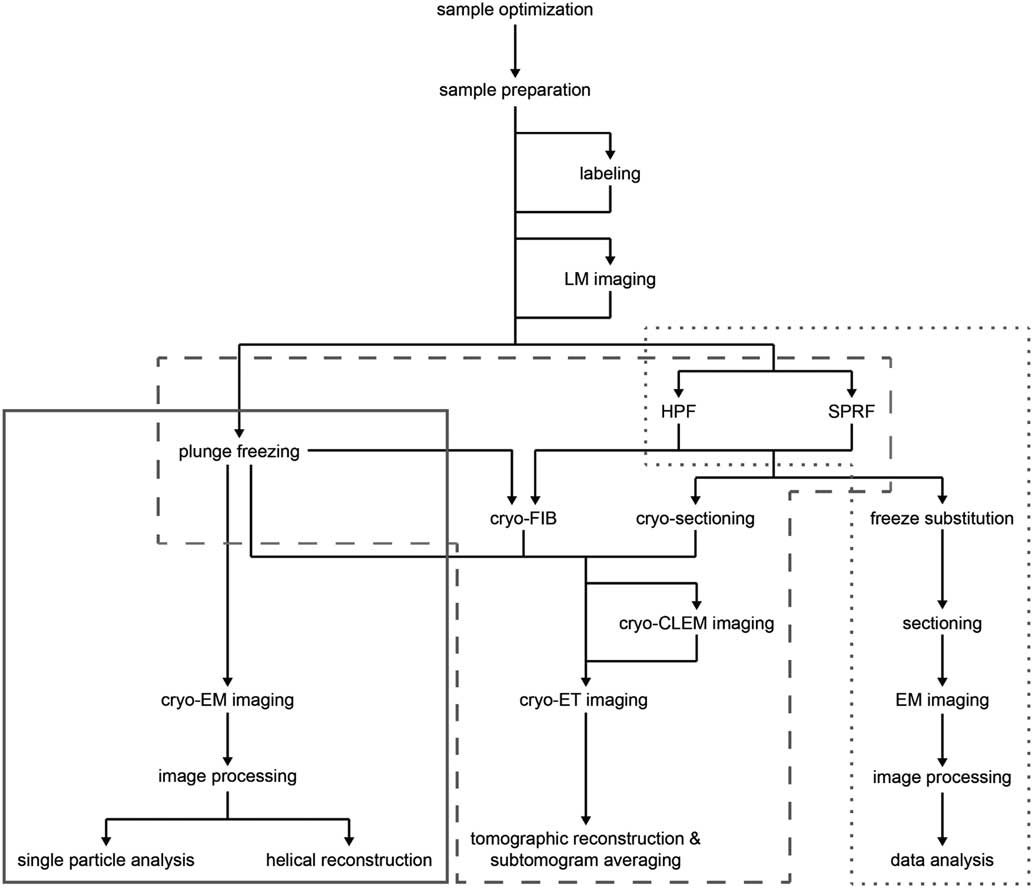
Recent advances in sample preparation, imaging, and data processing have led to a dramatic expansion of cryo-EM in structural biology (Cheng et al., Reference Cheng, Grigorieff, Penczek and Walz2015; Nogales, Reference Nogales2015). The workflow for structure determination by cryo-EM is outlined in Figure 1. Sample optimization is achieved by one of several freezing steps. Vitrification of a thin film sample for SPA cryo-EM or cryo-ET is accomplished by plunge freezing. Larger sample volumes, including confluent cell layers and tissue, may be vitrified using pressure by high pressure freezing (Dahl & Staehelin, Reference Dahl and Staehelin1989; Dubochet, Reference Dubochet1995; Studer et al., Reference Studer, Humbel and Chiquet2008) or self-pressurized rapid freezing (Leunissen & Yi, Reference Leunissen and Yi2009; Han et al., 2012 Reference Han, Huebinger and Grabenbauerb ; Grabenbauer et al., Reference Grabenbauer, Han and Huebinger2014). The sample may be further processed after vitrification by thinning [cryo-focused ion beam milling (cryo-FIB) or cryo-sectioning] or examined by cryo-correlative light and electron microscopy (cryo-CLEM) before cryo-ET imaging and image processing. In this review, we discuss some of the recent advances at various steps of this workflow, which we have used to improve imaging of biological specimens. These include the use of new substrates and methods for sample preparation, phase plates and direct electron detectors for cryo-EM image acquisition, and the application of cryo-CLEM, which combines spatiotemporal information about the sample from fluorescence light microscopy with structural information from cryo-EM. There have, of course, been many other developments in techniques and data processing that are described elsewhere (Bai et al., Reference Bai, McMullan and Scheres2015; Binshtein & Ohi, Reference Binshtein and Ohi2015; Fernandez-Leiro & Scheres, Reference Fernandez-Leiro and Scheres2016; Frank, Reference Frank2017; Murata & Wolf, Reference Murata and Wolf2018).

Figure 1 Cryo-electron microscopy (cryo-EM) workflow. Schematic illustration of options for cryo-EM sample preparation, imaging, and data processing. Solid gray box indicates methods typically used for single particle analysis; dashed gray box indicates methods typically used for cryo-electron tomography (cryo-ET); dotted gray box indicates methods typically used for conventional EM sectioning. LM, light microscopy; HPF, high pressure freezing; SPRF, self-pressurized rapid freezing; FIB, focused ion beam; CLEM, correlated light and electron microscopy.
Substrates and Specimen Preparation
One of the essential components of high-quality, high-resolution cryo-EM is reproducible and robust sample preparation. Cryo-EM samples are typically applied to an EM grid consisting of an amorphous holey carbon film supported by a metal mesh. The grid is then blotted to remove excess liquid and plunge-frozen in a liquid cryogen (“plunge freezing” in Fig. 1), suspending the sample in a layer of vitreous ice. This process preserves the close-to-native-state structure of the hydrated specimen, but can have low throughput and be unpredictable in terms of ice thickness and particle distribution. Additionally, it has been shown that irradiation in the EM leads to deformation of the amorphous carbon, causing sample movement and hence blurred images (Glaeser et al., Reference Glaeser, McMullan, Faruqi and Henderson2011; Brilot et al., Reference Brilot, Chen, Cheng, Pan, Harrison, Potter, Carragher, Henderson and Grigorieff2012; Russo & Passmore, 2016 Reference Russo and Passmoreb ). Recently, several new sample purification methods, substrates, and grid preparation systems have been developed to optimize performance during imaging, including affinity capture systems, gold grids, and advanced vitrification devices.
Cryo-EM single particle reconstructions are based on averaging projections of thousands of identical particles in random orientations (Guo & Jiang, Reference Guo and Jiang2014; Cheng et al., Reference Cheng, Grigorieff, Penczek and Walz2015; Doerr, Reference Doerr2015; Frank, Reference Frank2017). Homogeneity of the sample is therefore extremely important although such purification can be challenging. Cross-linking has been used to stabilize many heterogeneous samples for cryo-EM, such as the proteasome (Lasker et al., Reference Lasker, Forster, Bohn, Walzthoeni, Villa, Unverdorben, Beck, Aebersold, Sali and Baumeister2012), spliceosome (Agafonov et al., Reference Agafonov, Kastner, Dybkov, Hofele, Liu, Urlaub, Luhrmann and Stark2016; Wan et al., Reference Wan, Yan, Bai, Wang, Huang, Wong and Shi2016; Bertram et al., Reference Bertram, Agafonov, Liu, Dybkov, Will, Hartmuth, Urlaub, Kastner, Stark and Luhrmann2017), and membrane complexes (Fiedorczuk et al., Reference Fiedorczuk, Letts, Degliesposti, Kaszuba, Skehel and Sazanov2016; Kosinski et al., Reference Kosinski, Mosalaganti, von Appen, Teimer, DiGuilio, Wan, Bui, Hagen, Briggs, Glavy, Hurt and Beck2016). These studies combined cryo-EM with cross-linking mass spectrometry, which provides even further detail about residues that are in close proximity (Schmidt & Urlaub, Reference Schmidt and Urlaub2017). An additional method for reducing heterogeneity, called GraFix, uses a weak chemical fixation during density gradient centrifugation to provide conformational stability and purify the sample, leading to a more homogenous population (Kastner et al., Reference Kastner, Fischer, Golas, Sander, Dube, Boehringer, Hartmuth, Deckert, Hauer, Wolf, Uchtenhagen, Urlaub, Herzog, Peters, Poerschke, Luhrmann and Stark2008; Stark, Reference Stark2010).
Another concern is preferred orientations of the particles on the grid. Because the sample is confined to a thin layer of vitreous ice, it can interact with both the grid support and the air-water interfaces, leading to a bias in binding and therefore nonisotropic sampling of particle orientations (Stark, Reference Stark2010). Noble et al. have recently shown that ~90% of particles on a typical cryo-EM grid prepared for SPA adsorb to the air–water interfaces, potentially causing preferred particle orientations, conformational changes in the protein, or protein denaturation (Noble et al., Reference Noble, Dandey, Wei, Brasch, Chase, Acharya, Tan, Zhang, Kim, Scapin, Rapp, Eng, Rice, Cheng, Negro, Shapiro, Kwong, Jeruzalmi, des Georges, Potter and Carragher2018). The use of continuous carbon support films to improve particle distribution may provide particular particle orientations, but it may also lead to even more significant orientation problems (Thompson et al., Reference Thompson, Walker, Siebert, Muench and Ranson2016). Self-assembled monolayers (Meyerson et al., Reference Meyerson, Rao, Kumar, Chittori, Banerjee, Pierson, Mayer and Subramaniam2014), poly-L-lysine (Chowdhury et al., Reference Chowdhury, Ketcham, Schroer and Lander2015), and detergents (Zhang et al., Reference Zhang, Ma, DiMaio, Douglas, Joachimiak, Baker, Frydman, Levitt and Chiu2011; Lyumkis et al., Reference Lyumkis, Julien, de Val, Cupo, Potter, Klasse, Burton, Sanders, Moore, Carragher, Wilson and Ward2013), have all been used to reduce preferred orientation, but tend to be sample specific (Tan et al., Reference Tan, Baldwin, Davis, Williamson, Potter, Carragher and Lyumkis2017). The preferred orientation problem may also be addressed at the imaging level, by tilting the specimen during data collection (Tan et al., Reference Tan, Baldwin, Davis, Williamson, Potter, Carragher and Lyumkis2017). Better sampling in Fourier space can be achieved by tilting. However, at high tilts, there is a loss of high-spatial frequency information. Tilting creates a defocus gradient that must be accounted for and corrected. In addition, the ice thickness is increased relative to the electron beam, reducing contrast in the images (Tan et al., Reference Tan, Baldwin, Davis, Williamson, Potter, Carragher and Lyumkis2017).
Single particle cryo-EM of membrane proteins tends to be challenging because the proteins must be extracted from the membrane and solubilized in detergents, which may affect protein structure and function and reduce image contrast (Linke, Reference Linke2009; Baker et al., Reference Baker, Fan and Serysheva2015; Efremov et al., Reference Efremov, Gatsogiannis and Raunser2017). Amphipathic polymers called amphipols are a potential alternative to detergents. These are milder surfactants used to noncovalently bind the transmembrane portion of the protein, improving membrane protein solubility without affecting the contrast of the images. Amphipols have been used in the determination of several membrane protein structures (Flötenmeyer et al., Reference Flötenmeyer, Weiss, Tribet, Popot and Leonard2007; Althoff et al., Reference Althoff, Mills, Popot and Kühlbrandt2011; Cvetkov et al., Reference Cvetkov, Huynh, Cohen and Moiseenkova-Bell2011; Cao et al., Reference Cao, Liao, Cheng and Julius2013; Liao et al., Reference Liao, Cao, Julius and Cheng2013; Lu et al., 2014 Reference Lu, Bai, Ma, Xie, Yan, Sun, Yang, Zhao, Zhou, Scheres and Shia ; Wilkes et al., Reference Wilkes, Madej, Kreuter, Rhinow, Heinz, De Sanctis, Ruppel, Richter, Joos, Grieben, Pike, Huiskonen, Carpenter, Kühlbrandt, Witzgall and Ziegler2017). Another method of preparing membrane proteins for cryo-EM is the use of lipid nanodiscs (Frauenfeld et al., Reference Frauenfeld, Gumbart, van der Sluis, Funes, Gartmann, Beatrix, Mielke, Berninghausen, Becker, Schulten and Beckmann2011; Efremov et al., Reference Efremov, Leitner, Aebersold and Raunser2015; Frauenfeld et al., 2016 Reference Frauenfeld, Löving, Armache, Sonnen, Guettou, Moberg, Zhu, Jegerschöld, Flayhan, Briggs, Garoff, Löw, Cheng and Nordlunda ; Gao et al., Reference Gao, Cao, Julius and Cheng2016; Gatsogiannis et al., Reference Gatsogiannis, Merino, Prumbaum, Roderer, Leidreiter, Meusch and Raunser2016; Matthies et al., Reference Matthies, Dalmas, Borgnia, Dominik, Merk, Rao, Reddy, Islam, Bartesaghi, Perozo and Subramaniam2016; Shen et al., Reference Shen, Yang, DeCaen, Liu, Bulkley, Clapham and Cao2016; Jin et al., Reference Jin, Bulkley, Guo, Zhang, Guo, Huynh, Wu, Meltzer, Cheng, Jan, Jan and Cheng2017). Nanodiscs consist of scaffold proteins surrounding a small lipid bilayer in which the protein of interest is reconstituted. This maintains a near native environment for the protein and provides additional particle size, which may be helpful for particle selection, although heterogeneity of the nanodisc may be a concern (Baker et al., Reference Baker, Fan and Serysheva2015; Efremov et al., Reference Efremov, Gatsogiannis and Raunser2017).
Styrene maleic acid lipid particles (SMALPs) are an alternative to nanodiscs that do not require reconstitution of membrane proteins or detergents at any stage (Hardy et al., Reference Hardy, Bill, Jawhari and Rothnie2016). Styrene maleic acid (SMA) is an amphipathic co-polymer of alternating hydrophobic styrene and hydrophilic maleic acid units, which allows interaction with the membrane and provides solubility for the membrane protein. SMA is able to surround membrane proteins in their native lipids, producing native nanodisc SMALPs, which can then be purified and imaged (Hardy et al., Reference Hardy, Bill, Jawhari and Rothnie2016; Parmar et al., Reference Parmar, Rawson, Scarff, Goldman, Dafforn, Muench and Postis2018). The structure of alternative complex III (ACIII) was recently solved to 3.4 Å using SMA nanodiscs (Sun et al., Reference Sun, Benlekbir, Venkatakrishnan, Wang, Hong, Hosler, Tajkhorshid, Rubinstein and Gennis2018). Yet another method for investigating membrane protein structure uses saposins in complex with lipids and the protein of interest (Salipro, saposin–lipid–protein) (Frauenfeld et al., 2016 Reference Frauenfeld, Löving, Armache, Sonnen, Guettou, Moberg, Zhu, Jegerschöld, Flayhan, Briggs, Garoff, Löw, Cheng and Nordlundb ; Lyons et al., Reference Lyons, Bøggild, Nissen and Frauenfeld2017). Although the process requires the membrane protein to be solubilized in detergent, reconstitution into the Salipro complex is fast and the saposin scaffold can adapt to the size of the transmembrane region of the protein, providing a well-defined complex (Lyons et al., Reference Lyons, Bøggild, Nissen and Frauenfeld2017).
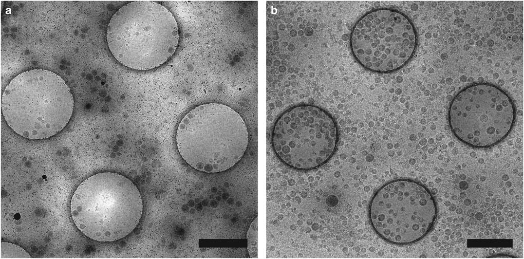
Affinity grids are a new substrate designed to selectively adsorb particles on the EM grid by applying specific affinity between substrate and sample, allowing purification steps to be combined with grid preparation. The grid has a lipid monolayer containing Ni-nitrilotriacetic acid (Ni-NTA) lipids that can recruit polyhistidine tagged (His-tagged) proteins from cell extracts, reducing the required amount of protein and time for purification (Kelly et al., Reference Kelly, Abeyrathne, Dukovski and Walz2008). We have utilized affinity grids with His-tagged Protein A and anti-Env polyclonal antibody to study HIV CD84 virus-like particles (VLPs), resulting in less background and better control of particle density, as shown in Figure 2 (Kiss et al., Reference Kiss, Chen, Brindley, Campbell, Afonso, Ke, Holl, Guerrero-Ferreira, Byrd-Leotis, Steel, Steinhauer, Plemper, Kelly, Spearman and Wright2014). An additional affinity capture method uses 2-dimensional (2D) streptavidin crystals on a lipid monolayer as a nanosupport applied to the EM grid (Wang et al., Reference Wang, Ounjai and Sigworth2008). Biotinylated samples may then bind the streptavidin, improving particle concentration and distribution and reducing preferred particle orientations and the structural consequences of particles binding the carbon film or colliding with the air-water interface of the sample (Wang et al., Reference Wang, Ounjai and Sigworth2008; Han et al., 2012 Reference Han, Walton, Song, Hwu, Stubbs, Yannone, Arbelaez, Dong and Glaesera , Reference Han, Watson, Kang, Pulk, Downing, Cate and Glaeser2016).

Figure 2 Affinity grid designed to selectively capture virus-like particles (VLPs). Cryo-electron microscopy images of HIV CD84 VLPs applied to an untreated grid (a) and a 20% Ni-NTA cryo-affinity grid with His-tagged Protein A and anti-Env polyclonal antibody (b). Use of the affinity capture method leads to increased VLP concentration and improved particle distribution on the grid. See Kiss et al. (Reference Kiss, Chen, Brindley, Campbell, Afonso, Ke, Holl, Guerrero-Ferreira, Byrd-Leotis, Steel, Steinhauer, Plemper, Kelly, Spearman and Wright2014) for experimental detail. Scale bar is 1 μm.
Further developments of the affinity grid include the use of a NTA-polyethylene glycol (PEG) based coating, which combines the anti-fouling properties of brush conformation methoxypolyethylene glycol (methoxy-PEG) with NTA ligands on flexible PEG spacers to prevent preferred orientation of the bound His-tagged proteins (Benjamin et al., Reference Benjamin, Wright, Hyun, Krynski, Yu, Bajaj, Guo, Stauffacher, Jiang and Thompson2016). Another example is a functionalized carbon film with covalently bound Ni-NTA, Protein G, or oligonucleotides to selectively recruit macromolecular complexes (Llaguno et al., Reference Llaguno, Xu, Shi, Huang, Zhang, Liu and Jiang2014). In a simplified affinity grid method, called cryo-solid phase immune electron microscopy (SPIEM), antibodies or Protein A are applied directly to grids, eliminating the need to first apply a lipid monolayer (Yu et al., Reference Yu, Vago, Zhang, Snyder, Yan, Zhang, Benjamin, Jiang, Kuhn, Serwer, Thompson and Jiang2014, 2016 Reference Yu, Li and Jiangb ).
The use of the affinity capture system with silicon nitride (SiN) membrane support films has also shown promising improvements for sample preparation. The hydrophobicity of SiN supports interactions with the lipid tails of the Ni-NTA lipid monolayer, allowing for effective sample capture on the grid. Additionally, the membranes are flat, durable, and can be consistently manufactured, addressing the delicate and inconsistent nature of amorphous carbon supports (Tanner et al., Reference Tanner, Demmart, Dukes, Melanson, McDonald and Kelly2013). Affinity grids combine purification steps with grid preparation, significantly reducing the time required to produce samples for cryo-EM imaging, and can be used for structure determination at high resolution. Yu et al. have recently used the method to determine the structure of a low concentration virus at 2.6 Å resolution (Yu et al., 2016 Reference Yu, Li, Huang, Jiang and Jianga ).
Traditional lacey, Quantifoil (Quantifoil Micro Tools, Jena, Germany), or C-flat (Protochips, Inc., Morrisville, NC, USA) EM grids are made of a metal scaffold (e.g., copper, nickel, or gold) and an amorphous carbon support with holes of various sizes, shapes, and distributions over which the sample is suspended in vitreous ice. Irradiation of amorphous carbon in the EM causes it to bend, however, leading to movement of the sample, often referred to as beam-induced motion, and therefore blurry images. Since the linear thermal expansion coefficient is much lower for carbon than for the metal support, the carbon film may also pucker at cryo-temperatures (Booy & Pawley, Reference Booy and Pawley1993). This can lead to poor imaging and the loss of information at high spatial frequencies. Several alternative substrates have been developed to address these deformations. Titanium–silicon metal glass films, a nanocrystalline silicon carbide substrate called Cryomesh (ProtoChips, Inc.), and hydrogen-plasma treated graphene all decrease beam-induced motion, but do not completely eliminate it (Rhinow & Kuhlbrandt, Reference Rhinow and Kuhlbrandt2008; Yoshioka et al., Reference Yoshioka, Carragher and Potter2010; Russo & Passmore, 2014 Reference Russo and Passmorea ). Ultrastable gold substrates, which consist of a gold foil across a gold mesh grid, are one of the most promising solutions. By using the same material for the support and grid, differential thermal contraction, and therefore puckering during cooling, is prevented and the high conductivity of gold nearly eliminates beam-induced motion, significantly improving image quality (Russo & Passmore, 2014 Reference Russo and Passmoreb , 2016 Reference Russo and Passmorea , 2016 Reference Russo and Passmoreb ).
3D-DNA origami sample supports aim to address many of the current concerns for grid preparation. The sample particles are bound within a hollow support made up of double stranded DNA helices. This helps to control particle orientation, protects particles from the force of blotting with filter paper and from the air–liquid interface, and improves ice thickness consistency. The method was shown to be successful for the DNA binding protein p53, but will require more rigidity to precisely control particle orientation and will need to expand to be more widely applicable to various types of samples (Martin et al., Reference Martin, Bharat, Joerger, Bai, Praetorius, Fersht, Dietz and Scheres2016).
Protein scaffolds are also being used to determine the structures of monomeric proteins that would otherwise be too small for cryo-EM. Coscia et al. have designed a self-assembled symmetric protein scaffold with a small protein genetically fused, producing a large, rigid, and symmetric particle that is more amenable to cryo-EM, and solved the structure at subnanometer resolution (Coscia et al., Reference Coscia, Estrozi, Hans, Malet, Noirclerc-Savoye, Schoehn and Petosa2016). Liu et al. have achieved near atomic resolution of a small protein called DARPin, which is rigidly fused to a self-assembled symmetric protein cage through terminal helices. The amino acid sequence of DARPin can be altered to tightly bind other small proteins, making it widely applicable (Liu et al., Reference Liu, Gonen, Gonen and Yeates2018).
Cryo-EM grid ice should ideally be only slightly thicker than the sample. Excess ice thickness should be avoided because it allows the particles within an image to be at different focal heights and contributes to noise in the images (Glaeser et al., Reference Glaeser, Han, Csencsits, Killilea, Pulk and Cate2016). Conventional blotting with filter paper often leads to inconsistent ice thickness and sample degradation due to the blotting force and it exposes the particles to an air–water interface of the sample. To address these problems, a “self-blotting” grid has been developed to generate reproducibly thin films of ice without the use of a filter paper blotting step (Razinkov et al., Reference Razinkov, Dandey, Wei, Zhang, Melnekoff, Rice, Wigge, Potter and Carragher2016; Wei et al., Reference Wei, Dandey, Zhang, Raczkowski, Rice, Carragher and Potter2018). An ammonium persulfate and sodium hydroxide solution is applied to copper grids, supporting the growth of Cu(OH)2 nanowires on the copper grid bars. The nanowires draw up excess liquid when the sample is applied to the grid, resulting in a thinly spread film of liquid on the grid that is then plunge frozen without the requirement of a blotting step. The self-blotting grids are used in conjunction with a newly designed freezing apparatus called the Spotiton (Jain et al., Reference Jain, Sheehan, Crum, Carragher and Potter2012; Dandey et al., Reference Dandey, Wei, Zhang, Tan, Acharya, Eng, Rice, Kahn, Potter and Carragher2018). This device uses a piezo controlled electric inkjet dispense head to deposit small volumes of sample at defined locations on the grid, which is then plunge frozen. Use of the self-blotting grid with the Spotiton results in thin films of uniform ice and the process is almost entirely automated, increasing the reproducibility and throughput of cryo-EM grid preparation (Jain et al., Reference Jain, Sheehan, Crum, Carragher and Potter2012; Razinkov et al., Reference Razinkov, Dandey, Wei, Zhang, Melnekoff, Rice, Wigge, Potter and Carragher2016; Dandey et al., Reference Dandey, Wei, Zhang, Tan, Acharya, Eng, Rice, Kahn, Potter and Carragher2018; Wei et al., Reference Wei, Dandey, Zhang, Raczkowski, Rice, Carragher and Potter2018).
Another blotless freezing system called the cryoWriter allows real-time monitoring of the water thickness prior to vitrification (Arnold et al., Reference Arnold, Albiez, Bieri, Syntychaki, Adaixo, McLeod, Goldie, Stahlberg and Braun2017). A microcapillary is used to deposit a small sample volume (3–20 nanoliters) onto the grid. Depending on the volume applied, excess sample can either be recovered using the microcapillary or allowed to evaporate. The sample film is evaluated using a laser beam and photodetector and once the appropriate thickness is reached, the grid is plunge frozen. This system prevents the potentially damaging effects of filter paper blotting and uses significantly smaller volumes, allowing the investigation of low abundance samples.
Methods for time resolved imaging, to capture transient states of biological molecules, by mixing reaction components immediately before blotting have also seen recent improvements. This was initially achieved by applying one reaction component to the EM grid in the conventional pipetting and blotting manner to achieve a thin film, then spraying another component onto the film and rapidly freezing (Berriman & Unwin, Reference Berriman and Unwin1994; Unwin, Reference Unwin1995; Walker et al., Reference Walker, Trinick and White1995; Walker et al., Reference Walker, Zhang, Jiang, Trinick and White1999; Berriman & Rosenthal, Reference Berriman and Rosenthal2012; Unwin & Fujiyoshi, Reference Unwin and Fujiyoshi2012). The reaction only proceeds where the components mix, however, potentially leading to heterogeneity in the sample across the grid. This problem was addressed by coupling a micromixer with a microsprayer, allowing external homogenous mixing of the reactants before spraying onto an EM grid and plunge freezing (Lu et al., Reference Lu, Shaikh, Barnard, Meng, Mohamed, Yassin, Mannella, Agrawal, Lu and Wagenknecht2009; Shaikh et al., Reference Shaikh, Yassin, Lu, Barnard, Meng, Lu, Wagenknecht and Agrawal2014; Lu et al., 2014 Reference Lu, Barnard, Shaikh, Meng, Mannella, Yassin, Agrawal, Wagenknecht and Lub ). While this method allows the capture of dynamic processes for cryo-EM imaging, variability in ice thickness and coverage of the grid limits the regions suitable for data collection. The more recent development, by Feng et al., of a polydimethylsiloxane-based microsprayer allows the control of ice thickness through sprayer pressure and distance from the grid, and has the potential to provide time-resolved sample preparation by mixing reactants in a channel for specified amounts of time (Feng et al., Reference Feng, Fu, Kaledhonkar, Jia, Shah, Jin, Liu, Sun, Chen, Grassucci, Ren, Jiang, Frank and Lin2017).
DIRECT ELECTRON DETECTORS
Low electron doses are necessary for the imaging of biological specimens in order to limit radiation damage of the sample. Cryo-EM images are therefore inherently noisy. Additionally, beam-induced motion of the sample leads to blurriness in the images. Both of these issues have been significantly improved by the development of direct electron detectors.
Several types of sensors may be used for the detection of electrons and the performance of the detector is extremely important for achieving high quality data. Detectors can be described by the detective quantum efficiency (DQE), a measure of signal produced from the sample and noise contributed to the image by the detector. A detector that contributes no noise to the image would have a DQE of 1.
Photographic film has historically been used to record cryo-EM images due to its large imaging area and high resolution. Its DQE is ~0.3–0.35 at half Nyquist frequency (McMullan et al., 2009 Reference McMullan, Chen, Henderson and Faruqia , Reference McMullan, Faruqi and Henderson2016). The use of film can be labor intensive and time consuming, however, as it requires development and scanning into a digital format (Faruqi & Henderson, Reference Faruqi and Henderson2007; Binshtein & Ohi, Reference Binshtein and Ohi2015; Thompson et al., Reference Thompson, Walker, Siebert, Muench and Ranson2016). CCD cameras provide a much more automated mode of imaging, allowing for images to be immediately evaluated and for large data sets to be collected quickly. As the electrons hit the detector, a scintillator is used to induce the emission of photons which then hit the CCD. The photons are converted to electrical signals and an electrical charge accumulates. The charge is transferred between neighboring pixels and read out to form a digitized image (Faruqi, Reference Faruqi1998; Sander et al., Reference Sander, Golas and Stark2005; Thompson et al., Reference Thompson, Walker, Siebert, Muench and Ranson2016). The scintillator of a CCD camera produces electron and photon scattering, however, contributing additional noise to the images and leading to a DQE of ~0.07–0.1 at half Nyquist frequency, significantly inferior to that of photographic film (McMullan et al., 2009 Reference McMullan, Chen, Henderson and Faruqia , Reference McMullan, Faruqi and Henderson2016).
Complementary metal-oxide semiconductor (CMOS) detectors are a digital alternative to CCD cameras that immediately convert charge to voltage within each pixel, so they can be operated at a high frame rate (Janesick & Putnam, Reference Janesick and Putnam2003; Cheng et al., Reference Cheng, Grigorieff, Penczek and Walz2015; Faruqi et al., Reference Faruqi, Henderson and McMullan2015). High frame rates provide the ability to fractionate the electron dose of an exposure over multiple frames. This allows the optimal use of electron dose in the image because one can compensate for the loss of high spatial frequency information as the dose accumulates. Frames can then be aligned before summing to correct for beam-induced motion and specimen drift in the image (McMullan et al., Reference McMullan, Faruqi, Clare and Henderson2014).
CMOS-based direct detection devices (DDDs) have radiation hardened sensors that allow electrons to be recorded directly, rather than through a scintillator (McMullan et al., 2009 Reference McMullan, Clark, Turchetta and Faruqib ; Guerrini et al., Reference Guerrini, Turchetta, Hoften, Henderson, McMullan and Faruqi2011; Milazzo et al., Reference Milazzo, Cheng, Moeller, Lyumkis, Jacovetty, Polukas, Ellisman, Xuong, Carragher and Potter2011). This, along with back-thinning, which decreases backscattering of electrons, results in a considerable reduction of noise in the image compared with the noise from electron and photon scattering generated in the scintillator and fiber optics of a CCD (McMullan et al., 2009 Reference McMullan, Faruqi, Henderson, Guerrini, Turchetta, Jacobs and van Hoftenc ). There are several types of DDDs that can be operated in various modes. In integration mode, charge is collected in each pixel, then integrated and read out. The DQE at half Nyquist in integration mode is ~0.4–0.6 (McMullan et al., Reference McMullan, Faruqi and Henderson2016). In counting mode, the signal from each electron event is recorded and weighted the same, which reduces read noise and variability in electron signal. Operating in counting mode while using a high frame rate allows even higher DQEs to be achievable (Li et al., 2013 Reference Li, Mooney, Zheng, Booth, Braunfeld, Gubbens, Agard and Chenga , 2013 Reference Li, Zheng, Egami, Agard and Chengb ). Some cameras may additionally be operated in what is called “super-resolution” mode, in which the electron events are sub-localized within the pixel, surpassing the Nyquist frequency limit (Li et al., 2013 Reference Li, Mooney, Zheng, Booth, Braunfeld, Gubbens, Agard and Chenga , 2013 Reference Li, Zheng, Egami, Agard and Chengb ; Chiu et al., Reference Chiu, Li, Li, Beckett, Brilot, Grigorieff, Agard, Cheng and Walz2015).
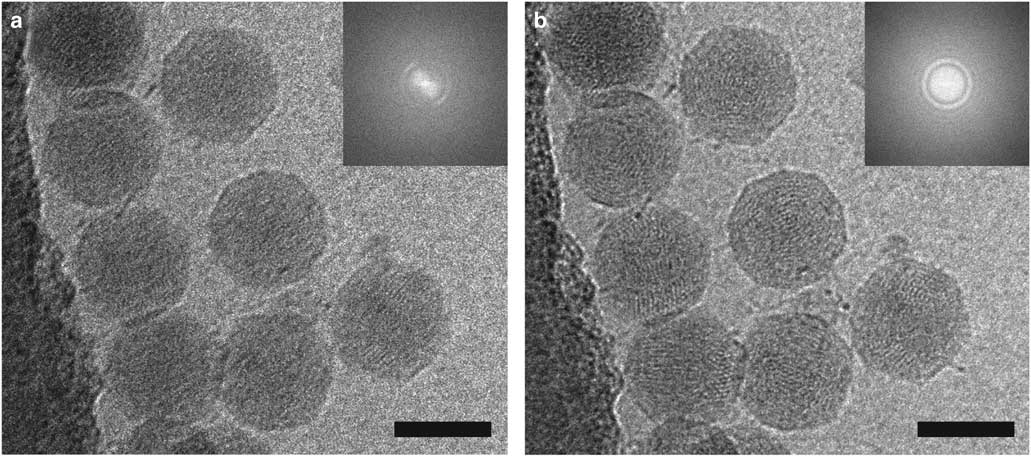
The effects of motion correction can be seen in the image of coliphage BA14 collected on a Direct Electron DE-20 (Direct Electron, LP, San Diego, CA, USA) shown in Figure 3. The image was acquired at 12 frames per second with an exposure time of 5 s and then summed (Fig. 3a) or motion-corrected using scripts from Direct Electron, LP and summed (Fig. 3b). Blurring is significantly reduced by motion correction as shown in the images and power spectra. The ability to combine a high DQE with automation and the implementation of dose compensation and motion correction have led to a dramatic increase in the quality of cryo-EM data and the number of near-atomic to atomic resolution structures being determined (Lu et al., 2014 Reference Lu, Bai, Ma, Xie, Yan, Sun, Yang, Zhao, Zhou, Scheres and Shia ; Parent et al., Reference Parent, Tang, Cardone, Gilcrease, Janssen, Olson, Casjens and Baker2014; Voorhees et al., Reference Voorhees, Fernandez, Scheres and Hegde2014; Bartesaghi et al., Reference Bartesaghi, Merk, Banerjee, Matthies, Wu, Milne and Subramaniam2015; Hesketh et al., Reference Hesketh, Meshcheriakova, Dent, Saxena, Thompson, Cockburn, Lomonossoff and Ranson2015; von der Ecken et al., Reference von der Ecken, Muller, Lehman, Manstein, Penczek and Raunser2015; Merk et al., Reference Merk, Bartesaghi, Banerjee, Falconieri, Rao, Davis, Pragani, Boxer, Earl, Milne and Subramaniam2016).

Figure 3 Motion correction of data recorded on a Direct Electron DE-20 direct electron detection device significantly improves image quality. Two-dimensional (2D) projection cryo-electron microscopy image of coliphage BA14 particles before (a) and after (b) motion correction using Direct Electron, LP scripts and the corresponding power spectra (insets). The image was recorded at a frame rate of 12 frames per second with an exposure time of 5 s. Scale bar is 50 nm.
Despite the improvements in DQE and signal-to-noise ratio provided by direct electron detectors, low contrast in cryo-EM images can still be problematic, particularly for small samples. Additional contrast enhancement, such as through the use of energy filters or phase plates, can be particularly useful in these cases.
PHASE PLATES
The contrast of unstained biological materials is inherently weak under low-electron dose cryo-EM imaging conditions. Contrast can be improved by defocusing of the objective lens, although this results in a reduction of the high spatial frequency components of the image, or with the use of an energy filter, which removes inelastically scattered electrons thereby improving the signal-to-noise ratio (Langmore & Smith, Reference Langmore and Smith1992; Schroder, Reference Schroder1992). Another strategy for addressing low contrast in cryo-EM images is the use of phase plates. We have used two types of phase plates, the thin carbon-film Zernike-style phase plate and the hole-free carbon-film phase plate (HFPP), or Volta phase plate (VPP), although there are additional styles, such as electrostatic (Huang et al., Reference Huang, Wang, Chang, Hwu, Tseng, Kai and Chen2006; Cambie et al., Reference Cambie, Downing, Typke, Glaeser and Jin2007; Majorovits et al., Reference Majorovits, Barton, Schultheiss, Perez-Willard, Gerthsen and Schroder2007; Schultheiss et al., Reference Schultheiss, Zach, Gamm, Dries, Frindt, Schröder and Gerthsen2010; Walter et al., Reference Walter, Muzik, Vieker, Turchanin, Beyer, Golzhauser, Lacher, Steltenkamp, Schmitz, Holik, Kuhlbrandt and Rhinow2012; Frindt et al., Reference Frindt, Oster, Hettler, Gamm, Dieterle, Kowalsky, Gerthsen and Schröder2014) and magnetic phase plates (Edgcombe et al., Reference Edgcombe, Ionescu, Loudon, Blackburn, Kurebayashi and Barnes2012; Blackburn & Loudon, Reference Blackburn and Loudon2014).
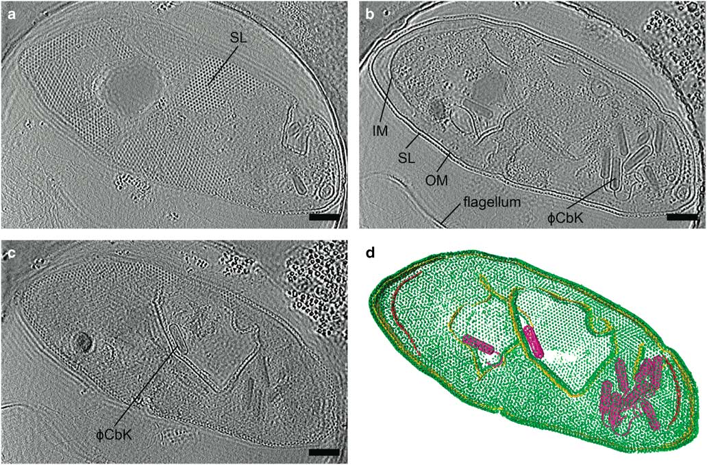
Zernike phase contrast (ZPC) cryo-EM uses a thin carbon film with a small hole, produced by a focused ion beam (FIB), placed in the back focal plane (Danev & Nagayama, Reference Danev and Nagayama2008; Nagayama & Danev, Reference Nagayama and Danev2008; Murata et al., Reference Murata, Liu, Danev, Jakana, Schmid, King, Nagayama and Chiu2010; Schroder, Reference Schroder2015). Unscattered electrons pass through the hole while the scattered electrons go through the carbon film, shifting the phase of the unscattered electrons relative to the scattered electrons by π/2. This changes the contrast transfer function from a sine function to a cosine function (Nagayama, Reference Nagayama2005) and significantly improves the contrast at low spatial frequencies. The images are acquired in focus, eliminating the loss in resolution due to defocusing. The higher contrast provided by phase plates improves image alignment, making it possible for fewer particles to be averaged to produce high resolution structures by SPA (Danev & Nagayama, Reference Danev and Nagayama2008), and providing excellent results for cryo-ET (Danev et al., Reference Danev, Kanamaru, Marko and Nagayama2010; Murata et al., Reference Murata, Liu, Danev, Jakana, Schmid, King, Nagayama and Chiu2010; Guerrero-Ferreira et al., Reference Guerrero-Ferreira, Viollier, Ely, Poindexter, Georgieva, Jensen and Wright2011; Fukuda & Nagayama, Reference Fukuda and Nagayama2012; Dai et al., Reference Dai, Fu, Raytcheva, Flanagan, Khant, Liu, Rochat, Haase-Pettingell, Piret, Ludtke, Nagayama, Schmid, King and Chiu2013). The use of ZPC cryo-EM can be challenging, however, due to a short lifespan, charging, difficulty keeping the phase plate aligned, and fringing artifacts in the images (Danev & Nagayama, Reference Danev and Nagayama2001, Reference Danev and Nagayama2010, Reference Danev and Nagayama2011; Danev et al., Reference Danev, Glaeser and Nagayama2009; Fukuda et al., Reference Fukuda, Fukazawa, Danev, Shigemoto and Nagayama2009; Nagayama, Reference Nagayama2011). Figure 4 and Supplementary Movie 1 illustrate the contrast provided by the Zernike-style phase plate in a tomogram of a Caulobacter crescentus cell infected with bacteriophage ϕCbK, as well as the fringing artifacts.

Figure 4 Zernike phase plate imaging of a phage-lysed bacterial cell provides contrast, revealing internal features. Cryo-electron tomography slices of ϕCbK phage-lysed Caulobacter crescentus cell using ZPC at zero defocus. a: A top slice of the tomogram illustrating the hexagonal surface layer (SL), (b) a central slice revealing newly assembled phages within the lysing cell, and (c) a central slice showing an assembled phage capsid in the process of genome packaging. Fringing artifacts are evident, particularly at the edge of the cell. d: Corresponding three-dimensional segmentation SL, green; OM, outer membrane, gold; IM, inner membrane, red; and ϕCbK, magenta. Scale bar is 200 nm.
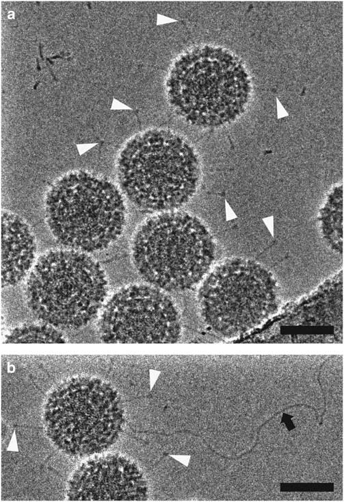
HFPP (or VPP) cryo-EM uses a homogenous carbon film in the back focal plane. Localized irradiation of the carbon film with the electron beam leads to a negative Volta potential, creating a phase shift at the position of the beam and increased contrast in the images (Danev et al., Reference Danev, Buijsse, Khoshouei, Plitzko and Baumeister2014). This form of phase plate has been shown to be more stable for data collection and does not introduce strong fringing artifacts (Danev & Nagayama, Reference Danev and Nagayama2001, Reference Danev and Nagayama2008, Reference Danev and Nagayama2011; Danev et al., Reference Danev, Buijsse, Khoshouei, Plitzko and Baumeister2014; Danev & Baumeister, Reference Danev and Baumeister2016; Khoshouei et al., Reference Khoshouei, Radjainia, Phillips, Gerrard, Mitra, Plitzko, Baumeister and Danev2016). It has recently been used to resolve extraordinary in situ detail via cryo-ET (Asano et al., Reference Asano, Fukuda, Beck, Aufderheide, Forster, Danev and Baumeister2015; Fukuda et al., Reference Fukuda, Laugks, Lucic, Baumeister and Danev2015; Chlanda et al., Reference Chlanda, Mekhedov, Waters, Schwartz, Fischer, Ryham, Cohen, Blank and Zimmerberg2016; Mahamid et al., Reference Mahamid, Pfeffer, Schaffer, Villa, Danev, Cuellar, Forster, Hyman, Plitzko and Baumeister2016; Sharp et al., Reference Sharp, Koster and Gros2016; Khoshouei et al., 2017 Reference Khoshouei, Pfeffer, Baumeister, Forster and Daneva ) and to solve several high-resolution structures via SPA (Chua et al., Reference Chua, Vogirala, Inian, Wong, Nordenskiold, Plitzko, Danev and Sandin2016; Khoshouei et al., Reference Khoshouei, Radjainia, Phillips, Gerrard, Mitra, Plitzko, Baumeister and Danev2016, 2017 Reference Khoshouei, Radjainia, Baumeister and Danevb ; Danev & Baumeister, Reference Danev and Baumeister2017; ). More recently, however, it has been possible to implement a slight defocus with this style of phase plate due to improvements in reconstruction software (Rohou & Grigorieff, Reference Rohou and Grigorieff2015). This lessens the requirement for accuracy in focusing thus increasing the ease of use and the speed of data collection (Danev et al., Reference Danev, Tegunov and Baumeister2017; Liang et al., Reference Liang, Khoshouei, Radjainia, Zhang, Glukhova, Tarrasch, Thal, Furness, Christopoulos, Coudrat, Danev, Baumeister, Miller, Christopoulos, Kobilka, Wootten, Skiniotis and Sexton2017; Khoshouei et al., 2017 Reference Khoshouei, Radjainia, Baumeister and Danevb ). Processing of defocused VPP data has been shown to be either equivalent or more robust than that of defocus phase contrast cryo-EM or in-focus VPP data, by enabling the generation of 3D reconstructions using fewer particles (von Loeffelholz et al., Reference von Loeffelholz, Papai, Danev, Myasnikov, Natchiar, Hazemann, Menetret and Klaholz2018). The use of phase plates continues to present practical challenges, however, and is generally limited to samples that are difficult to visualize without them. In Figure 5, we show 2D projection images of reovirus serotype 1 Lang (T1L) particles collected using HFPP and a slight defocus. The increased contrast allows the viral attachment fibers and released genome to be clearly resolved, without extreme fringing artifacts. Although both ZPC cryo-EM and HFPP cryo-EM provide significantly improved image contrast, the reduced fringing and relative ease of use of HFPP compared to ZPC phase plates will likely make them more widely applicable.

Figure 5 Hole-free phase plate (HFPP) imaging provides enhanced contrast without strong fringing artifacts. Cryo-electron microscopy images of reovirus T1L particles using HFPP slightly underfocus. a,b: Reovirus T1L particles displaying attachment fibers as indicated by white arrowheads. The black arrow points to a released viral genome in b. Scale bar is 50 nm.
Cryo-CLEM
Correlative light and electron microscopy (CLEM or cryo-CLEM) is a technique that combines the spatiotemporal physiological information gained from fluorescence microscopy with the ever-higher resolution of structures from cryo-EM. The technique was developed in response to the absence of methods to unobtrusively label internal cell contents for cryo-EM and has been extremely useful for cellular cryo-ET studies in which localization of cellular components can be difficult in the EM. The fluorescence imaging can be done live or following vitrification of the cells to capture structures in their near-native state (“LM imaging” and “cryo-CLEM imaging,” respectively, in Fig. 1) (Briegel et al., Reference Briegel, Chen, Koster, Plitzko, Schwartz and Jensen2010). This is made possible by the introduction of cryo-cooled stages for the inverted or upright light microscope as well as the integrated light and EM (Sartori et al., Reference Sartori, Gatz, Beck, Rigort, Baumeister and Plitzko2007; Schwartz et al., Reference Schwartz, Sarbash, Ataullakhanov, McIntosh and Nicastro2007; Agronskaia et al., Reference Agronskaia, Valentijn, van Driel, Schneijdenberg, Humbel, van Bergen en Henegouwen, Verkleij, Koster and Gerritsen2008; van Driel et al., Reference van Driel, Valentijn, Valentijn, Koning and Koster2009). Several advantages of cryo-fluorescence microscopy (cryo-fLM) include the absence of morphology-altering fixation, longer fluorophor lifespan (Moerner & Orrit, Reference Moerner and Orrit1999; Schwartz et al., Reference Schwartz, Sarbash, Ataullakhanov, McIntosh and Nicastro2007; Le Gros et al., Reference Le Gros, McDermott, Uchida, Knoechel and Larabell2009), as well as a large field of view (Rigort et al., Reference Rigort, Villa, Bäuerlein, Engel and Plitzko2012; Bykov et al., Reference Bykov, Cortese, Briggs and Bartenschlager2016). This allows regions of interest to be identified quickly without subjecting the sample to a lengthy screening process in the EM, therefore preventing unnecessary irradiation of the sample before imaging. Relocating the region of interest in the EM is facilitated by the use of special finder-style EM grids or commercially available fiducials such as FluoSpheres or TetraSpeck beads (100–200 nm) that are both fluorescent and electron dense (Schellenberger et al., Reference Schellenberger, Kaufmann, Siebert, Hagen, Wodrich and Grunewald2014; Schorb & Briggs, Reference Schorb and Briggs2014). Marker-free alignment methods are also possible, as demonstrated by Anderson et al., in which the centers of the holes in the sample support are used for localization (Anderson et al., Reference Anderson, Page, Swift, Hanein and Volkmann2018).
Samples must be relatively thin in order to be penetrable by the electron beam (less than 1 μm) (Al-Amoudi et al., Reference Al-Amoudi, Chang, Leforestier, McDowall, Salamin, Norlen, Richter, Blanc, Studer and Dubochet2004), but must be even thinner for reliable 3D tomographic reconstruction (~250 nm). This is ideal for cryo-CLEM imaging of viruses (Schorb & Briggs, Reference Schorb and Briggs2014), bacterial cells (Koning et al., Reference Koning, Celler, Willemse, Bos, van Wezel and Koster2014; Daley et al., Reference Daley, Skoglund and Söderström2016), or the thinnest regions of mammalian cells (van Driel et al., Reference van Driel, Valentijn, Valentijn, Koning and Koster2009; Zhang, Reference Zhang2013; Schellenberger et al., Reference Schellenberger, Kaufmann, Siebert, Hagen, Wodrich and Grunewald2014; Carter et al., Reference Carter, Mageswaran, Farino, Mamede, Oikonomou, Hope, Freyberg and Jensen2018). Additional techniques, such as FIB milling to produce thin lamella (Heymann et al., Reference Heymann, Hayles, Gestmann, Giannuzzi, Lich and Subramaniam2006; Marko et al., Reference Marko, Hsieh, Schalek, Frank and Mannella2007; Rigort et al., Reference Rigort, Bauerlein, Leis, Gruska, Hoffmann, Laugks, Bohm, Eibauer, Gnaegi, Baumeister and Plitzko2010; Mahamid et al., Reference Mahamid, Schampers, Persoon, Hyman, Baumeister and Plitzko2015, Reference Mahamid, Pfeffer, Schaffer, Villa, Danev, Cuellar, Forster, Hyman, Plitzko and Baumeister2016; Arnold et al., Reference Arnold, Mahamid, Lucic, de Marco, Fernandez, Laugks, Mayer, Hyman, Anthony, Baumeister and Plitzko2016; Chaikeeratisak et al., Reference Chaikeeratisak, Nguyen, Khanna, Brilot, Erb, Coker, Vavilina, Newton, Buschauer, Pogliano, Villa, Agard and Pogliano2017), or cryo-ultramicrotomy (Al-Amoudi et al., Reference Al-Amoudi, Chang, Leforestier, McDowall, Salamin, Norlen, Richter, Blanc, Studer and Dubochet2004; Bouchet-Marquis & Fakan, Reference Bouchet-Marquis and Fakan2009; Chlanda & Sachse, Reference Chlanda and Sachse2014; Kolovou et al., Reference Kolovou, Schorb, Tarafder, Sachse, Schwab and Santarella-Mellwig2017), however, are required to access the interior of vitrified mammalian cells.
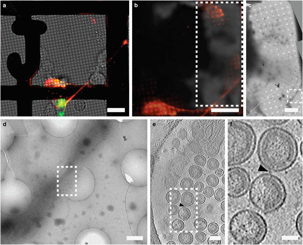
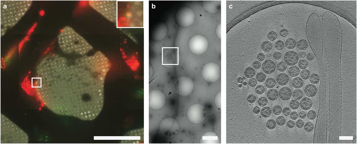
CLEM has been used to visualize the process of virus entry and exit from mammalian cells with great success. Using live-cell fluorescent imaging, cryo-fLM, and cryo-ET, Jun et al. has directly observed pseudo-typed HIV-1 virions with GFP-tagged HIV-1 Vpr interacting with HeLa cells at different time points after infection (Jun et al., Reference Jun, Ke, Debiec, Zhao, Meng, Ambrose, Gibson, Watkins and Zhang2011). Ibiricu et al. used live-cell fluorescence microscopy followed by cryo-ET to identify time points and location of GFP-labeled herpes simplex virus undergoing axonal transport in primary neurons cultured directly on TEM grids (Ibiricu et al., Reference Ibiricu, Huiskonen, Dohner, Bradke, Sodeik and Grunewald2011). To visualize virus after release, Strauss et al. used CLEM procedures to determine the arrangement of mCherry-Gag labeled HIV-1 particles anchored to cell plasma membranes via EGFP-tagged tetherin, a host cellular restriction factor that inhibits enveloped virus release, which can be seen in Figure 6 (Strauss et al., Reference Strauss, Hammonds, Yi, Ding, Spearman and Wright2016). Hampton et al. further investigated these tethered particles using cryo-CLEM, as shown in Figure 7 (Hampton et al., Reference Hampton, Strauss, Ke, Dillard, Hammonds, Alonas, Desai, Marin, Storms, Leon, Melikyan, Santangelo, Spearman and Wright2017).

Figure 6 Correlative light and electron microscopy imaging of transfected mammalian cells provides multi-scale information. HT1080 cells grown on a gold London Finder grid and transfected with EGFP-tetherin (green) and mCherry-Gag (red) were imaged by live cell fluorescence microscopy (a and b), then plunge frozen and imaged by cryo-electron mincroscopy montaging (c and d), and cryo-electron tomography (e and f). The mCherry-Gag (red) signal in a and b corresponds to electron density of a thin cellular extension in c and d. The black arrowheads in e and f indicate a tether attaching two virus-like particles. Dashed boxes correspond to the enlarged image in the next panel. Adapted from Strauss et al. (Reference Strauss, Hammonds, Yi, Ding, Spearman and Wright2016). Scale bar: (a and b) 25 μm, (c) 10 μm, (d) 500 nm, (e) 100 nm, and (f) 50 nm.

Figure 7 Cryo-correlative light and electron microscopy imaging of transfected mammalian cells. HT1080 cells transfected with EGFP-tetherin (green) and mCherry-Gag (red) imaged by cryo-fluorescence microscopy (a), cryo-electron mincroscopy montaging (b), and cryo-electron tomography (c). Dashed boxes correspond to the enlarged image in the next panel. The yellow signal in a (inset) indicates colocalization of EGFP-tetherin (green) and mCherry-Gag (red) signal and corresponds to a cluster of HIV-1 virus-like particles tethered to a cellular extension in b and c. Adapted from Hampton et al. (Reference Hampton, Strauss, Ke, Dillard, Hammonds, Alonas, Desai, Marin, Storms, Leon, Melikyan, Santangelo, Spearman and Wright2017). Scale bar: (a) 50 μm, inset is 3×, (b) 2 μm, (c) 200 nm.
The latest improvements address many of the challenges associated with cryo-CLEM, such as contamination from atmospheric moisture during grid transfer steps, maintaining proper cryogenic temperatures during cryo-fLM imaging, and accurately correlating cryo-fLM and cryo-EM data. Schorb et al. have developed a system that optimizes grid transfer, stage stability, microscope optics, and software, establishing a comprehensive cryo-CLEM workflow (Schorb et al., Reference Schorb, Gaechter, Avinoam, Sieckmann, Clarke, Bebeacua, Bykov, Sonnen, Lihl and Briggs2017). Another system by Li et al. uses a high-vacuum chamber on the fluorescent microscope stage, decreasing contamination of the sample and allowing the objective lens to remain at room temperature. It has additionally been adapted to use a cryo-EM holder, reducing the number of grid transfer steps (Li et al., Reference Li, Ji, Shi, Klausen, Niu, Wang, Huang, Ding, Zhang, Dong, Xu and Sun2018). Future developments in CLEM will expand the use of cryo-super-resolution microscopy to localize specific proteins, further bridging the gap in resolution between light and electron microscopy (Chang et al., Reference Chang, Chen, Tocheva, Treuner-Lange, Löbach, Søgaard-Andersen and Jensen2014; Kaufmann et al., Reference Kaufmann, Schellenberger, Seiradake, Dobbie, Jones, Davis, Hagen and Grünewald2014, Reference Kaufmann, Hagen and Grünewald2016; Liu et al., Reference Liu, Xue, Zhao, Chen, Fan, Gu, Zhang, Zhang, Sun, Huang, Ding, Sun, Ji and Xu2015; Wolf et al., Reference Wolf, Mutsafi, Horowitz, Elbaum and Fass2016).
CONCLUSIONS AND OUTLOOK
Since its development, cryo-EM has played an important role in structural biology and is contributing more and more with recent advances. New developments are broadening the cryo-EM spectrum from whole cells to peptides, allowing more biological questions of greater complexity to be answered and there is still room for improvement.
The timing and capturing of rare and specific events on the macromolecular and cellular levels is now possible using microsprayers and CLEM, respectively, for time-resolved imaging. Reproducibility in the sample preparation and grid preparation processes should continue to improve as grid-based purification methods and the development of vitrification devices such as the Spotiton and cryoWriter mature and expand. Beam-induced motion is being addressed both by the grid substrate and through the use of correction algorithms that utilize the high-frame rate of direct electron detectors.
Advances in electron detection over the past several years have provided remarkable improvements for cryo-EM data collection and quality. Further increasing frame rates, the use of counting mode on all systems, and increased pixel sizes will provide even higher DQEs and super resolution mode should allow direct electron detectors to be used beyond Nyquist frequency (McMullan et al., Reference McMullan, Faruqi and Henderson2016).
While phase plates have shown extraordinary promise for cryo-EM, there are still improvements that can be made. Usage is generally limited to those with expertise (Danev & Nagayama, Reference Danev and Nagayama2008; Glaeser et al., Reference Glaeser, Sassolini, Cambie, Jin, Cabrini, Schmid, Danev, Buijsse, Csencsits, Downing, Larson, Typke and Han2013; Subramaniam et al., Reference Subramaniam, Kuhlbrandt and Henderson2016) and takes a considerable amount of time, so workflow development will be incredibly important for more widespread implementation. Higher reproducibility in the manufacture of phase plates and methods for evaluating phase plate quality during use will also prove to be useful. Phase plates should allow increasingly higher resolution structural work, particularly for small samples, and for entire data sets to be collected more quickly since fewer images will be required.
As CLEM continues to develop, labeling strategies that are retained between live cell and cryo-EM imaging will allow more and more complex biological questions to be addressed and simultaneously fluorescent and electron-dense markers will aid in more precise correlation between light and electron microscopy. Combining cryo-FIB milling of cryo-samples with cryo-CLEM will provide a method for thicker specimens to be investigated and improvements to sample stability between steps of the workflow will help the process become more user-friendly.
The recent developments in cryo-EM imaging, along with improvements in image processing, have allowed tremendous growth in the field over the last few years. We expect this expansion to continue, with cryo-EM providing structures to higher resolutions and answers to increasingly intricate biological questions.
Supplementary material
To view supplementary material for this article, please visit https://doi.org/10.1017/S1431927618012382
Acknowledgments
The authors acknowledge the Robert P. Apkarian Integrated Electron Microscopy Core of Emory University for microscopy services and support. The authors also thank Prof. Xuemin Chen for the HIV-1 VLPs, Prof. Bernardo Mainou for the reovirus T1L preparation, and Prof. Ian Molineux for providing us with coliphage BA14. This work was supported in part by Emory University, Children’s Healthcare of Atlanta, and the Georgia Research Alliance to E.R.W.; the Center for AIDS Research at Emory University (P30 AI050409); the James B. Pendleton Charitable Trust to E.R.W.; public health service grants R01GM104540, R01GM114561, R21AI101775, R01GM104540-03S1 to E.R.W. from the NIH, and NSF grant 0923395 to E.R.W. Public health service grant F32GM112517 to J.D.S. from the NIH.Reovirus data collection at Florida State University was made possible by NIH grants S10 OD018142-01, S10 RR025080-01, and U24 GM116788 to K. A. T.