

Introduction
Mechanical de-icing methods are advantageous because only a comparatively low energy is required to remove ice by a mechanical technique. The energy required to melt even a few millimeters of ice is prodigious because of the latent heat required to convert ice to water (0.33 MJ/kg). For example, the power requirements for the surface area of a small heated radome are estimated to be in excess of 10 kW when the heat losses due to radiation, wind, and temperature during normal operating circumstances are taken into account. In most cases, the power required to de-ice other than very limited surface areas by heating is considered to be prohibitive unless excess heat is available from some other source, or alternative techniques to that of heating are not acceptable. A comparison of the energies required for mechanical and heating methods requires several simplifying assumptions that may not be strictly true, but are helpful in gaining an order-of-magnitude estimate.
For the heating method, we assume that to remove an accumulation from the surface it is sufficient to melt a layer of ice 1 mm thick. (For example, on a vertical surface, gravity would cause an ice accumulation to fall after a layer 1 mm thick at the interface is melted.) The energy required to melt the ice is
where E is the energy, L the latent heat, ρi the density of ice, and V the volume melted (assuming that the ice is at the melting point). For an area of 1 cm2 and a melted thickness of 1 mm2, the energy required is 30.2 J.
For a mechanical estimate, we take the adhesive strength on metals (high adhesive strength) to be 44 N/cm2. Over the 1 cm2 area of the previous example, the force required to displace the piece of ice by (completely shift it from the position it occupies) is 43.1 N
The energy required to displace the ice is the product of this force and the distance moved by the ice (1 cm), i.e.
so that 0.43 J are needed. Thus, the ratio of the energy required to remove ice by heating to the energy required to remove it mechanically is about 70 : 1.
Implicit in this calculation are several simplifying assumptions concerning the melting and breaking processes; these assumptions are subject to different interpretations. However, sophistication in the calculation could not conceivably reduce the ratio by an order-of-magnitude. As an example of the general correctness of this comparison, the current aircraft design standards for melting snow or ice from surfaces specify a delivery of 3–5 W/cm2 of energy to the surface. Typically (Reference Bowden, D. T., A. E. and C. A.Bowden and others, 1964), the power-on time would be of the order of 10 s, which would indicate a need for 30–50 J in order to remove ice by melting. This indicates that our choice of 30 J to remove ice by melting is within the range of current operating practice. Also, the mechanical adhesive strengths used are experimental values generally repeatable (within experimental error) and are frequently cited as reasonable values. If the most favorable calculation from the heating standpoint is taken, it still appears that a ratio of heating energy to mechanical energy of less than 10 to 1 is not easily obtainable.
From this preliminary comparison, one would move to the particular engineering solution desired, and decide whether the problems of delivering either mechanical or heat energy to the desired areas to obtain the desired effect give an advantage to heating methods that outweighs its energetic disadvantages. The whole problem probably cannot be fully resolved without direct comparisons of the two systems in similar operating conditions. However, the preliminary assessment indicates that the potential of mechanical methods justifies pursuing a specific solution to icing problems. An approach to this solution, including field testing of two mechanical de-icing systems, is described in this paper.
I. radome de-icing
Design considerations for a mechanical de-icing system
The principal requirement of an effective system for removing ice is that it shall deliver the energy at the point where it will do the most good. In this case, as is also the case for heating systems, the need is for work to be done at the ice-substrate interface. The most effective method would employ a peeling or scraping action since this requires the least force. However, another method, which requires a slightly greater force, is that of the alternate inflation and deflation of a covering over the radome using compressed air. The pressure is sufficient to fracture the ice on the covering, and the alternate inflation-deflation cycle causes the cover to move out so that the pieces of ice can separate and fall under the influence of gravity. Such a system has the advantage of being relatively cheap, and has standard components (compressor and valves) which a re easy to maintain and have a high reliability. The portion covering the radome (or “boot”) can also be made entirely of dielectric material so that interference with the antenna beam pattern should be minimal.
It was decided, for the geometry of the radome cover, that a quilt or a tube pattern, causing a large radius-of-curvature change to occur over distances equal to the tube width or the spacing of the quilt pattern, would be advantageous. It is evident that with this design many fractures will occur within the ice so that the pieces can be more easily separated, when wind and gravity will carry them away from the covering. Also, the volume of air necessary to inflate the boot will be less since the tube or quilt pattern reduces the thickness of the air space. Another consider ation for the p articular application to radomes is the importance of maintaining a symmetrical shape for the radome. By using a tube or quilt configuration, the relative distortions between different areas of the radome were minimized, and the cylindrical configuration remained substantially intact, since the maximum displacement of the covering from the radome was of the order of a few centimeters.
Calculation of boot pressures necessary to fracture ice
Minimum pressures must be developed within the boot in order to obtain the necessary stresses to fracture the ice. The calculation of this pressure can be performed by using a simple analogy. The boot consists of uniformly spaced, fixed centers which allow no motion of either the boot or the ice covering, i.e. the boundaries between the tubes or the “dots” of the quilt pattern. A constant pressure is applied to the ice in between these fixed points. This problem is equiva lent conceptually to that of a plate (the ice) which is simply supported at equally spaced points and subjected to a constant load. Because of the symmetries of the problem, the solution to an equivalent beam problem would be appropriate. Therefore, we approximate the situation to that of a uniformly loaded beam of ice simply supported at the points where no inflation is allowed to ta ke place, i.e. the boundaries of the tubes or the “dots” of the quilt pattern. We calculate the bending moment M as
where w is the load and l is the distance between successive support points (Fig. 1).

Fig. 1 (left). A model for ice fracture by a pneumatic boot as a simply-supported beam under a uniform load. The supports on the beam are approximated by the immovable area between inflatable tubes and the uniform loading is approximated by the pressure in the boot.
The stress σf necessary to fracture the ice is given by
where b is the ice beam width, h is the ice thickness, S = (bh 2)/6, c is the distance to the neutral axis, and I is the moment of inertia.
Since we are interested in the thickness of ice that can be broken for a given value of the boot pressure, we substitute and rewrite the previous two equations:
Taking b = 1.25 cm, l = 7.5 cm, σf = 1.47 MPa, a table of ice thickness versus boot pressure can be constructed (Table I).
Table I. Calculated values of breakable ice thickness for given boot pressures
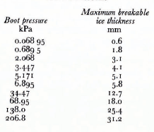
Since the stress used is that appropriate to pure ice with no apparent defects, the ice thicknesses calculated here probably represent lower bounds to those that can be broken in real situations. From this analysis we conclude that a boot pressure of 6.89–399.73 kPa should be adequate to fracture ice provided the inflation cycling time is of the order of minutes, i.e. ice could not build out during one or a few cycles beyond the thickness that can be fractured. Implicit in this analysis is the assumption that the ice will fall away easily if it is fractured. These criteria also assume that an adequate ice detection system will trigger the de-icing system into operation prior to the onset of a heavy build-up. As will be discussed in later sections, these criteria are, and were, obtainable in our tests.
Construction of an inflatable de-icing system
The polyurethane material used in the radome boot was a flexible, black thermoplastic, with an indentation hardness number of 83 on the Shore A scale. The tensile strength was between 40000 and 50000 kPa, with an elongation of 500 to 600%. The fatigue endurance was such that the material could complete 106 cycles before failure. The dielectric constant at 1 MHz was between 6.5 and 7.1. The material could be either heat-sealed or treated with a commercially available solvent in the boot fabrication process.
The final design (Fig. 2) eventually consisted of two layers of 0.3 mm polyurethane film which was used because it was commercially available in wide stock and showed more elasticity than thicker films without an undue loss of strength. This boot had one inflatable layer constructed between the two layers of polyurethane film. The outside seam was continuous and was formed with a heat-sealer soldering iron. The inner connections were dots formed by an iron tip shaped as a circular disc approximately 6.5 mm in diameter. These dot connections proved to be very strong and could withstand the flexing action of the boot.

Fig. 2 (right). The structure of the boot used in the radome covering.
A full-sized cover for a TACAN randome was constructed. This cover had a dot spacing of 75 mm in an equilateral triangle pattern. The bottom edge was a fold in the original spliced sheet, and a drawstring was threaded through this fold to allow tightening around the radome. Two 12.5 mm clear plastic rods were inserted and holes were punched near the rods to give rigidity and to allow a shoe-lacing up the side of the radome. These ties allowed the slack in the material to be taken up and gave the boot a tight fit against the radome. Valves fabricated from “Teflon” were inserted at four locations equally spaced around the bottom of the boot. The use of several valves instead of just one ensured the easy flow and withdrawal of air from all parts of the boot in the event of a fold or small constriction developing at one or more points. Polyurethane tubing connected the four valves on the boot to a manifold located in a frame which also contained the compressor unit and valve control system.
A view of this full-scale cover installed on a TA CAN radome mounted for testing at Mt Washington, New Hampshire is shown in Figure 3. The boot was constructed entirely of dielectric materials, and efforts were also made to maintain the cylindrical symmetry of the radome in its construction. Exceptions to this symmetry were the two plastic rods which were used to provide rigidity at the shoe-lace area. These rods were convenient in fastening the radome of this test boot at the site, and it is believed that an alternative method of fastening the boot together, such as plastic grommets, can be easily devised if necessary to prevent interference with the beam pattern of the antenna.

Fig. 3 (left). A full-sized TACAN radome cover installed on the test site at Mt Washington
A schematic diagram of the inflation system for the de-icer is shown in Figure 4. The operation of the de-icer system was as follows: When the system was energized, either by a single switch or an ice detector, the compressor started and drew the air from the vacuum tank. When the vacuum was low enough, the vacuum control closed and the cycling of valve V2 began. The pressure side of the system was a tank of 0.01 ml volume maintained at approximately 0.28 MPa. The boot held around 0.12 m3 of air at a boot pressure of 13.2 kPa. Any excess pressure was fed back to a relief valve and purged to the atmosphere.

Fig. 4 (right). Diagram of the inflation-deflation cycling equipment used in the 1972–73 winter field tests
The high-pressure control was able to sense a low pressure, to open valve v1, and thus to draw in some air through the vacuum side; this compensated for small leaks in the system. We found it necessary to use a larger tank for the vacuum than for the pressure side. The vacuum needed to deflate the boot totally was approximately 375 mm of mercury. Both the pressure and vacuum were fed to the boot via valve v2. The cycling was controlled by a set of motor-driven cams which were arranged to allow a total inflated time of 30 s and a deflated time of 60 s.
A third cam controlled the cam motor itself to stop the cams so that valve v2 would remain open on the pressure side, and the boot would remain inflated when power to the system was cut.
Field tests if the de-icer system
The field testing program was conducted at the summit of Mt Washington, which is located in the White Mountains in north-eastern New Hampshire. Mt Washington is the highest point in the north-eastern United States of America, and, because of its height, surroundings, and geographical location, has severe weather conditions all year round and particularly severe icing conditions from November to May. These conditions are caused by the interaction of coastal and continental weather systems in this region and the presence of a unique valley structure in the immediate vicinity. The valley structure is such that a pronounced orographic uplift exists, leading to the presence of a cloud cap during most of the year. Under winter conditions, the fog in this cloud cap deposits supercooled water droplets on any surface it strikes, leading to heavy ice formations.
The summit is also convenient for testing since people are stationed there throughout the year. In addition to people maintaining transmission and relay equipment for 'television and radio communications, there is an independently run first-order weather station, the Mt Washington Observatory. The observatory has two full-time weather observers who were contracted to activate and monitor the de-icing experiments. Accurate weather summaries, photographic coverage of the de-icing tests, and narrative descriptions of the de-icer operation were provided for the two seasons of tests, the winters of 1971–72 and 1972–73. Trips to the summit were made at scheduled intervals by chartered “Snow Cat” for the purposes of maintenance, testing, and conference activities.
The test site at the summit was close to the building which housed the observatory, it was at the end of an elevated track used by a cog-railway excursion train during the summer season. A TACAN radome was mounted on a platform on this track at a base height approximately 2.1 m above the ground. The platform was attached by spikes and was also guyed to the railway trestle for protection against winds. A small shack was constructed under the tracks directly below the radome to house the compressor, tanks, valves, and other components of the inflation system. Power was supplied to the shack through a line from the observatory building, approximately 7.5 m away.
Results and conclusions from the 1972–73 winter tests
The 1972–73 season was devoted to a test of the full-sized radome cover of the quilt design described earlier and shown in Figure 3. A number of features were incorporated into the final system in order to protect it against the damage suffered by some of the test strips in the previous winter, and also to take full advantage of the wind forces available for removing ice. This was accomplished by constructing the top portion of the cover to fit under the top cover of the TACAN radome (on the non-vertical faces this portion was not inflatable) to provide a tight fit and to prevent loose ends being ripped by the wind. The inflation system was also designed to dump air from the tank into the boot when the system was shut down, leaving the boot in a partially inflated condition. The boot could then be moved slightly by the wind and hopefully the “fluttering” action would act as a passive de-icer, allowing small accumulations of ice to be easily removed while they were forming. It was also believed that wind action would remove any residual ice left after the de-icer was shut down, if it was partially inflated.
Tests during the first half of the season indicated that the de-icer had the ability to accomplish two objectives : (I) It appeared that partial inflation of the de-icer was successful in removing light accumulations of ice under the action of strong winds alone. Heavy icing conditions negated this effect, but, if the rate of icing was sufficiently low, the boot would successfully remove ice that would have remained on more static structures. (2) The boot could also remove successfully from the radome extensive accumulations that consisted largely of a glaze of denser rime. Figures 5 and 6 show the sequence of de-icing from the start of the inflation equipment. In both cases the time for a substantial clearance of ice was about 10 min, or roughly four inflation–deflation cycles.

Fig. 5. Photographs showing the progress of de-icer action from the beginning of the operation (a). The time span a–d is 10 min.

Fig. 6. Another example of de-icer action. The time span a–d is approximately 10 min.
During the second half of the season a Rosemount Ice Detector was used to activate the de-icer system instead of manual activation. The detector was arranged to start the de-icer when an icing signal was received. The ice detector triggered the timer and shut off the de-icer approximately 15 min after the last icing signal was received.
The results were as follows: (1) The activation of the de-icer by the ice detector was successful since it started the equipment only when an icing condition occurred. The system broke down only during the early stages of the testing, when an unstable mounting on the ice detector caused damage to its probe and rendered it ineffective. When the detector was repaired, the system performed satisfactorily in its activation for a three-month period. (2) The use of the ice detector in the system allowed the de-icer to keep accumulation at minimal levels and it appeared that it would have kept a real system operative most of the time. The system was able to clear the build-up of ice for most conditions. Continued wind action, solar heating on the black surface, and sublimation also assisted in removing any residual ice which accumulated intermittently on the radome and which was not removed during the original de-icing period. Figure 7 shows two examples where the surrounding structures underwent severe icing whilst the radome surface remained clear of ice during a long-term icing condition.

Fig. 7. Photographs of the Mt Washington site. Note that no heavy ice build-up has occurred on the radome cover.
From these tests, it is concluded that the de-icer-ice-detection system using an inflatable de-icer and an ice detector would help considerably in keeping radar sites operational when snow and ice accumulations would normally cause a breakdown or signal distortion.
II. Lock wall de-icing
Lock walls in ship navigation locks represent a quite different de-icing problem to that of radomes since the ice accumulations result from hydraulic rather than atmospheric conditions. The build-up occurs because of two major factors. First, the ice is brought in with ships from up-stream during the locking process. This ice is crushed against the walls and gates by the moving vessel. In below-freezing air temperatures the ice will freeze and remain on the walls. This build-up is very rapid, for example 0.25 m of ice can accumulate during a single ship passage.
The second factor is the rise and fall of water levels during lock operations in below-freezing air temperatures. Each time the level is changed, some water remains and freezes to the wall. The accumulation rate depends on the number of lock operations as well as the air and water temperature, and is relatively slow compared with the rate due to the crushing of ice on the wall, but over a period of time this second type of accumulation may also become a serious problem.
Since inflatable de-icers were successful on radomes, this approach was again utilized. Inflatable devices offer several advantages over other methods. Some of these advantages are: a readily available driving media (compressed air), which is already installed at most sites; standard fabrication processes, high strength and durability; and relatively low overall system cost. The energy required to crack ice is so much lower than to melt even a very thin layer that operational costs could also be expected to be lower than for a heating system. In the application of these ideas to lock walls and gates, two problems which had to be considered were the ability of the de-icer to remove thick accumulated ice and the durability of the de-icer to withstand the forces which ships could apply to it either directly, or indirectly through the crushing ice.
Although more complex conditions may control the effectiveness under real conditions, calculations of the forces required for ice separation or fracture based on the following assumptions and criteria for the transition give us some insight into the process of ice removal by this system.
Let us assume that the de-icer consists of a pair of rigid plates hinged at both ends which can be opened slightly by some means (such as a pneumatic method). Three modes of ice removal, which depend upon the thickness of the ice built up on the plate, can be identified as shown schematically in Figure 8. The force required for ice removal and the transition points can be calculated using the equations given below. Assuming the various strengths of ice and the adhesive strength of the ice–steel system:
Condition (a) Ice is thin so that it is fractured at the hinges, but little ice is removed.
Condition (b) Ice will be fractured in the intermediate thickness range, then separated by shear action.
Condition (c) Ice cannot be broken when it is thick, but simply separated from the plate by tensile force aided by peeling action.
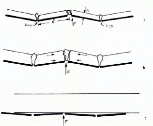
Fig. 8. Models of ice removal for different thicknesses of cover. a. thin ice, b. intermediate thickness, c. thick ice.
For the thinnest ice (Fig. 8a) the force F needed for ice removal is given by
where h is the ice thickness, l is the distance between fracture points, d is the width of the ice accumulation (not shown in these Figures) and T is the tensile strength of the ice (250 N/cm2). The force needed for the removal of intermediate thicknesses of ice is given by (Fig. 8b)
where S s is the shear adhesive strength of the ice (55 N/cm2).
The transition from mode (a) to (b) would occur when
where C is the compressive strength of ice (400 N/cm2), i.e. at the ice thickness 0.1375l (where l ≃ 300 mm in the present case) so that ice would begin to be sheared off when its thickness exceeds 41.25 mm. The force needed for the removal of thick ice (Fig. 8c) is given by
where T a is the tensile adhesive strength (350 N/cm2). The transition from mode (b) to (c) would occur when either

or

in other words, at 1.18l = 354 mm. Laboratory experience indicated that this estimation predicted these transitions reasonably. The force required for separation in case (b), however, is several times smaller than the calculated value. Uneven stresses applied on the ice panel interface due to uneven thickness of ice probably caused the initiation of a crack at the edge of the ice, and then the crack spread with a very small supply of energy.
De-icer design and construction
The final design allowed for expansion of the de-icing surface and provided some resistance to the heavy abrasion likely to be caused by vessels in the locks. The outer surface material consisted of two steel plates backed with a sheet of cast rubber. A hose (100 mm diameter) of the type used for firehose was behind the rubber along the center line connecting the steel plates which were hinged in the center. A de-icer plate installed on a lock wall is shown in Figure 9. As shown, the outer plates were fastened to steel pipes mounted on the lock wall and could rotate when the firehose was inflated.

Fig. 9. Model II de-icer installed in the cold pit area and attached to steel pipes mounted all the lock wall.
A series of five de-icer plates were installed along a section of lock wall at Sault SainteMarie, Michigan, during a winter season. Figures l0a and b are diagrams of the installed design in the inflated (a) and deflated (b) condition. Air pressure of 0.55 MPa was used to inflate the de-icer. Figure 10c shows the installed section of lock wall de-icer after a de-icing test which demonstrated the removal of a sheet of ice over two-thirds the length of the de-icer (≈ 1.75 m) and the entire width of the working section. The ice thickness varied over the length but was about 300 mm in the thickest region. Two cycles (2 inflation–deflations) were required to remove the ice.

Fig. 10. a and b. Diagram if the de-icer installed for field testing at Sault Sainte-Marie, Michigan. c. Photograph of the test de-icer. Note the ice already removed in the region of the de-icer; this removal needed no more than three to four inflations of the system.
The major problems for installing such a system appears to be its very high initial cost and its durability which was not adequately tested over only one season. It does, however, remove ice (as some methods do not!) and does so in a very short time. The frequent and rapid ice removal could be a distinct economic advantage over other systems since considerable savings could be made if the delay time to ships waiting for locks to become operational can be reduced. A single iron-ore carrier, for example, would be expected to lose many thousands of dollars for each day of delay if it could not pass through a lock because of ice blockage problems.
Discussion
D. Kuriowa: I suspect that the surface of your de-icing device may be destroyed by weathering. Could you tell me how long the de-icing action would remain effective during the winter?
S. F. Ackley: The boot lasted well throughout the entire winter session with little evidence of deterioration at the end. It was also subjected to some laboratory tests later without effects of noticeable deterioration appearing. I would guess that it would last several years on an installation before replacement. It is also cheap and easily constructed, so replacement of the original cover could easily be made as a normal maintenance operation at the installation during good weather.
E. Vittoratos: Why is the cost of the mechanical system prohibitive?
Ackley: The area of lock wall is several thousand square metres and the steel needed for protecting the inflation portion of the de-icer would be quite expensive compared to methods that do not need protection (chemical coatings) or are not installed on the wall (jet cutting or chain-saw methods).


