
Introduction
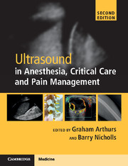
Airway management is one of the most important skills for anesthesiologists. The traditional approach, based on knowledge of regional anatomy and training on patients, is routinely applied with variable results in terms of accuracy of evaluations, implementation of a maneuver and its check, and management in emergency situations. Such an approach cannot entirely consider factors associated with individual variability. Nowadays, airway management can be significantly improved by applying ultrasonography, whether in the operating room, the intensive care unit (ICU), or the emergency department [Reference Kundra, Mishra and Ramesh1]. Amongst imaging tools, ultrasonography is the most suitable in this field as it is fast and relatively easy to perform, available in all centers, pain-free, safe, reasonably priced, and can be reproduced by skilled operators [Reference Sustic2]. It provides information regarding all of the upper airway (supraglottic, glottis, and subglottic regions) [Reference Chan3] (Figure 7.1*).
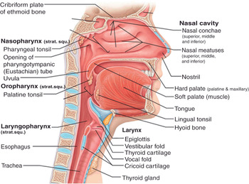
Figure 7.1* Sagittal section of the respiratory tract. It is divided into two main parts, the upper and the lower respiratory tract (or airways), referring to the carina as a landmark. In the field of airway management, upper airways are further divided into three parts: supraglottic, glottis, and subglottic regions. The supraglottic region includes nasal cavity, palate, mouth, tongue, epiglottis, hyoid bone, hyothyroid membrane, and naso- and oropharynx. The glottic region consists of laryngeal aditus, vocal cords (true and false), arytenoid and thyroid cartilages, and laryngopharynx. The subglottic region includes cricothyroid membrane, cricoid cartilage, and trachea. The cuff of an endotracheal (ETT) or a tracheostomy tube is usually detectable above the carina (not shown in the picture).
The use of ultrasound (US) imaging makes evaluations and the implementation of any airway intervention more precise and reliable. Scientific studies on the application of US in airway management have been developed over the last years, in conjunction with the widespread availability of inexpensive and portable US machines. An intervention can be performed, or information on airways can be obtained, in real time and with no need for consulting other healthcare professionals, such as radiologists; this is especially helpful for rapid decision making in emergency situations. To obtain the maximum advantage, it has been observed that ultrasonography should be dynamically applied during all phases of procedures concerning airways (i.e., before, during, and after each phase) [Reference Kristensen4].
Therefore, airway management can be improved by combining personal skills and ultrasonography [Reference Kajekar, Mendonca and Gaur5].
Equipment and technical issues
Ultrasounds are acoustic waves characterized by a frequency above the threshold of human detection (above 20 000 Hz) [Reference Hatfield and Bodenham6]. In the field of medical imaging, frequencies ranging from 2 to 15 MHz are routinely used [Reference Kristensen4]. US probes contain piezoelectric materials whose mechanical and electrical properties result in the production and transmission of sound waves, and their reception in the form of echoes from tissues. According to the pattern of reflection of the received sound waves, which depends upon the different impedance of each tissue to ultrasound, the transducers recreate the shape and the internal structure of the explored organs [Reference Kundra, Mishra and Ramesh1,Reference Hatfield and Bodenham6]. In the presence of different acoustic interfaces, the majority of echoes are derived from tissues shown as white and called hyperechoic [Reference Kristensen4]. In the presence of few acoustic interfaces, echoes are formed much less; the structures appear black and are called hypoechoic [Reference Kristensen4]. An inverse relationship exists between the US frequency and its ability to penetrate into tissues (e.g., low frequency and high penetration into tissues), and there is a direct relationship between frequency and potential image resolution [Reference Kundra, Mishra and Ramesh1,Reference Hatfield and Bodenham6]. When examining airways, superficial structures (2–3 cm below the skin) are visualized with 7.5 MHz linear probes, and deep structures with 5 MHz curved-array probes [Reference Kundra, Mishra and Ramesh1,Reference Singh, Chin and Chan7]. Airways are mostly superficial structures, but their content of air prevents their deeper parts from being properly visualized [Reference Kundra, Mishra and Ramesh1]. Similarly, the presence of air inside the filled cuff of an endotracheal tube makes its visualization impossible. Air is a weak conductor of US; at the tissue–air interface ultrasounds are reflected and artifacts created (Figure 7.2*). For this reason, transducers with variable frequencies should be used, along with cross-beam imaging, in order to obtain images of good quality [Reference Kajekar, Mendonca and Gaur5], or it may be necessary to adopt tricks to optimize the US reflection pattern, e.g., filling the cuff of an endotracheal tube with fluids (e.g., saline) [Reference Kundra, Mishra and Ramesh1] or air bubbles, or visualizing the tube during its passage through the larynx.
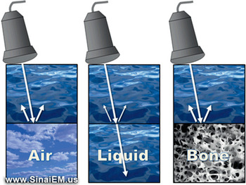
Figure 7.2* Effect of air and bone on ultrasound images. Air has minimal acoustic impedance; at the tissue–air interface, US waves are reflected, leading to the creation of a reverberation artifact of the structures beyond it. Bone has a high acoustic impedance, producing a strong US echo at the tissue–bone interface, which prevents visualization of the structures beyond it. The bony structure appears hyperechoic (white) and the structures behind it appear anechoic (black), a phenomenon known as “acoustic shadowing” (no echoes). Most tissues, which have a certain content of fluid, create acoustic interfaces which allow the US beam to reach the tissues; a variable proportion of the US beam is reflected, depending on the acoustic impedance, and this makes the ultrasound visualization of those tissues possible.
A basic evaluation of the airway can be performed by using three scanning planes of a transcutaneous approach: transverse, sagittal, and parasagittal, considering the anterior midline of the extended neck as a landmark. Through these planes the oral cavity and the frontal and lateral walls of pharynx, larynx, and upper trachea are visualized [Reference Sustic2,Reference Kajekar, Mendonca and Gaur5]. The bone impairs US images as well because of its high acoustic impedance; at the tissue–bone interface ultrasound is strongly reflected, preventing the reflection of US from whatever is beyond it and, as a consequence, nothing is visualized (acoustic shadowing) (Figure 7.2*). For example, the hyoid bone “hides” the epiglottis and the posterior part of the airway, and the rami of the mandible hide the lateral muscles of the mouth floor. We can see the part of the epiglottis below and above the hyoid, but the visualization of the part behind it can be challenging [Reference Kajekar, Mendonca and Gaur5]. It has been suggested that the use of parasagittal scanning through the hyothyroid window improves visualization of the epiglottis, minimizing the effects of air and bone [Reference Prasad, Singh and Chan8]. It has also been reported that sublingual scanning is able to provide different images for a different spatial approach. The curved-array probe is placed in the sublingual fossa and delivers a high frequency (8 MHz). The resulting images derive from a better contact of tissues with the probe [Reference Tsui and Hui9]. The two transcutaneous and sublingual approaches can give complementary information and make the evaluation more accurate.
Several modes of US imaging exist, including A-mode, B-mode, M-mode, and Doppler mode [Reference Hatfield and Bodenham6]. In the field of airway management, the last three are most important. B-mode ultrasonography provides static images with two dimensions (2D); M-mode presents B-mode images in a rapid sequence, producing the visualization of movements; Doppler mode visualizes structures in B-mode, providing information derived from velocity [Reference Kristensen4]: for example, the features of the flow in a vessel.
Principles of sonoanatomy of the upper airways
Ultrasonography is a reliable tool for the examination of airways, based on a study which compared the measurement of eight parameters related to airways in volunteers by US and computed tomography (CT) [Reference Prasad, Yu and Wong10]. The analyzed parameters were: distance to posterior surface of the tongue, thickness of the submental region, hyomental distance, thyrohyoid distance, depth of the epiglottis above and below the hyoid bone, depth of the arytenoid cartilage from skin, and thickness of the fat pad at the thyroid cartilage level (Figure 7.3). No statistical difference between the two techniques was found in five out of the eight parameters measured. The three parameters with a significantly different measurement were: hyomental distance, depth of epiglottis above the hyoid bone, and thickness of fat pad at thyroid cartilage. The reasons for the differences found were: inter-subject variability in the position of the hyoid bone, insufficient extension of the neck of the participants, and variability in the pressure related to the probe applied to the skin [Reference Prasad, Yu and Wong10]. For US examination of airways, the patient should be placed supine with the head in the sniffing position and a pillow under the occiput in order to maximize the extension of the neck [Reference Kundra, Mishra and Ramesh1].
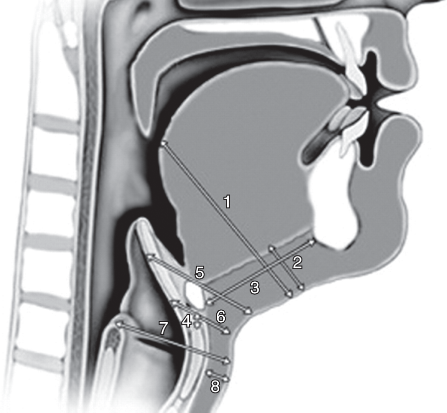
Figure 7.3 Parameters related to airways. (1) Distance to posterior surface of the tongue at the level of the soft palate, (2) thickness of the submental region, (3) hyomental distance, (4) thyrohyoid distance, depth of the epiglottis (5) above and (6) below the hyoid bone, (7) depth of the arytenoid cartilage from the skin, (8) thickness of the fat pad at the thyroid cartilage level. Ultrasonography is a reliable tool to measure such parameters. These measurements quantitatively express some morphologic features of the head and the neck. Modifications of one or more parameter can lead to a reduced laryngoscopic view and difficult intubation, following a specific pattern for each one (see Table 7.2). By combining the obtained information it is possible to predict the degree of difficulty of intubation.
The hyoid bone is an important landmark for the sonoanatomy of the upper airways, which can be divided into two scanning planes called the suprahyoid and infrahyoid regions [Reference Singh, Chin and Chan7] (Figure 7.4*). The hyoid bone can be visualized in transverse, sagittal, and parasagittal scanning, as a superficial hyperechoic structure with a posterior acoustic shadow [Reference Singh, Chin and Chan7].
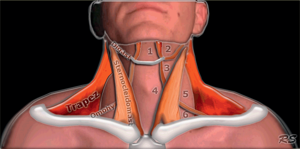
Figure 7.4* Anatomy of the neck. The hyoid bone is a landmark which separates the neck into two scanning areas, the suprahyoid and infrahyoid regions. Each region has its own anatomic features and US appearance, and it is possible to determine morphometric diameters relevant to airway management in each one.
Suprahyoid structures are studied using a curved, low-frequency probe in order to visualize deep structures in a wide field of view. The floor of the mouth is composed of muscles, mainly the mylohyoid, geniohyoid, and genioglossus muscles, going from the most superficial to deepest; they appear as hypoechoic curved stripes on a transverse view and as linear stripes on a sagittal view [Reference Singh, Chin and Chan7] (Figure 7.5). The tongue is attached to the deep muscles of the mouth floor and its dorsal border is characterized by a hyperechoic profile based on an air–mucosa (A–M) interface. The presence of the intrinsic muscles gives a striated appearance on US [Reference Singh, Chin and Chan7] (Figure 7.5). Three-dimensional ultrasonography is helpful to study the tongue in detail. The palate can be visualized if the tongue is adherent to it; if not, it is not possible because of the presence of air. The presence of water in the mouth improves the visualization of the palate and could help to differentiate between the soft and hard palate [Reference Kristensen4].
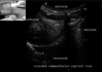
Figure 7.5 Submandibular sagittal view. E, epiglottis; GH, geniohyoid; H, hyoid; MH, milohyoid; P, palate; PES, pre-epiglottic space; SLF, sublingual fossa; T, tongue; TC, thyroid cartilage. Note the A–M interface on the surface of the tongue.
The infrahyoid region can be studied using both low- and high-frequency probes. The thyrohyoid membrane provides a window for the visualization of the epiglottis, in both transverse and parasagittal views. Superior laryngeal nerves, passing through it, can be visualized as well [Reference Singh, Chin and Chan7]. The epiglottis appears as a curved, hypoechoic, and linear structure surrounded by a hyperechoic pre-epiglottic space anteriorly and a linear A–M interface posteriorly [Reference Singh, Chin and Chan7,Reference Werner, Jones and Emerman11] (Figure 7.5). The exposure of the tongue and swallowing improve the visualization of the epiglottis, as it moves away from the acoustic shadow of the hyoid bone [Reference Singh, Chin and Chan7]. The US-estimated thickness of the epiglottis was found to be 2.39 mm on average, and no significant correlation was found with height, considering men and women separately [Reference Werner, Jones and Emerman11]. The cartilages of the larynx and trachea generally appear hypoechoic; however, their US appearance may become hyperechoic due to calcification, variable in its extent over time [Reference Kristensen4]. The thyroid cartilage is detectable either in the sagittal and parasagittal scan as a hypoechoic line with an A–M interface behind, or in the transverse scan as an inverted V with the false vocal cords in the middle [Reference Singh, Chin and Chan7]. Vocal cords are best visualized through the window provided by the thyroid cartilage. If the thyroid cartilage is calcified, vocal cords can be visualized by combining two scans: one is performed cranial to the superior thyroid notch, and the other through the cricothyroid membrane, both in the midline and in each part of it, keeping the probe angled cranially at 30 degrees [Reference Kristensen4]. The true vocal cords appear as two hypoechoic triangles, with the hyperechoic vocal ligaments medial and in the same plane; the false vocal cords appear hyperechoic and are superior to the true ones, and appear fixed during phonation [Reference Singh, Chin and Chan7] (Figure 7.6*). Vocal cord movements are best imaged with 3D ultrasonography [Reference Kundra, Mishra and Ramesh1]. The cricoid cartilage appears hypoechoic and can be visualized in both transverse and sagittal scans. The presence of air creates a hyperechoic A–M interface and artifacts on its posterior side [Reference Singh, Chin and Chan7]. Between the thyroid and cricoid cartilages there is the cricothyroid membrane, which appears as a hyperechoic band linking the two cartilages, in sagittal and parasagittal views [Reference Singh, Chin and Chan7].
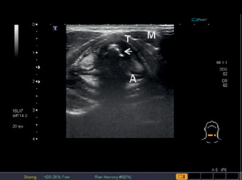
Figure 7.6* Transverse US view of the larynx at the level of the vocal cords. Note the true vocal cords (hypoechoic) (arrow), the false ones (hyperechoic), strap muscles (M), and arytenoid (A) and thyroid (T) cartilages.
Tracheal rings appear hypoechoic and present an A–M interface and reverberation artifacts on the posterior surface. They have the shape of a “string of beads” in both sagittal and parasagittal views, and a U-shape in the transverse view [Reference Singh, Chin and Chan7]. The esophagus should be identified posterior and lateral to the trachea, at the height of the suprasternal notch in a transverse view. The visualization can be improved by swallowing, due to the detection of peristalsis [Reference Singh, Chin and Chan7] and by positioning the neck slightly flexed and turned 45 degrees, performing the exam on the opposite side [Reference Kristensen4].
The knowledge of airway sonoanatomy is an essential requirement when searching for possible abnormalities and performing morphologic measurements (Table 7.1); these elements are clinically useful in the prediction of difficult intubation.
| Suprahyoid region | Infrahyoid region | |
|---|---|---|
| US probe |
|
|
| Anatomic structures |
|
|
| Diameters measurable by US |
|
|
The detection of the anatomic structures in both regions (supra- and infrahyoid) allows for the detection of abnormalities. Such structures represent landmarks for the measurements of diameters useful for pre-intubation assessment. The patient should be supine with extended neck, and each region should be studied with the appropriate probe.
Applications of sonography to airway management
The applications of sonography to airway management are various, and have been developed mainly during the last few years. They can be divided into three broad groups: intubation, tracheostomy, and other applications.
Intubation
Endotracheal intubation is an essential technique to ensure the patency of airways, in the operating room, ICU, emergency department, and in the prehospital setting. Thus, it is not only anesthesiologists who should acquire competency in this field. Each professional may have a different background which can be refined by the use of ultrasonography. Ultrasound information can be transmitted, facilitating communication among professionals. Endotracheal intubation encompasses a pre-procedural evaluation and the confirmation of tube placement.
Pre-intubation assessment
Traditionally, clinical elements such as a modified Mallampati score of 3 or 4, thyromental distance < 6 cm, mouth opening < 4 cm, or limited mobility of the neck are known to be associated with difficult intubation. It has been demonstrated that they are poor predictors of difficult intubation in obese [Reference Ezri, Gewurtz and Sessler14] and non-obese patients [Reference Adhikari, Zeger and Schmier12], and there is no correlation between clinical tests and US-derived measurements [Reference Adhikari, Zeger and Schmier12]. The thickness of the pretracheal soft tissue at the level of vocal cords determined by ultrasonography (28 mm on average) is associated with difficult intubation in obese patients [Reference Ezri, Gewurtz and Sessler14]. However, these results were not confirmed by another study [Reference Komatsu, Sengupta and Wadhwa16], so the value of this parameter in the prediction of difficult intubation remains controversial, and may be restricted to the population in the former study (Middle-Eastern obese patients). Anthropometric reasons may account for these differences [Reference Komatsu, Sengupta and Wadhwa16]. An increased thickness of the soft tissue in the anterior part of the neck at the height of the hyoid bone and the thyrohyoid membrane is a predictor of difficult laryngoscopy (Cormack and Lehane [CL] grade 3 and 4) [Reference Adhikari, Zeger and Schmier12]. An ultrasound-determined cut-off value of 2.8 cm for the thickness of soft tissue at the thyrohyoid membrane clearly distinguishes difficult and easy laryngoscopies [Reference Adhikari, Zeger and Schmier12]. This information can be rapidly obtained at the bedside [Reference Adhikari, Zeger and Schmier12].
Recently, a new method was developed to predict the CL score during the pre-intubation US-based assessment [Reference Gupta, Srirajakalidindi and Ittiara13,Reference Ittiara, Gupta and Apple17]. Firstly, a negative correlation of the distance between the epiglottis and the vocal cords (E – VC) with the CL score was observed, as well as a positive correlation of the pre-epiglottis space (Pre-E) with such a score. Secondly, there was a strong positive correlation between the ratio Pre-E/(E – VC) and the CL score. This was the basis for predicting such scores in the following terms: if Pre-E/(E – VC) results are between 0 and 1, CL will be 1; if Pre-E/(E – VC) results are between 1 and 2, CL will be 2; if Pre-E/(E – VC) results are between 2 and 3, CL will be 3 [Reference Gupta, Srirajakalidindi and Ittiara13,Reference Ittiara, Gupta and Apple17]. The measurements were obtained through oblique and transverse US scanning, in a short amount of time (about 30 seconds). This method has a sensitivity of 68% in the prediction of difficult laryngoscopy; it can integrate and complete the information derived from other means of airway assessment [Reference Gupta, Srirajakalidindi and Ittiara13].
The role of ultrasonography in the prediction of difficult intubation acquires great importance when several morphometric parameters are measured (Figure 7.3* and Table 7.2): variations from the average values can be associated with a difficult laryngoscopy and give a precise understanding of the degree of difficulty.
Table 7.2 Correlation between morphometric diameters and difficult intubation, defined as reduced laryngoscopic view and/or difficult laryngoscopy
The diameters are divided into two groups based on the position of the hyoid bone. Each of them is determined in a certain plane of US scan and has an average value which is usually associated with an easy laryngoscopy. Deviations from this value are related to several degrees of impaired laryngoscopic view, which further deteriorates in the presence of more than one deviation. It is possible to obtain more information than those clinically determined, with a superior overall accuracy of the evaluation.
Pre-intubation assessment is completed by the determination of the size of the endotracheal tube (ETT). This information can be obtained by measuring the diameter of the narrowest point of the upper airways, which is the cricoid cartilage [Reference Lakhal, Delplace and Cottier15] (Figure 7.7*). An ETT of an excessive size or with a cuff excessively filled may create mucosal and cartilage ischemia, which may give rise to subglottic stenosis or post-extubation stridor [Reference Lakhal, Delplace and Cottier15]. An ETT that is too small can lead to dislocation or an accidental extubation, as well as an increased risk of aspiration and insufficient ventilation. The anteroposterior diameter of the cricoid cartilage is not easily measured by US because of the presence of air; the transverse diameter is easier to determine and clinically more useful [Reference Lakhal, Delplace and Cottier15]. Ultrasonography is a reliable tool in the measurement of the transverse diameter of the airway at the level of the cricoid cartilage, as shown by the agreement of US values with those achieved using magnetic resonance imaging (MRI) in healthy adults (15 mm on average) [Reference Lakhal, Delplace and Cottier15]. Thus, the minimum sufficient size of the tube can be predicted rapidly, at the bedside, in a noninvasive way [Reference Lakhal, Delplace and Cottier15].
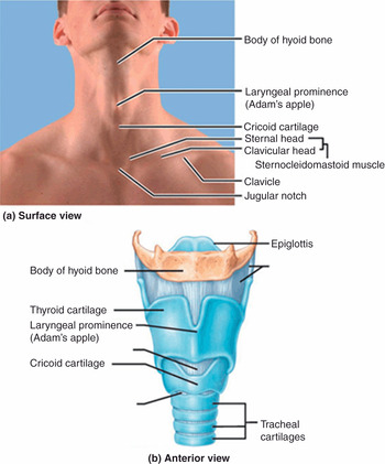
Figure 7.7* Anatomy of the larynx. (a) A view of the anterior extended neck wich shows landmarks relevant for tracheostomies and cricothyroidotomies on the skin surface, as they should be detected in patients. (b) A model of the larynx and part of the trachea, seen in an anterior view. Note the correspondence between surface landmarks and structures in the model.
Choosing the right-sized ETT is even more important in the pediatric population, where the cartilage tissue of airways is fragile and more vulnerable. Formulas based on age, height, and weight have been used for a long time but they are not effective, leading in many cases to multiple attempts at laryngoscopy or the replacement of the ETT [Reference Shibasaki, Nakajima, Ishii, Shimizu, Shime and Sessler21]. In a sample of 192 children, the percentage agreements between US-estimated ETT size and the size estimated as clinically optimal were 98% for cuffed ETTs and 96% for uncuffed ETTs [Reference Shibasaki, Nakajima, Ishii, Shimizu, Shime and Sessler21]. The size of the ETT was chosen by varying the external diameter, according to the US-estimated transverse cricoid diameter (or subglottic diameter) [Reference Shibasaki, Nakajima, Ishii, Shimizu, Shime and Sessler21], similar to adults. The superiority of US-based measurements in comparison to traditional formulas in determining the correct ETT size was confirmed by two studies [Reference Bae, Byon, Han, Kim and Kim22,Reference Schramm, Knop, Jensen and Plaschke23]. In one of them [Reference Bae, Byon, Han, Kim and Kim22], a formula to calculate the internal diameter of an uncuffed ETT, based on the US-determined subglottic diameter, was proposed: 0.705 × subglottic diameter – 0.091. The size of the transverse sugblottic diameter ranged from 4 to 10 mm in that study [Reference Bae, Byon, Han, Kim and Kim22]. Ultrasonography was judged as reliable in the prediction of the ETT size in adolescents [Reference Gupta, Gupta and Rastogi24].
Ultrasonography was also applied to predict the size of double-lumen endobronchial tubes, used to selectively ventilate one lung. This information was based on the outer tracheal width, determined by using both US and CT scans, in transverse sections. A strong correlation of the values of tracheal width between the two techniques confirms the reliability of ultrasonography in determining the diameter of an endobronchial tube (75% of correct determinations) [Reference Sustic, Miletic, Protic, Ivancic and Cicvaric25].
Confirmation of endotracheal tube placement and detection of misplacement
Capnometry, which is the measurement of end-tidal CO2, is used to confirm ETT placement, in elective and emergency situations. Several factors may influence the detection and determination of CO2 by capnometry devices (e.g., cardiac arrest, previous respiratory diseases, consumption of anti-acidic medications), leading to an incorrect assessment of ETT placement, in both situations. In an emergency situation, capnometry is shown to give 7% false-negative (tube in trachea recorded as in the esophagus) and 3% false-positive (tube in esophagus recorded as in the trachea) results [Reference Li26]. Moreover, capnometry is not a real-time examination and needs a ventilation attempt to function [Reference Li26]. Capnometry alone can be unreliable as a means of confirming ETT placement [Reference Li26].
There are at least four US-based modalities to confirm ETT placement: detection of the ETT while it passes through the trachea, detection of the ETT in the trachea, movements of pleural sheets, and movements of the diaphragm. The first two modalities are based on the direct visualization of the ETT and do not require a trial of ventilation. The second two are indirect and based on the movements associated with the combination of lung and pleura; they require a trial of ventilation. These approaches can be used either in elective or in emergency intubations, alone or combined with each other, or can be performed alongside capnometry.
Initial studies on the confirmation of ETT placement by US were carried out on cadavers [Reference Ma, Davis, Schmitt, Vilke, Chan and Hayden27,Reference Weaver, Lyon and Blaivas28] and gave variable results in terms of sensitivity and specificity, probably due to different US approaches and the anatomic conditions related to cadavers. During elective intubation in humans, using a transverse scan at the suprasternal notch level, the sensitivity and specificity of the identification of the intubation as tracheal were 100% for both, and inadvertent esophageal intubations were accurately detected as well [Reference Werner, Smith, Goldstein, Jones and Cydulka29]. Endotracheal tubes may be detected indirectly, through the identification of lung–pleura motion. Lung sliding is the sonographic sign of the moving interface of mutual gliding of visceral and parietal pleura as the lungs expand; it shows bilateral ventilation of the lungs, providing evidence of correct intubation [Reference Chun, Kirkpatrick and Sirois30]. In comparison with auscultation alone, this method of verification of ETT placement can be applied with the same rapidity; it is quicker than the traditional approach based on auscultation and capnography (the graphical visualization of end-tidal CO2 in the form of waves), in non-obese [Reference Pfeiffer, Rudolph, Borglum and Isbye31] and obese patients [Reference Pfeiffer, Bache and Isbye32], for elective cases. The mean time to perform the US examination and to check ventilation was 40 seconds, and the landmark used to place the probe was the second to third intercostal space in the mid-clavicular line [Reference Pfeiffer, Rudolph, Borglum and Isbye31].
Ultrasound-based methods are also useful for the verification of ETT placement in emergency intubations. An approach called tracheal rapid ultrasound examination (TRUE) has been proposed [Reference Chou, Tseng and Wang33]. It consists of a rapid transverse US scan of the neck superior to the suprasternal notch, aimed to detect the presence of the ETT in the trachea. The trachea is identified by the visualization of a hyperechoic A–M interface with reverberation artifacts in the posterior position, so-called “comet-tail” artifacts. The intubation is deemed to be endotracheal if there is one A–M interface with a posterior comet tail and shadowing, and esophageal if there are two A–M interfaces and more than one comet tail with posterior shadowing. The US sign of esophageal intubation is the “double-tract” sign (Figure 7.8). In comparison to capnography, the TRUE exam is faster and more reliable in emergency intubations [Reference Chou, Tseng and Wang33]. It can be applied in noisy environments or where capnography is neither available nor reliable (e.g., cardiac arrest). This method has, in fact, been seen to deliver up to 100% of sensitivity and specificity [Reference Noh and Cho34]. The TRUE approach is accurate also in the detection of ETT during cardiopulmonary resuscitation (CPR), with no discontinuation of external cardiac massage [Reference Chou, Chong and Sim35].
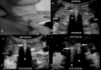
Figure 7.8 The TRUE method for the rapid confirmation of ETT placement. (A) Position of the US probe above the suprasternal notch. (B) A normal trachea. From anterior to posterior there are tracheal wall, A–M interface (arrow), comet-tail artifact (arrowhead), air (black). On the two sides, right and left, there are the lobes of the thyroid gland (ThG). (C) An endotracheal intubation, characterized by one A–M interface (arrow), a comet-tail artifact (arrowhead), and posterior shadowing. (D) An esophageal intubation, characterized by the double-tract sign: presence of two A–M interfaces (arrows), comet-tail artifacts (arrowheads), and posterior shadowing.
Another approach proposed for bedside confirmation of ETT placement in the emergency department is US examination of the anterior neck from the cricothyroid membrane to the suprasternal notch; it is performed until the detection of the ETT and the exclusion of an esophageal intubation [Reference Osman, Chuan and Manikam36]. Bedside identification of the lung sliding sign is also used as a method to confirm ETT placement in emergency departments, with a high positive predictive value (up to 100% in patients with cardiac arrest), similar to chest radiography [Reference Sim, Lien and Chou37]. Recently, diaphragm motion has been studied in the emergency department for ETT confirmation in adults [Reference Hosseini, Talebian, Ghafari and Eslami38]. In this study, the ETT was placed through a rapid sequence intubation and its verification was performed during bag ventilation, applying an US scan in the right subcostal area in proximity to the mid-clavicular line [Reference Hosseini, Talebian, Ghafari and Eslami38] (Figure 7.9). Sensitivity and specificity were 92% and 96%, respectively [Reference Hosseini, Talebian, Ghafari and Eslami38]. In cases in which the accuracy of one US-based approach in the verification of ETT placement is not 100%, it can be maximized by the combination of two approaches; for example, a transcricothyroid scan during intubation plus the detection of lung sliding [Reference Park, Ryu, Yeom, Jeong and Cho39], or a combination of transtracheal US and lung sliding [Reference Saglam, Unluer and Karagoz40]. Using the transcricothyroid scan, as soon as the ETT passes through the larynx it will be possible to see the “snow-storm sign” in longitudinal view [Reference Ma, Davis, Schmitt, Vilke, Chan and Hayden27,Reference Park, Ryu, Yeom, Jeong and Cho39], and the “bullet sign” in transverse view of the larynx. The bullet sign indicates the change of the profile of the cricothyroid membrane from triangular to round [Reference Park, Ryu, Yeom, Jeong and Cho39]. The shadow of the ETT is seen as a round hyperechoic line [Reference Park, Ryu, Yeom, Jeong and Cho39].
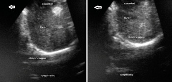
Figure 7.9 Ultrasound image of the diaphragm in the subcostal view (right hemidiaphragm): (left) before ventilation; (right) during positive-pressure ventilation.
Table 7.3 provides an overview of the US-based modalities used to confirm the ETT placement in adults.
| Method | Landmarks | Description | US findings | Remarks | |
|---|---|---|---|---|---|
| Direct confirmation of intubation | Transtracheal ultrasonography [Reference Werner, Smith, Goldstein, Jones and Cydulka29] |
| Detection of the tube inside the trachea or the esophagus [Reference Werner, Smith, Goldstein, Jones and Cydulka29] |
|
|
| TRUE [Reference Chou, Tseng and Wang33] |
| Rapid detection of the ETT inside the tracheal lumen after the completion of the intubation [Reference Chou, Tseng and Wang33] |
|
| |
| Upper airway sonography [Reference Osman, Chuan and Manikam36] |
| Dynamic US transverse (from cricothyroid membrane to suprasternal notch) and sagittal scans of the neck performed until the detection of ETT or esophageal intubation [Reference Osman, Chuan and Manikam36] |
|
| |
| Passage of the ETT [Reference Gupta, Gupta and Rastogi24,Reference Osman, Chuan and Manikam36] |
| Detection of the ETT while it passes through the larynx [Reference Gupta, Gupta and Rastogi24,Reference Osman, Chuan and Manikam36] |
|
| |
| Indirect confirmation of intubation | Lung sliding [Reference Pfeiffer, Rudolph, Borglum and Isbye31,Reference Sim, Lien and Chou37] |
| Bilateral lung sliding shows bilateral expansion of lungs, giving proof of the correct position of the ETT (visually equivalent to auscultation) [Reference Chun, Kirkpatrick and Sirois30] |
|
|
| Diaphragm motion [Reference Hosseini, Talebian, Ghafari and Eslami38] |
| Bilateral motion of the diaphragm is equivalent to bilateral expansion of lungs [Reference Hosseini, Talebian, Ghafari and Eslami38] |
|
|
Direct methods are based on the visualization of the ETT inside the trachea (or the esophagus) or signs related to its passage through the larynx. They do not require a trial of ventilation and are usually performed in B-mode. The ETT is made of plastic material and appears hyperechoic with posterior shadowing. The cuff of the ETT is not visualized, unless it is filled with fluid or air bubbles. Indirect methods show signs of lung expansion, regardless of the position of the ETT. The presence/absence of these signs in one/both lungs provides information about ETT placement. They require a trial of ventilation and are performed in M-mode. Most of these methods are applied in emergency departments, where capnography is unavailable or unreliable. All of them are implemented in real time and at the bedside.
A–M, air–mucosa; CPR, cardiopulmonary resuscitation; ETT, endotracheal tube; TRUE, tracheal rapid ultrasound examination.
In the pediatric population, US-based methods to verify the placement of an ETT rely either on the direct visualization of the tube or on indirect signs of the proper placement of it (i.e., lung sliding or diaphragm motion). To date, verification of intubation has been studied mainly for emergency intubations. The most suitable position for the US scan of the neck is the sniffing position, and probes with low and high frequency are used, both linear and curved [Reference Galicinao, Bush and Godambe42]. Bedside US is fast and feasible in the confirmation of ETT placement in pediatric ICUs [Reference Galicinao, Bush and Godambe42]. The US examination is performed via the cricothyroid membrane; the ETT is identified by the comet-tail sign in transverse view, and by two parallel hyperechoic lines, representing the profile of the ETT, in longitudinal view [Reference Galicinao, Bush and Godambe42]. In newborns, US is reliable in the verification of ETT positioning, with a good agreement between US-determined distance from the ETT tip to the carina and that determined by thoracic radiography [Reference Dennington, Vali, Finer and Kim43]. US can therefore be time-saving and radiation-sparing. An entirely real-time approach is possible as well, as shown by the direct visualization of the vocal cords opening during the passage of the ETT, and the enhancement of the posterior shadowing of the trachea, even if this sign is not always detectable [Reference Marciniak, Fayoux, Hebrard, Krivosic-Horber, Engelhardt and Bissonnette44]. These findings are shown through a transverse scan starting from the suprasternal notch and proceeding to the level of the glottis [Reference Marciniak, Fayoux, Hebrard, Krivosic-Horber, Engelhardt and Bissonnette44].
Diaphragm motion is an indirect method to assess ETT placement. Two US windows are described in children: one is the subxiphoid window, at the mid-upper abdomen, which is the most used, and the other is the lower chest, at the mid-axillary line, right and left [Reference Hsieh, Lee and Lin45]. M-mode and B-mode US are needed [Reference Hsieh, Lee and Lin45]. The bilateral motion of the diaphragm is equivalent to the bilateral expansion of the lungs and provides evidence of the placement of the ETT above the carina [Reference Hsieh, Lee and Lin45]. In one study, even though the agreement between US diaphragm scan and chest radiography in the confirmation of ETT placement was suboptimal, US results were faster, highly reproducible amongst sonographers, and detected more misplacements than standard confirmation alone [Reference Kerrey, Geis, Quinn, Hornung and Ruddy46]. Currently, diaphragmatic US can be used together with other techniques to confirm ETT placement in children. Further studies are required to better clarify the role of such an approach. Recently, a combined US-based approach was applied in newborns, using a transverse transtracheal scan and the detection of lung sliding [Reference Mora-Matilla, Alonso-Quintela and Oulego-Erroz47]. The lung sliding was detected in all patients, and the ETT directly identified in 7 out of 10 intubations. The limited sample size (7 newborns) limits the conclusions, and additional research is needed.
Ultrasonography has also been implemented to evaluate the placement of double-lumen ETTs [Reference Sustic, Protic, Cicvaric and Zupan48]. A rapid US examination based on the visualization of lung sliding and diaphragm motion, along with a clinical assessment after intubation, increases specificity, accuracy, and positive predictive value, in comparison to those obtained through clinical evaluation alone [Reference Sustic, Protic, Cicvaric and Zupan48].
The main sites of tube misplacement are the esophagus and the right main bronchus; the accidental intubation of the left main bronchus is also possible, even if less frequent. Esophageal intubation is associated with emesis and aspiration, especially if a trial of ventilation is performed; bronchial intubation can lead to atelectasis/collapse of the excluded lung and barotrauma of the ventilated lung, leading to pneumothorax. Ultrasonography has sensitivity and specificity of 100% in detecting an intubation as esophageal [Reference Milling, Jones and Khan49,Reference Muslu, Sert and Kaya50]. Using a transverse scan of the neck through the cricothyroid membrane, the esophageal intubation is described as a hyperechoic curve line that represents the superficial part of the ETT, accompanied by a distal dark area (shadowing), located deeply and laterally to the trachea [Reference Milling, Jones and Khan49]. Other authors use a transverse scan above the suprasternal notch and describe the “opening” of the esophageal lumen in the paratracheal space when the ETT is inside the esophagus [Reference Muslu, Sert and Kaya50] (Figure 7.10). This detection takes 3 seconds [Reference Muslu, Sert and Kaya50]. At the level of the thyroid lobes, the “intubated esophagus” appears as an oval structure to the left of the trachea and posterior to the left thyroid lobe [Reference Hoffmann and Gullett51]. If a bronchial intubation occurs, the absence of lung sliding in the excluded lung and its concomitant presence in the other lung may be sufficient, in many cases, to consider pulling the ETT back [Reference Blaivas and Tsung52]. In children, the absence of lung sliding in the excluded lung may be accompanied by the detection of absence of diaphragm motion on the same side [Reference Blaivas and Tsung52]. All these evaluations are done in real time and do not require the assistance of imaging specialists.
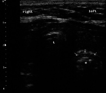
Figure 7.10 Ultrasound view of an esophageal intubation (transverse scan). It is possible to see the lumen of the esophagus (e) opened by the tube (arrows) in the paratracheal space (left); t indicates the trachea.
Tracheostomy
Tracheostomy is another way to ensure airway patency; it makes the ventilation of lungs possible by bypassing the larynx. Many, but not all, indications for tracheostomy belong to the intensive care setting: prolonged need for intubation and mechanical ventilation, failed trials of extubation, and need for better bronchial toilet [Reference Mallick and Bodenham53]. Advantages associated with tracheostomy in comparison to endotracheal intubation include the lack of sedation to tolerate the inner cannula, the allowance of spontaneous breathing, more efficient cough and phonation, and the promotion of earlier mobilization [Reference Mallick and Bodenham53]. Other indications include trauma or surgery of the face or neck, bypass of upper airway obstructions (e.g., malignancies, laryngeal stenosis, bilateral recurrent laryngeal nerve palsy), and prevention of aspiration (e.g., pharyngolaryngeal incompetence for brain or spinal cord injury) [Reference Mallick and Bodenham53].
Two approaches are described, one percutaneous, the other open or surgical. Percutaneous dilatational tracheostomy (PDT) can be performed at the bedside and has a shorter learning curve. It is the procedure most commonly performed. Surgical tracheostomy has to be performed in the operating room, has a longer learning curve, and presents a greater risk of infection. Another way to provide airway access bypassing the larynx is cricothyrodotomy, and this has to be implemented in some cases of cannot intubate–cannot ventilate scenarios. For all these procedures, it is possible to apply ultrasonography as a means for pre-procedural evaluation and/or guidance during the implementation of the maneuver (e.g., in real time). Complications are divided into immediate, early, and late; see reference [Reference Mallick and Bodenham53] for details.
Pre-procedural assessment
The aim is to identify the anatomy and the relevant landmarks for every single patient in order to minimize complications, which mostly derive from the injury to the structures close to the site of the tracheostomy, from an unfavorable anatomy, or from congenital or acquired anomalies. In a series of 50 patients, ultrasonography was seen to be feasible and rapid in the visualization of structures of the infrahyoid region involved in tracheostomies, and the distances between landmarks and sites of possible damage were calculated for every patient [Reference Bertram, Emshoff and Norer54]. Once the site of the puncture is identified prior to performing a PDT, the information further obtained by ultrasonography identifies, in vivo, the vessels deemed as “vulnerable” (jugular veins, carotid arteries) and leads to appropriate decision making: for example, implementation of the maneuver by a more experienced professional, elective ligature of the vessels, referral of the patient to a surgical tracheostomy [Reference Hatfield and Bodenham55], or a change of technique or size of tube [Reference Muhammad, Major and Patton56,Reference Muhammad, Patton, Evans and Major57].
Ultrasonography also serves as a means to confirm the site of the puncture. After a conventional evaluation it can be changed and replaced by one more suitable (24% of cases) [Reference Kollig, Heydenreich, Roetman, Hopf and Muhr58], to avoid vessel puncture, tracheal ring fractures, or tracheal wall lesions, or the formation of a paramedian stoma [Reference Sustic and Zupan59]. This increases safety and significantly affects neither procedural time [Reference King60] nor costs [Reference Kollig, Heydenreich, Roetman, Hopf and Muhr58]. Cases of aberrant anatomic course of neck structures have been described (e.g., right common carotid artery [Reference Khan and Alzahrani61], arterial brachiocephalic trunk [Reference Otchwemah, Defosse, Wappler and Sakka62], pretracheal veins [Reference Flint, Midde, Rao, Lasman and Ho63], and trachea [Reference Orr, Stephens and Mitchell64]) which were detected by pre-procedural ultrasonography. Appropriate strategies may be implemented in a timely fashion and disastrous consequences avoided [Reference Flint, Midde, Rao, Lasman and Ho63]. The relevant landmarks include the thyroid and cricoid cartilages, tracheal rings, thyroid gland, and the carotid and jugular vessels [Reference Rudas65] (Figure 7.7*). Ultrasonography helps in the detection of landmarks even when they are not clinically demonstrable (e.g., in the case of obesity and/or a short neck), improving the quality of the performance and decreasing the number of attempts [Reference Dinsmore, Heard and Green66].
Ultrasonography can also be used for surgical tracheotomies, in the preoperative detection of the trachea [Reference Munir, Hughes, Sadera and Sherman67]. In regard to cricothyroidotomy, ultrasonography gives the possibility to rapidly identify the relevant landmarks [Reference Nicholls, Sweeney, Ferre and Strout68] (Figure 7.7*). Sagittal, parasagittal, and transverse scans are used, and the landmarks can be rapidly identified and the cricothyroid membrane marked [Reference Nicholls, Sweeney, Ferre and Strout68]. To date, this preventive US-based approach to cricothyroidotomies has been the most studied.
It should be noted that the availability of US and the possibility to perform a pre-procedural evaluation does not influence the decision as to whether to perform a tracheostomy or not; but after this decision has been taken, US information helps on how to do it [Reference Muhammad, Patton, Evans and Major57].
Performance of tracheostomies
The most used approach for PDT is that of Ciaglia, performed applying the Seldinger technique in a sterile field, under both general and local anesthesia. The neck can be extended or in a neutral position. Optimal sites of tracheal puncture are between the first and the second tracheal ring or the second and the third tracheal ring; such locations, in most cases, avoid subglottic stenosis and thyroid damage. The use of either an in-plane or an out-of-plane US approach has been described [Reference Rudas65].
Tracheostomy under US guidance is performed as follows. A clear visualization of the tracheal rings, cricoid, and thyroid cartilages should be obtained through a longitudinal scan of the anterior neck to identify or confirm the site of the puncture; this corresponds to a point in the midline below the chosen tracheal ring. The probe is then moved proximally and placed above this tracheal ring [Reference Sustic, Kovac, Zgaljardic, Zupan and Krstulovic69]. A transverse incision, of about 1–2 cm, of cutaneous and subcutaneous tissues is performed under local anesthesia, parallel and next to the probe. The trachea is then punched in the midline and a guidewire inserted through it [Reference Sustic, Kovac, Zgaljardic, Zupan and Krstulovic69] (Figures 7.11* and 7.12*). By applying this method properly, cranial misplacement of the cannula (above the first tracheal ring) and fractures of tracheal rings can be avoided [Reference Sustic, Kovac, Zgaljardic, Zupan and Krstulovic69]. US guidance facilitates successful tracheal puncture and insertion of a guidewire, as confirmed by CT scan in cadavers [Reference Kleine-Brueggeney, Greif and Ross70]. An advantage of US-guided tracheostomy is the lower incidence of hypercarbia and respiratory acidosis in comparison to guidance by bronchoscopy; this is an element to be considered according to the clinical setting [Reference Reilly, Sing and Giberson71]. During bronchoscopy, the transillumination of the neck at the site of the puncture is not always optimal [Reference Reilly, Sing and Giberson71]. On the other hand, since the presence of air inside the trachea prevents its posterior wall from being correctly visualized by US, accidental damage could be possible. For this reason, a specific device, called a stopper, was introduced to enhance the safety of the procedure [Reference Sustic, Kovac and Krstulovic72]. Percutaneous tracheostomies were seen for a long time as poorly suitable for obese patients, due to the lack of identification of landmarks, the short neck, and the increased incidence of complications. It has been shown that PDT is feasible under US guidance in obese patients, in a short time, with a similar complication rate in obese and non-obese patients [Reference Guinot, Zogheib and Petiot73]. The guidance of the needle was performed through an out-of-plane approach in a transverse view. Obesity is thus no longer a contraindication for PDT if performed under US guidance [Reference Guinot, Zogheib and Petiot73]. The control of airways during the performance of the procedure can be assured by the application of a laryngeal mask airway (LMA) in obese patients [Reference Sustic, Zupan and Antoncic74].
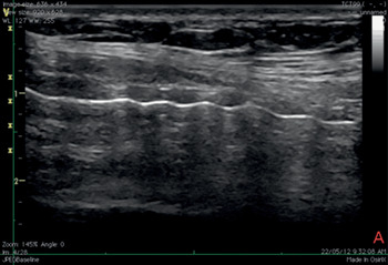
Figure 7.11* Sagittal ultrasound view of the neck during tracheostomy. It is recommended to begin the procedure with a longitudinal scan to accurately determine the site of the puncture.
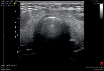
Figure 7.12* Transverse ultrasound view of the neck during tracheostomy. It is possible to see the tracheal wall with the A–M interface and the image of the needle tip inside the lumen of the trachea with anterior acoustic shadowing.
Tracheostomy using US guidance has been shown to be feasible as well as accurate and safe in various categories of patients [Reference Rajajee, Fletcher, Rochlen and Jacobs41]. Tracheal puncture is significantly more accurate with real-time US than with a landmark-based technique; puncture attempts and procedural complications are significantly reduced using a US-based technique [Reference Rudas75]. The US technique comprises a pre-procedural evaluation to identify landmarks, and to estimate the thickness of soft tissues in the anterior neck and the internal diameter of the trachea, in order to decide on an appropriate size of tracheostomy tube [Reference Rajajee, Fletcher, Rochlen and Jacobs41]. Using this approach, the procedure can be entirely guided by transverse US images, at the level of the sternal notch: a needle is perpendicularly inserted through the neck in the midline and advanced until a sensation of loss of resistance is felt; this is the sign of the advancement of the needle into the tracheal lumen, which is confirmed by the aspiration of air into a syringe filled with saline and attached to the needle. In this phase, the acoustic shadow of the needle, followed by the displacement of tissues, is visible (Figure 7.13). After the passage of a guidewire and the removal of the needle, a cannula is inserted through the stoma (created by an incision at the point of guidewire entry) and secured. The insertion of the cannula is facilitated by the use of a dilator. The detection of bilateral lung sliding will confirm the correct placement of the cannula [Reference Rajajee, Fletcher, Rochlen and Jacobs41]. The longitudinal real-time approach has been described and deemed valid as well [Reference Rodriguez and Esteves76] (Figure 7.14*). Recent studies confirm the feasibility of real-time, US-guided PDT [Reference Rudas75,Reference Chacko, Nikahat, Gagan, Umesh and Ramanathan77,Reference Taha, Shafie and Mostafa78] (Figure 7.15*). In one of them a new dilator in the form of a balloon has been used [Reference Taha, Shafie and Mostafa78]. Bronchoscopy can be used to confirm US findings at the beginning of the procedure [Reference Rajajee, Fletcher, Rochlen and Jacobs41] or after, to confirm the position of the cannula [Reference Chacko, Nikahat, Gagan, Umesh and Ramanathan77] or to exclude tracheal injuries [Reference Taha, Shafie and Mostafa78].
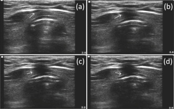
Figure 7.13 Transverse ultrasound scan of the neck during tracheostomy. The tip of the needle is visualized as the white point inside the tracheal lumen with anterior acoustic shadowing. The four images in sequence (a–d) show the displacement of tissues during the passage of the needle.
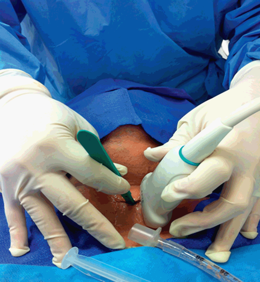
Figure 7.14* Performance of tracheostomy using a longitudinal real-time US-based approach. Some authors have suggested that this approach allows for a better visualization of the tracheal tube, both when it is in the trachea and during its removal, and the guidewire passing through the tracheal wall and tissues, following its course until it is inside the trachea [Reference Rodriguez and Esteves76].
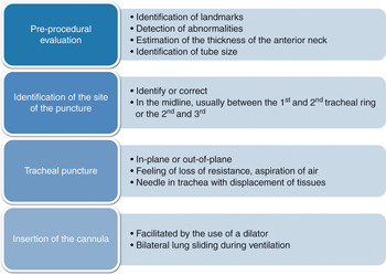
Figure 7.15* The performance of real-time US-guided percutaneous dilatational tracheostomy (PDT). The procedure is performed entirely under the guidance of transverse or longitudinal (or both) US imaging. The correct application of ultrasonography improves the performance, with reduced number of attempts, increased number of midline punctures, and reduced complication rate. Note that the skin incision is performed after the tracheal puncture and the passage of the guidewire (see text), with the aim of dilating the opening, along with the dilator, and facilitating the passage of the cannula.
Patients who have suffered a trauma or a spinal cord injury need an anterior cervical spine fixation (ACSF) to prevent damage to respiratory nuclei following spine movements. These patients often need a tracheostomy to aid weaning from mechanical ventilation and in order to maintain a clear airway [Reference Sustić, Krstulović and Eskinja79]. In such patients, US-guided percutaneous tracheostomy has been shown to be as safe as open tracheostomy, faster, less expensive, performed at the bedside, and presenting less risk of stoma infection [Reference Sustić, Krstulović and Eskinja79]. It is important to note that the procedure performed under US guidance does not require extension of the neck [Reference Sustić, Krstulović and Eskinja79,Reference Sustic, Zupan, Eskinja, Dirlic and Bajek80].
Ultrasound guidance has been successfully used for the localization of the cricothyroid membrane and the placement of a cannula for tracheal anesthesia and fiberoptic intubation, as well as when performing a guided cannula cricothyroidotomy [Reference Suzuki, Iida and Kunisawa81]. A previous study showed the potential utility of having landmarks relevant for an urgent cricothyrodotomy ready in patients [Reference Nicholls, Sweeney, Ferre and Strout68] (Figures 7.7* and 7.16*). However, evidence in this field is currently limited, owing to the rarity of the situations in which it is required; additional studies will clarify the role of ultrasound in such cases.
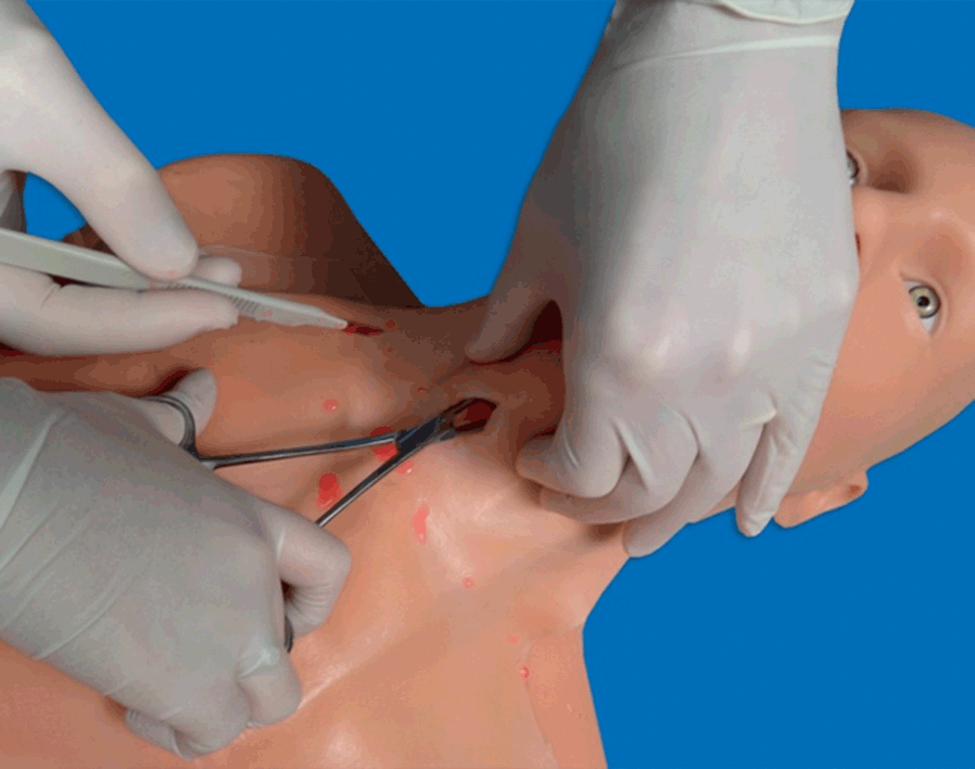
Figure 7.16* Performance of cricothyroidotomy (simulation on a manikin). It is an urgent and life-saving procedure to be performed in the cannot intubate–cannot ventilate scenario. It can also be performed for translaryngeal anesthesia. Ultrasonography helps to detect the relevant landmarks, mainly the cricothyroid membrane, facilitating the maneuver.
Other applications
Upper airway anesthesia
This aims to suppress or attenuate protective airway reflexes and create conditions suitable for awake fiberoptic intubation. Two methods have been described: translaryngeal anesthesia, via cricothyroid injection, serves to apply local anesthetics to the respiratory mucosa of subglottic regions; superior laryngeal nerve block (SLNB) provides anesthesia to the supraglottic larynx [Reference Green and Tsui82].
The translaryngeal block consists of an injection of local anesthetic into the tracheal lumen [Reference De Oliveira, Fitzgerald and Kendall83]. Its use has been reported in a case of fiberoptic intubation for a morbidly obese patient: a transverse US scan of the neck at the level of the thyroid and cricoid cartilages allowed the authors to perform a puncture in the space below the thyroid cartilage, in the midline of the cricothyroid membrane [Reference De Oliveira, Fitzgerald and Kendall83]. The aspiration of air into the attached syringe confirmed the entrance into the larynx, after which the local anesthetic was injected [Reference De Oliveira, Fitzgerald and Kendall83].
Sometimes translaryngeal anesthesia cannot suppress the cough reflex and can cause a certain degree of airway compromise; the conditions for fiberoptic intubation may be suboptimal, due to the subglottic anesthesia only. Ultrasound-guided SLNB provides anesthesia for lingual radix, epiglottis, and the cricothyroid muscle, which should be more complete for the performance of awake fiberoptic intubation [Reference Iida, Suzuki, Kunisawa and Iwasaki84]. The main landmarks for an SLNB are the greater horn of the hyoid bone and the superior laryngeal artery. In a case of laryngeal abscess drainage under general anesthesia, awake fiberoptic intubation was successfully performed under both US-guided bilateral SLNB and translaryngeal block [Reference Iida, Suzuki, Kunisawa and Iwasaki84]. The hyoid bone was detected in a transverse view and the block performed in an in-plane configuration [Reference Iida, Suzuki, Kunisawa and Iwasaki84]. Bilateral US-guided SLNB was successfully applied also in a case of difficult intubation for spine surgery [Reference Manikandan, Neema and Rathod85]. However, even if in such cases landmarks were properly visualized and the block accomplished, in none of them was direct visualization of the nerve described. A recent study showed the US visualization of the nerve by using a linear, hockey-stick-shaped probe, in volunteers: first, a longitudinal scan of the submandibular region identified the greater horn of the hyoid bone, and a transverse scan identified the thyrohyoid membrane [Reference Kaur, Tang, Sawka, Krebs and Vaghadia86]. The probe was then turned cranially and the nerve visualized. The accuracy of this approach was confirmed in cadavers through a dye test [Reference Kaur, Tang, Sawka, Krebs and Vaghadia86].
Laryngeal mask airway confirmation and risk of aspiration
The use of an LMA may be associated with a risk of aspiration, in the presence of predisposing conditions (obesity, not empty stomach due to inadequate fasting or gastroparesis, LMA misplacement, or lack of tight adherence to the pharynx). Ultrasonography is a reliable tool to confirm the correct placement of an LMA, as shown by the agreement between the US grade and the fiberoptic grade of LMA position, after LMA placement and before removal [Reference Gupta, Srirajakalidindi, Habli and Haber87]. The visualization of the cuff of an LMA is obtained through transverse scans of the neck [Reference Gupta, Srirajakalidindi, Habli and Haber87]. Ultrasonography provides the possibility of making a detailed assessment of gastric content and volume [Reference Perlas, Chan, Lupu, Mitsakakis and Hanbidge88]. It is possible to explore the body, the fundus, and the antrum, each of them by specific plane scans and acoustic windows. A linear correlation between antral cross-sectional area (CSA) and gastric volume was found up to 300 mL of fluid, with the subject placed in the right lateral position [Reference Perlas, Chan, Lupu, Mitsakakis and Hanbidge88]. The antrum is the most reliable amongst gastric regions to give information about gastric content and its nature (e.g., full, empty, solid, liquid, gas). Using a number of demographic variables (age, height, and weight) two formulas have been constructed to predict gastric volume, based on a measurement of the CSA [Reference Perlas, Chan, Lupu, Mitsakakis and Hanbidge88]:
In the context of urgent surgery, a quicker method which allows for a rapid evaluation of gastric content before endotracheal intubation has been demonstrated [Reference Koenig, Lakticova and Mayo89]. Using a low-frequency probe, the stomach is detected in the upper left quadrant of the abdomen through longitudinal (in the mid-axillary line, using the spleen and left hemidiaphragm as landmarks) and transverse views [Reference Koenig, Lakticova and Mayo89]. Gastric fluid appears as a hypoechoic material surrounded by the gastric walls, and solid materials are seen as hyperechoic particles floating in the gastric fluid. This information is helpful for anesthesiologists to evaluate the risk of aspiration and in the decision to place a nasogastric tube before the induction [Reference Koenig, Lakticova and Mayo89], or even on the possibility to use a supraglottic device for airways.
Extubation
The use of cuffed ETTs may be accompanied by the development of complications such as laryngeal edema, which displays as a form of severe respiratory distress after extubation, called stridor. The detection of a narrowed width of the subglottic area, due to a vocal cord swelling, identifies patients at risk to develop stridor, before the extubation. The accuracy of the cuff leak test is variable, and direct laryngoscopy cannot provide this information in intubated patients [Reference Ding, Wang, Wu, Chang and Yang90]. A study has shown that US easily visualizes the laryngeal air-column width and is reliable in its measurement [Reference Ding, Wang, Wu, Chang and Yang90]. The US-based measurement of laryngeal air-column width identifies an increased risk for stridor and can predict its occurrence. This enables anesthesiologists to apply additional measures during and after extubation to enhance patient safety.
Two additional applications
As previously reported, patients with trauma require a fixation of the cervical spine to avoid, or prevent deterioration of, spinal cord damage. These patients are usually intubated in the presence of devices, applied to them, which ensure a stabilization of the spinal cord. Ultrasonography has been shown to be a reliable tool to evaluate the range of movements of the cervical spine during manual stabilization, in real time and three dimensions, while endotracheal intubation is being performed [Reference Gercek, Wahlen and Rommens91]. The anesthesiologist will select the airway device which creates the minimum dislocation of the neck.
One study has described an experience of ultrasonography applied to airway management as a part of a mobile telemedicine program [Reference Sibert, Ricci and Caputo92]. Healthcare providers acting during patient transport were linked to a central remote workstation with physicians and other operators who provided real-time audio and video information about the images useful to manage the patient. This may be a reality using high-technology portable equipment with an adequately trained team.
Airway ultrasonography has proven utility and safety, as long as it is correctly implemented. The wider application of US to airways will depend on adequate training of healthcare providers, which can be performed on patients and enhanced by suitable tools, as shown for simulation in a recent article [Reference Schroeder, Ramamoorthy and Galgon93].
Conclusions
Ultrasonography may improve the management of airways. Several applications for this technology are available in both adult and pediatric patients (Table 7.4). Information obtained through US is reliable, reproducible, and quick, saving time and money, and promoting collaboration among professionals. This is true in elective conditions and is most important during emergencies, where rapid decision making and interaction skills are essential, both in diagnostics and in follow-up after treatment. To date, even though some areas of US application to airways require additional research, it is possible to state that it has become a real “virtual stethoscope” in the hands of skilled professionals, enlarging their perspectives on diagnosis and therapy.
| Applications | Results | Advantages | Disadvantages | |
|---|---|---|---|---|
| Intubation | Pre-intubation assessment |
|
| Common to all US-based techniques: inter-individual variability, influence of bone and air, technical issues related to patients (e.g., suboptimal acoustic window, obesity, lack of compliance) |
|
| |||
| Confirmation of ETT placement |
|
| ||
| Tracheostomy | Pre-procedural assessment |
|
| |
|
| |||
|
| |||
|
| |||
| Performance of tracheostomy |
|
| ||
| Performance of cricothyroidotomy |
|
| ||
| Other applications | Upper airway anesthesia |
|
| |
|
| |||
| Confirmation of LMA placement |
|
| ||
| Assessment of gastric content |
|
| ||
| Extubation |
|
| ||
| Trauma |
|
| ||
|
| |||
| Telemedicine |
|
|
Each field of application has several results and advantages. The possibility to objectively provide information about airways makes communication among professionals faster and more efficient, allowing the exchange of experiences even in different hospitals or settings. The disadvantages related to the use of sonography are virtually nonexistent: they are common to all US-based techniques, and can also be optimized with adequate training.
ETT, endotracheal tube; LMA, laryngeal mask airway; RSI, rapid sequence induction; SGD, supraglottic device.


