1. INTRODUCTION
With the rapid development and evolution of the BeiDou Global Navigation Satellite System (GNSS), the signal design is facing some new challenges. At the B1 frequency, the early BeiDou regional (Phase II) system is transmitting a Quadrature Phase Shift Keying (2) (QPSK(2)) signal at 1561·098 MHz (Liu et al., Reference Liu, Du, Zhan and Zhai2010). However, the centre frequency for the BeiDou global system (Phase III) is 1575·42 MHz (Zhang et al., Reference Zhang, Zhou and Wang2011). For the B2 signal, two service signals need to be transmitted at the B2a (1176·45 MHz) and B2b (1207·14 MHz) frequencies, respectively (Tang et al., Reference Tang, Zhou, Hu, Ran, Liu and Zhou2010). In order to reduce the signal distortion and propagation time instability (Lestarquit et al., Reference Lestarquit, Artaud and Issler2008), it is necessary to combine these signals located at adjacent frequencies into a constant envelope composite signal. The purpose of a constant envelope is to maximize the efficiency of the High-Power Amplifier (HPA) and reduce nonlinear distortions (Dafesh and Cahn, Reference Dafesh and Cahn2009). On the other hand, for GNSS signal design, how to best allocate power between data component and pilot component is not simple, and the final solution is usually a trade-off between navigation data bit rate and signal power split (Won et al., Reference Won, Eissfeller, Anderas, Floch, Zanier and Colzi2012). Hence, the power allocation scheme may change at any time. In order to simplify the online reconstructing function in the payload transmitter, a demand is that the Power Allocation Ratio (PAR) between signal components can be easily adjusted. Thus the dual-sideband constant envelope modulation technique with adjustable PAR is desired.
Traditional constant envelope modulation techniques, including Interplex (Butman and Timor, Reference Butman and Timor1972), Coherent Adaptive Subcarrier Modulation (CASM) (Dafesh et al., Reference Dafesh, Nguyen and Lazar1999) and Phase-Optimised Constant-Envelope Transmission (POCET) (Dafesh and Cahn, Reference Dafesh and Cahn2009), mainly focus on signals with the same carrier frequency. Alternative Binary Offset Carrier (AltBOC) (Rebeyrol et al., Reference Rebeyrol, Julien, Macabiau, Ries, Delatour and Lestarquit2007; Lestarquit et al., Reference Lestarquit, Artaud and Issler2008) can combine two QPSK signals located at different carrier frequencies into a constant envelope signal, and AltBOC is proposed for the Galileo E5 signal (Galileo OS SIS ICD, 2010). Time Division AltBOC (TD-AltBOC) (Tang et al., Reference Tang, Zhou, Wei, Yan, Liu, Ran and Zhou2011) and Time-Multiplexed Offset Carrier-Quadrature Phase Shift Keying (TMOC-QPSK) (Shivaramaiah and Dempster, Reference Shivaramaiah and Dempster2013) integrate time multiplex technology to AltBOC modulation, which can achieve a similar function to AltBOC. Nevertheless, these signal components in the three techniques have to share the same power level. The POCET method can be used to combine GNSS signals at different carrier frequencies (Dafesh and Cahn, Reference Dafesh and Cahn2011). However, this method is based on numerical optimisation and provides little information on the signal structure. To solve the multiplexing problem of the Beidou B1 signal, non-symmetrical AltBOC multiplexing (Zhu et al., Reference Zhu, Yao, Lu and Feng2012) and unbalanced AltBOC (Zhang et al., Reference Zhang, Zhou and Wang2013) were developed. Obviously, these techniques are only applicable for the specific case. In addition, Zhang (Reference Zhang2013) proposed the generalised AltBOC modulation that multiplexes two QPSK-like signals with unequal power. However, the power between data component and pilot component at the same sideband has to be equal. Yao and Lu (Reference Yao and Lu2012; Reference Yao and Lu2013b) proposed Asymmetric Constant Envelope Double Sideband (ACED) modulation to achieve dual-frequency constant envelope multiplexing, in which the PAR between signal components can be adjusted. However, the required driving clock rate to generate the ACED signal would change for different power allocation schemes. The rate is even up to 24 times subcarrier frequency for some special cases (Yao and Lu, Reference Yao and Lu2013a), which would obviously increase the complexity of signal generation in the payload transmitter. To reduce the driving clock rate, a simplification method for ACED modulation was proposed (Zhang et al., Reference Zhang, Yao and Lu2014), but this results in performance degradation in terms of combination efficiency.
The aim of this paper is to develop a dual-sideband constant envelope modulation technique with adjustable PAR for GNSS application, and the proposed signals can be easily generated in the satellite payload transmitter. Thus, we propose the General AltBOC (GAltBOC) modulation technique in this paper, which can be seen as an extension of AltBOC modulation. This technique has almost all the advantages of AltBOC, meanwhile, the PAR between signal components is adjustable. The proposed GAltBOC modulation signal can be generated by phase Look-up Table (LUT). In contrast to ACED modulation, the driving clock rate does not increase when adjusting the PAR. For a given PAR scheme, in order to further improve the combination efficiency, we introduce the interlacing technique and develop the Interlacing GAltBOC (IGAltBOC) modulation scheme.
The remainder of the paper is organised as follows. Section 2 briefly reviews the AltBOC and ACED modulation, and derives the proposed GAltBOC technique. Section 3 describes three representative cases of GAltBOC modulation as well as the signal properties. Section 4 introduces the IGAltBOC modulation, and provides the structure of IGAltBOC modulation. Section 5 presents the simulation results, and analyses the implementation complexities. Finally, Section 6 concludes the paper.
2. GENERAL ALTBOC MODULATION
Before we begin to introduce the GAltBOC modulation, we first review the AltBOC modulation and ACED modulation.
2.1. AltBOC modulation
AltBOC modulation can provide different services at the lower and upper sideband, and each service signal includes a data and a pilot component. The baseband expression of constant envelope AltBOC modulation is expressed as (Shivaramaiah and Dempster, Reference Shivaramaiah and Dempster2009):
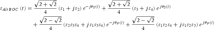
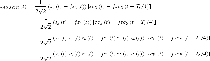 $$\eqalign{{s_{AltBOC}}\left( t \right) & = \displaystyle{1 \over {2\sqrt 2}} \left( {{s_1}\left( t \right) + j{s_2}\left( t \right)} \right)\left[ {s{c_S}\left( t \right) - js{c_S}\left( {t - {{{T_s}} / 4}} \right)} \right] \cr & \quad + \displaystyle{1 \over {2\sqrt 2}} \left( {{s_3}\left( t \right) + j{s_4}\left( t \right)} \right)\left[ {s{c_S}\left( t \right) + js{c_S}\left( {t - {{{T_s}} / 4}} \right)} \right] \cr & \quad + \displaystyle{1 \over {2\sqrt 2}} \left( {{s_2}\left( t \right){s_3}\left( t \right){s_4}\left( t \right) + j{s_1}\left( t \right){s_3}\left( t \right){s_4}\left( t \right)} \right)\left[ {s{c_P}\left( t \right) - js{c_P}\left( {t - {{{T_s}} / 4}} \right)} \right] \cr & \quad + \displaystyle{1 \over {2\sqrt 2}} \left( {{s_1}\left( t \right){s_2}\left( t \right){s_4}\left( t \right) + j{s_1}\left( t \right){s_2}\left( t \right){s_3}\left( t \right)} \right)\left[ {s{c_P}\left( t \right) + js{c_P}\left( {t - {{{T_s}} / 4}} \right)} \right]} $$
where T s is the period of the subcarrier functions.  $j = \sqrt { - 1} $ is the imaginary unit. s 1(t) and s 2(t) denote the data component and pilot component at the lower sideband, respectively. s 3(t) and s 4(t) denote the data component and pilot component at upper sideband, respectively. s 1(t),s 2(t), s 3(t) and s 4(t) are binary Pseudo Random Noise (PRN) code signals. s 2(t)s 3(t)s 4(t), s 1(t)s 3(t)s 4(t), s 1(t)s 2(t)s 4(t) and s 1(t)s 2(t)s 3(t) represent the product signals. For conciseness, at times the time variable t of s 1(t),s 2(t), s 3(t) and s 4(t) is ignored. Then s 1(t),s 2(t), s 3(t) and s 4(t) are expressed as s 1, s 2, s 3 and s 4 respectively. sc S(t) and sc P(t) represent the four-valued subcarrier functions for the single signals and the product signals respectively, whose waveforms in a period are illustrated in Figure 1 (Galileo OS SIS ICD, 2010).

Figure 1. One period of the two subcarrier functions in AltBOC Modulation.
Figure 1 shows that every subcarrier period is sub-divided into eight equal sub-periods. During each sub-period, the subcarrier coefficients remain constant. Equation (1) can be rewritten as (Lestarquit et al., Reference Lestarquit, Artaud and Issler2008):
 $$\eqalign{{s_{AltBOC}}\left( t \right) & = \displaystyle{{\sqrt {2 + \sqrt 2}} \over 4}\left( {{s_1} + j{s_2}} \right){e^{ - j{\theta _S}\left( i \right)}} + \displaystyle{{\sqrt {2 + \sqrt 2}} \over 4}\left( {{s_3} + j{s_4}} \right){e^{\,j{\theta _S}\left( i \right)}} \cr & \quad + \displaystyle{{\sqrt {2 - \sqrt 2}} \over 4}\left( {{s_2}{s_3}{s_4} + j{s_1}{s_3}{s_4}} \right){e^{ - j{\theta _P}\left( i \right)}} + \displaystyle{{\sqrt {2 - \sqrt 2}} \over 4}\left( {{s_1}{s_2}{s_4} + j{s_1}{s_2}{s_3}} \right){e^{\,j{\theta _P}\left( i \right)}}} $$
where 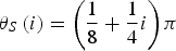 ${\theta _S}\left( i \right) = \left( {\displaystyle{1 \over 8} + \displaystyle{1 \over 4}i} \right)\pi $,
 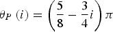 ${\theta _P}\left( i \right) = \left( {\displaystyle{5 \over 8} - \displaystyle{3 \over 4}i} \right)\pi $. i = 0, 1, 2, … , 7 represents the eight sub-periods.
Equation (2) shows that s AltBOC(t) can be seen as a constant envelope composite signal of the four binary signals during each sub-period. In different sub-periods, only the phase angles of the single signals and the product signals change. Figure 2 shows the signal vectors in the first two sub-periods of subcarrier. After one sub-period, the phase angles of s 1 and s 2 would decrease 45° along the clockwise direction, and the angles of s 3 and s 4 would increase 45° along the counter clockwise direction (Zhang et al., Reference Zhang, Li, Zhou and Wang2012).
Figure 2. Signal vectors. (a) The first sub-period. (b) The second sub-period.
2.2. ACED modulation
ACED modulation can also combine two QPSK signals located at two adjacent carrier frequencies into a constant envelope signal. In ACED modulation, these signal components can have an arbitrary power ratio (Yao and Lu, Reference Yao and Lu2013c).
As indicated previously, s 1, s 2, s 3 and s 4 are four binary PRN code signals. Their nominal powers are  ${P_{{s_1}}}, {P_{{s_2}}},{\rm }{P_{{s_3}}}$ and
  ${P_{{s_4}}}$ respectively. Considering the allocated power, the signal components of four channels are expressed as
 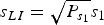 ${s_{LI}} = \sqrt {{P_{{s_1}}}} {s_1}$,
 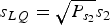 ${s_{LQ}} = \sqrt {{P_{{s_2}}}} {s_2}$,
  ${s_{UI}} = \sqrt {{P_{{s_3}}}} {s_4}$ and
  ${s_{UQ}} = \sqrt {{P_{{s_4}}}} {s_4}$. Then the baseband expression of ACED modulation is as follows:
 $${s_{ACED}}\left( t \right) = \displaystyle{{\sqrt 2} \over 2}\left\{ {{\alpha _I}{\,\rm sign} \left[ {\sin \left( {2\pi {\,f_s}t + {\varphi _I}} \right)} \right] + j{\alpha _Q}{\, \rm sign} \left[ {\sin \left( {2\pi {\,f_s}t + {\varphi _Q}} \right)} \right]} \right\}$$
where f s is the frequency of subcarrier functions, sign(·) is the signum function.
 $$\eqalign{& {\alpha _I} = - \sqrt {{{\left( {{s_{UI}} + {s_{LI}}} \right)}^2} + {{\left( {{s_{UQ}} - {s_{LQ}}} \right)}^2}} \semicolon\ {\alpha _Q} = \sqrt {{{\left( {{s_{UI}} - {s_{LI}}} \right)}^2} + {{\left( {{s_{UQ}} + {s_{LQ}}} \right)}^2}} \semicolon\ \cr & {\varphi _I} = - {\rm atan} \;2\left( {{s_{UI}} + {s_{LI}}\comma\ {s_{UQ}} - {s_{LQ}}} \right)\semicolon\ {\varphi _Q} = {\rm atan}\; 2\left( {{s_{UQ}} + {s_{LQ}}\comma\ {s_{UI}} - {s_{LI}}} \right)} $$
where atan2(·) is the four quadrant arctangent function. Note that the power of a certain channel can be set to zero without affecting the constant envelope characteristic of ACED. Therefore, the ACED technique can realise the constant envelope modulation of no more than four signals.
Equation (3) can be also written in the form of Equation (1) (Yao and Lu, Reference Yao and Lu2013c). However, the subcarrier functions of ACED are more complex than AltBOC's subcarrier functions. For different PAR schemes, one period of subcarrier would be divided into 12 or 24 sub-periods.
2.3. The proposed GAltBOC modulation
Firstly, we only consider a sub-period. Assume that GAltBOC modulation is also a constant envelope composite signal of the four binary signal components in each sub-period. In order to adjust the PAR between signal components, several adjustable parameters p 2, p 3, and p 4 are introduced. Based on the previous analysis and Equation (2), we assume that the baseband expression in a sub-period can be written as
 $$\eqalign{s & = \left( {{s_1} + j{p_2}{s_2}} \right)\left( {a - jb} \right) + \left( {{\,p_3}{s_3} + j{p_4}{s_4}} \right)\left( {a + jb} \right) \cr & \quad + \left( {{\,p_5}{s_2}{s_3}{s_4} + j{p_6}{s_1}{s_3}{s_4}} \right)\left( {c - jd} \right) + \left( {{\,p_7}{s_1}{s_2}{s_4} + j{p_8}{s_1}{s_2}{s_3}} \right)\left( {c + jd} \right)} $$
where p 5, p 6, p 7, p 8, a, b, c and d are unknown parameters to be determined. a and b are the subcarrier coefficients for the single signals, which determine the phase angles of the single signals. c and d are the subcarrier coefficients for the product signals, which determine the phase angles of the product signals. p 5, p 6, p 7 and p 8 are used to achieve the constant envelope. Evidently, p 2, p 3, and p 4 can represent the PAR of the four signal components, i.e.
 $${P_{{s_1}}}:{P_{{s_2}}}:{P_{{s_3}}}:{P_{{s_4}}} = 1:p_2^2 :p_3^2 :p_4^2 $$
where  ${P_{{s_1}}}\comma\ {P_{{s_2}}}\comma\ {P_{{s_3}}}$ and
  ${P_{{s_4}}}$ are the power of s 1, s 2, s 3 and s 4 respectively. They are expressed as
 $$\eqalign{& {P_{{s_1}}} = \left( {{a^2} + {b^2}} \right)\semicolon\ {P_{{s_2}}} = p_2^2 \left( {{a^2} + {b^2}} \right)\semicolon \cr & {P_{{s_3}}} = p_3^2 \left( {{a^2} + {b^2}} \right)\semicolon\ {P_{{s_4}}} = p_4^2 \left( {{a^2} + {b^2}} \right).} $$
Once we set the values of p 2, p 3, and p 4, the PAR of the four signal components is determined.
Expand Equation (4) into the form of a real part and an imaginary part, i.e.
 $$\eqalign{s & = \left( {a{s_1} + b{p_2}{s_2} + a{p_3}{s_3} - b{p_4}{s_4} + c{p_5}{s_2}{s_3}{s_4} + d{p_6}{s_1}{s_3}{s_4} + c{p_7}{s_1}{s_2}{s_4} - d{p_8}{s_1}{s_2}{s_3}} \right) \cr & \quad + j\left( { - b{s_1} + a{p_2}{s_2} + b{p_3}{s_3} + a{p_4}{s_4} - d{p_5}{s_2}{s_3}{s_4} + c{p_6}{s_1}{s_3}{s_4} + d{p_7}{s_1}{s_2}{s_4} + c{p_8}{s_1}{s_2}{s_3}} \right)} $$
Then we obtain the signal's envelope in this sub-period from Equation (5). Variable A is used to denote the envelope value, and A 2 represents the power of s, which is given by
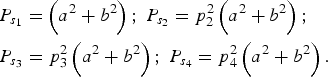
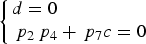
$$\eqalign{{A^2} & = {\left( {a{s_1} + b{p_2}{s_2} + a{\,p_3}{s_3} - b{p_4}{s_4} + c{p_5}{s_2}{s_3}{s_4} + d{p_6}{s_1}{s_3}{s_4} + c{p_7}{s_1}{s_2}{s_4} - d{p_8}{s_1}{s_2}{s_3}} \right)^2} \cr & \quad + {\left( { - b{s_1} + a{\,p_2}{s_2} + b{\,p_3}{s_3} + a{\,p_4}{s_4} - d{p_5}{s_2}{s_3}{s_4} + c{\,p_6}{s_1}{s_3}{s_4} + d{p_7}{s_1}{s_2}{s_4} + c{p_8}{s_1}{s_2}{s_3}} \right)^2} \cr & = \left( {{a^2} + {b^2}} \right)\left( {1 + p_2^2 + p_3^2 + p_4^2} \right) + \left( {{c^2} + {d^2}} \right)\left( {\,p_5^2 + p_6^2 + p_7^2 + p_8^2} \right) \cr & \quad + 2\left( {{\,p_4}{\,p_7} - {\,p_3}{\,p_8}} \right)\left( {ad - bc} \right){s_1}{s_2} \cr & \quad + \left( {2{\,p_3}\left( {{a^2} - {b^2}} \right) + 2{\,p_5}{\,p_7}\left( {{c^2} - {d^2}} \right) + 2\left( {{\,p_2}{\,p_8} + {\,p_4}{\,p_6}} \right)\left( {ac - bd} \right)} \right){s_1}{s_3} \cr & \quad + \left( {2\left( {bc + ad} \right)\left( {{\,p_3}{\,p_6} + {\,p_2}{\,p_7}} \right) - 4ab{p_4} - 4cd{p_5}{\,p_8}} \right){s_1}{s_4} \cr & \quad + 2\left( {ac + bd} \right)\left( {{\,p_5} + {\,p_3}{\,p_7} + {\,p_2}{\,p_6} + {\,p_4}{\,p_8}} \right){s_1}{s_2}{s_3}{s_4} \cr & \quad + 2\left( {ad - bc} \right)\left( {{\,p_6} - {\,p_2}{\,p_5}} \right){s_3}{s_4} \cr & \quad + \left( {2{\,p_2}{\,p_4}\left( {{a^2} - {b^2}} \right) + 2{\,p_6}{\,p_8}\left( {{c^2} - {d^2}} \right) + 2\left( {{\,p_7} + {\,p_3}{\,p_5}} \right)\left( {ac - bd} \right)} \right){s_2}{s_4} \cr & \quad + \left( {4ab{\,p_2}{\,p_3} + 4cd{\,p_6}{\,p_7} - 2\left( {bc + ad} \right)\left( {{\,p_8} + {\,p_4}{\,p_5}} \right)} \right){s_2}{s_3}} $$Since the values of s 1, s 2, s 3 and s 4 can be 1 or −1, envelope A may have 16 different values. To ensure A is constant in this sub-period, a simple idea is that A is unrelated to the four signal components. As a result, we set all the coefficients related with the signal components in Equation (6) to be zero, i.e.
 $$\left\{ \matrix{\left( {{\,p_4}{\,p_7} - {\,p_3}{\,p_8}} \right)\left( {ad - bc} \right) = 0 \hfill \cr {\,p_3}\left( {{a^2} - {b^2}} \right) + {\,p_5}{\,p_7}\left( {{c^2} - {d^2}} \right) + \left( {{\,p_2}{\,p_8} + {\,p_4}{\,p_6}} \right)\left( {ac - bd} \right) = 0 \hfill \cr \left( {bc + ad} \right)\left( {{\,p_3}{\,p_6} + {\,p_2}{\,p_7}} \right) - 2ab{\,p_4} - 2cd{\,p_5}{\,p_8} = 0 \hfill \cr \left( {ac + bd} \right)\left( {{\,p_5} + {\,p_3}{\,p_7} + {\,p_2}{\,p_6} + {\,p_4}{\,p_8}} \right) = 0 \hfill \cr \left( {ad - bc} \right)\left( {{\,p_6} - {\,p_2}{\,p_5}} \right) = 0 \hfill \cr {\,p_2}{\,p_4}\left( {{a^2} - {b^2}} \right) + {\,p_6}{\,p_8}\left( {{c^2} - {d^2}} \right) + \left( {{\,p_7} + {\,p_3}{\,p_5}} \right)\left( {ac - bd} \right) = 0 \hfill \cr 2ab{p_2}{\,p_3} + 2cd{p_6}{\,p_7} - \left( {bc + ad} \right)\left( {{\,p_8} + {\,p_4}{\,p_5}} \right) = 0 \hfill} \right.$$
Then A 2 is simplified as
 $${A^2} = \left( {{a^2} + {b^2}} \right)\left( {1 + p_2^2 + p_3^2 + p_4^2} \right) + \left( {{c^2} + {d^2}} \right)\left( {\,p_5^2 + p_6^2 + p_7^2 + p_8^2} \right)$$
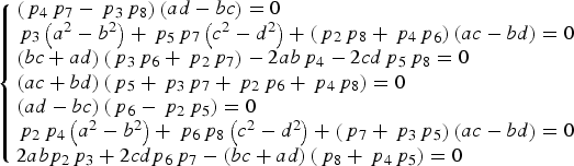
Equations (7) can ensure that the composite signal's envelope is constant in one sub-period. In order to keep the envelope A unchanged in other sub-periods, we have to choose carefully the values of a, b, c and d in other sub-periods; meanwhile the values p 5, p 6, p 7 and p 8 do not change. An interesting property of Equations (7) helps us reach the objective. We find that if {p 5, p 6, p 7, p 8, a, b, c, d} is a solution of Equations (7), it is easy to verify that the following Equations (9) and (10) are also the solutions of Equations (7).
 $$\left\{ {{\,p_5}\comma\ {\,p_6}\comma\ {\,p_7}\comma\ {\,p_8}\comma\ K \cdot a \comma\ K \cdot b \comma\ K \cdot c\comma\ K \cdot d} \right\}$$
 $$\eqalign{& \left\{ {{\,p_5}\comma\ {\,p_6}\comma\ {\,p_7}\comma\ {\,p_8}\comma\ b\comma\ a\comma\ d\comma\ c} \right\}\semicolon\ \cr & \left\{ {{\,p_5}\comma\ {\,p_6}\comma\ {\,p_7}\comma\ {\,p_8}\comma\ - a\comma\ b\comma\ - c\comma\ d} \right\}\semicolon\ \cr & \left\{ {{\,p_5}\comma\ {\,p_6}\comma\ {\,p_7}\comma\ {\,p_8}\comma\ a\comma\ - b\comma\ c\comma\ - d} \right\}.} $$
Note that K in Equation (9) can be an arbitrary real number; this means that we can set one of a, b, c and d to be an arbitrary real number. For example, let b = 1. Then there are only seven parameters to be solved. In particular, K = −1 means that a, b, c and d have an opposite sign simultaneously.
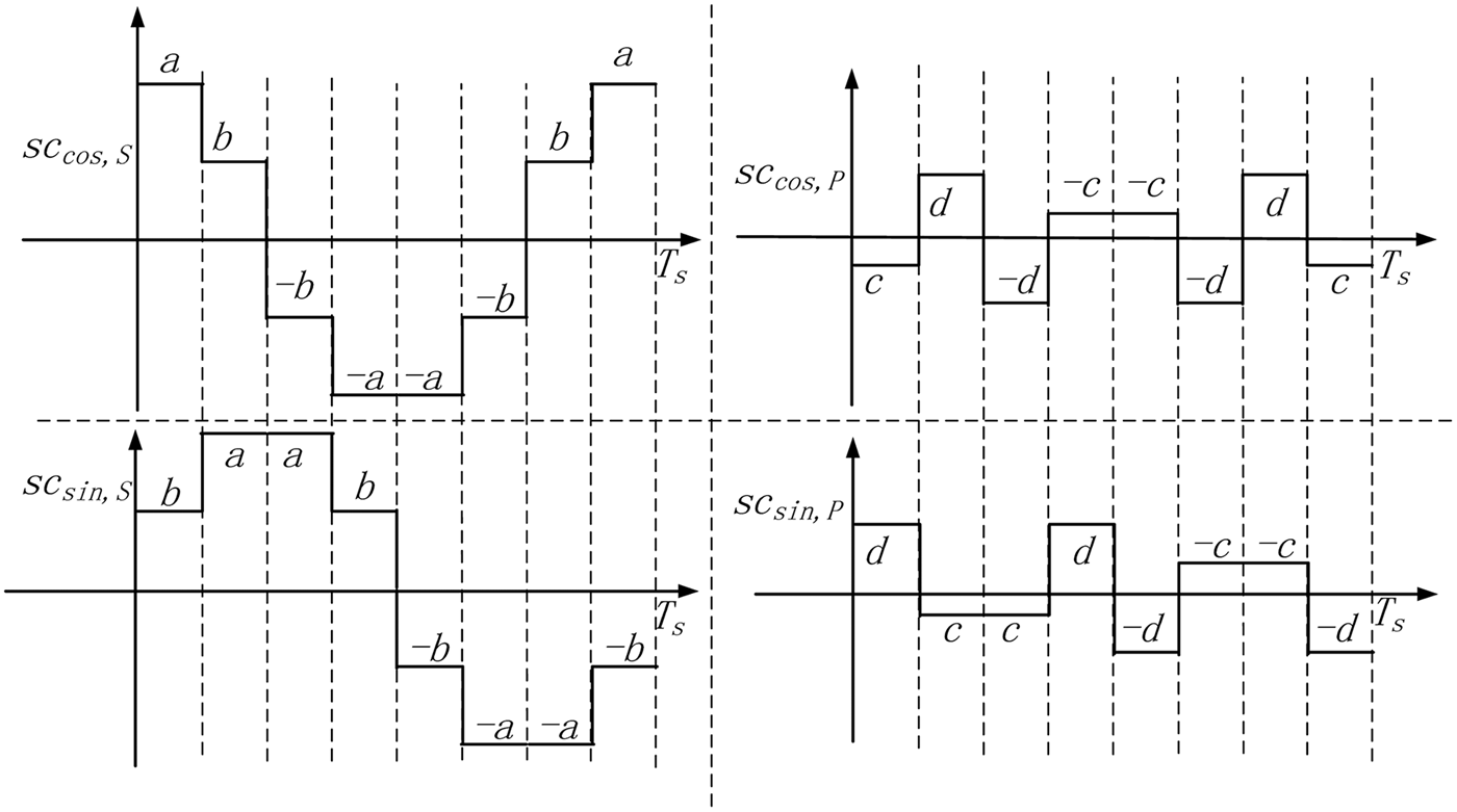
Each subcarrier period is sub-divided into eight equal sub-periods with reference to AltBOC modulation. When we obtain a solution of Equations (7), a, b, c and d become the subcarrier coefficients of the first sub-period. The parameters p 5, p 6, p 7 and p 8 are unchanged in the eight sub-periods. The subcarrier coefficients in the other sub-periods are set according to Equations (9) and (10), which are expressed as
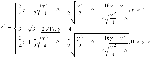
 $$\eqalign{& S{C_{\cos\!\comma\ S}} = \left\{ {a\comma\ b\comma\ -\! b\comma\ - \!a\comma\ - \!a\comma\ -\! b \comma\ b\comma\ a} \right\} \cr & S{C_{\sin\!\comma\ S}} = \left\{ {b\comma\ a\comma\ a\comma\ b\comma\ - \!b\comma\ - \!a\comma\ -\! a\comma\ -\! b} \right\} \cr & S{C_{\cos\!\comma\ P}} = \left\{ {c\comma\ d\comma\ - \!d\comma\ -\! c\comma\ -\! c\comma\ -\! d\comma\ d\comma\ c} \right\} \cr & S{C_{\sin\!\comma\ P}} = \left\{ {d\comma\ c\comma\ c\comma\ d\comma\ - \!d\comma\ - \!c\comma\ -\! c\comma\ - \!d} \right\}} $$
where SC cos,S and SC sin,S represent the eight coefficients for the subcarriers of the single signals. SC cos,P and SC sin,P represent the eight coefficients for the subcarriers of the product signals. Similar to AltBOC modulation, a period of subcarriers can be expressed as (Shivaramaiah and Dempster, Reference Shivaramaiah and Dempster2009):
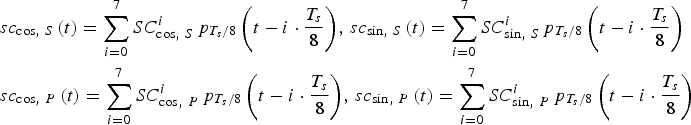 $$\eqalign{& s{c_{\cos\comma\ S}}\left( t \right) = \sum\limits_{i = 0}^7 {SC_{\cos\comma\ S}^i {\,p_{{{{T_s}} / 8}}}\left( {t - i \cdot \displaystyle{{{T_s}} \over 8}} \right)}\comma \,s{c_{\sin\comma\ S}}\left( t \right) = \sum\limits_{i = 0}^7 {SC_{\sin\comma\ S}^i {\,p_{{{{T_s}} / 8}}}\left( {t - i \cdot \displaystyle{{{T_s}} \over 8}} \right)} \cr & s{c_{\cos\comma\ P}}\left( t \right) = \sum\limits_{i = 0}^7 {SC_{\cos\comma\ P}^i {\,p_{{{{T_s}} / 8}}}\left( {t - i \cdot \displaystyle{{{T_s}} \over 8}} \right)}\comma \,s{c_{\sin\comma\ P}}\left( t \right) = \sum\limits_{i = 0}^7 {SC_{\sin\comma\ P}^i {\,p_{{{{T_s}} / 8}}}\left( {t - i \cdot \displaystyle{{{T_s}} \over 8}} \right)}} $$
where i represents the ith sub-period of subcarrier period, p Ts/8(t) is the rectangular function which is unity during 0 ⩽ t < T s/8 and zero elsewhere.
Figure 3 shows the schematic drawing of subcarriers in GAltBOC modulation. Because the subcarrier coefficients in Equation (11) are set according to Equations (9) and (10) in each sub-period, the envelope would always be constant in a period of the subcarrier functions. Equation (5) is the expression of GAltBOC modulation in the first sub-period of subcarrier period. By exploiting the subcarrier coefficients in Equation (11), the expressions of GAltBOC modulation in other sub-periods can be obtained. For example, the following equations show the expressions in the second and third sub-period of subcarrier period.
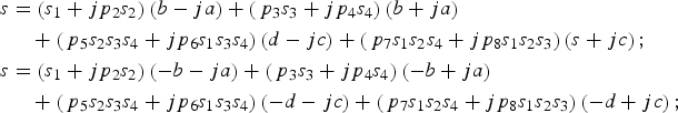 $$\eqalign{s & = \left( {{s_1} + j{p_2}{s_2}} \right)\left( {b - ja} \right) + \left( {{\,p_3}{s_3} + j{p_4}{s_4}} \right)\left( {b + ja} \right) \cr & \quad + \left( {{\,p_5}{s_2}{s_3}{s_4} + j{p_6}{s_1}{s_3}{s_4}} \right)\left( {d - jc} \right) + \left( {{\,p_7}{s_1}{s_2}{s_4} + j{p_8}{s_1}{s_2}{s_3}} \right)\left( {s + jc} \right)\semicolon\ \cr s & = \left( {{s_1} + j{p_2}{s_2}} \right)\left( { - b - ja} \right) + \left( {{\,p_3}{s_3} + j{p_4}{s_4}} \right)\left( { - b + ja} \right) \cr & \quad + \left( {{\,p_5}{s_2}{s_3}{s_4} + j{p_6}{s_1}{s_3}{s_4}} \right)\left( { - d - jc} \right) + \left( {{\,p_7}{s_1}{s_2}{s_4} + j{p_8}{s_1}{s_2}{s_3}} \right)\left( { - d + jc} \right)\semicolon\ } $$
Combining these expressions of eight sub-periods into a unified expression, our GAltBOC modulation can be written as the form of Equation (1), i.e.
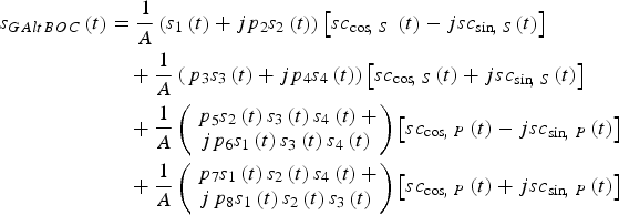 $$\eqalign{{s_{GAltBOC}}\left( t \right) & = \displaystyle{1 \over A}\left( {{s_1}\left( t \right) + j{p_2}{s_2}\left( t \right)} \right)\left[ {s{c_{\cos\!\comma\ S}}\ \left( t \right) - js{c_{\sin\!\comma\ S}}\left( t \right)} \right] \cr & \quad + \displaystyle{1 \over A}\left( {{\,p_3}{s_3}\left( t \right) + j{p_4}{s_4}\left( t \right)} \right)\left[ {s{c_{\cos\!\comma\ S}}\left( t \right) + js{c_{\sin\!\comma\ S}}\left( t \right)} \right] \cr & \quad + \displaystyle{1 \over A}\left( \matrix{{\,p_5}{s_2}\left( t \right){s_3}\left( t \right){s_4}\left( t \right) + \cr j{p_6}{s_1}\left( t \right){s_3}\left( t \right){s_4}\left( t \right)} \right)\left[ {s{c_{\cos\!\comma\ P}}\left( t \right) - js{c_{\sin\!\comma\ P}}\left( t \right)} \right] \cr & \quad + \displaystyle{1 \over A}\left( \matrix{{\,p_7}{s_1}\left( t \right){s_2}\left( t \right){s_4}\left( t \right) + \cr j{\,p_8}{s_1}\left( t \right){s_2}\left( t \right){s_3}\left( t \right)} \right)\left[ {s{c_{\cos\!\comma\ P}}\left( t \right) + js{c_{\sin\!\comma\ P}}\left( t \right)} \right]} $$
where 1/A is used to normalise the power of s GAltBOC(t).
Figure 3. Schematic drawing of the subcarriers in GAltBOC modulation.
Now we need to determine whether Equations (7) have a non-trivial solution. Fortunately, for any PAR, namely when p 2, p 3, and p 4 are given, we can find a special solution, i.e.
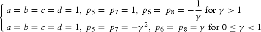
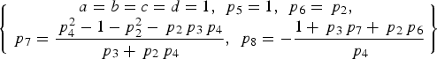 $$\left\{ \matrix{ a = b = c = d = 1\comma\ {\,p_5} = 1\comma\ {\,p_6} = {\,p_2}\comma\ \cr {\,p_7} = \displaystyle{{\,p_4^2 - 1 - p_2^2 - {\,p_2}{\,p_3}{\,p_4}} \over {{\,p_3} + {\,p_2}{\,p_4}}}\comma\ {\,p_8} = - \displaystyle{{1 + {\,p_3}{\,p_7} + {\,p_2}{\,p_6}} \over {{\,p_4}}}} \right\}$$
Substituting Equation (14) into Equations (7), it is easy to verify that Equation (14) is the solution of Equations (7). It is noted that when a = b = c = d = 1, the subcarriers defined by Equation (12) become the binary square wave subcarriers with cosine phasing or sine phasing, which are also adopted in TD-AltBOC modulation (Tang et al., Reference Tang, Zhou, Wei, Yan, Liu, Ran and Zhou2011) and TMOC-QPSK modulation (Shivaramaiah and Dempster, Reference Shivaramaiah and Dempster2013).
Since the power provided by the satellite payload is limited, we expect that the combination efficiency is as high as possible. The combination efficiency is defined as the total useful signal power divided by the total power transmitted (Fan et al., Reference Fan, Lin, Wang and Dafesh2008). For the GAltBOC modulation, the combination efficiency η is expressed as
 $$\eta = \displaystyle{{{P_{{s_1}}} + {P_{{s_2}}} + {P_{{s_3}}} + {P_{{s_4}}}} \over {{A^2}}} = \displaystyle{{\left( {{a^2} + {b^2}} \right)\left( {1 + p_2^2 + p_3^2 + p_4^2} \right)} \over {{A^2}}} \times 100 \% $$
where A 2 is defined by Equation (8). The solution that can maximise the combination efficiency η is referred to as the optimal solution of Equations (7). Generally speaking, the particular solution Equation (14) is not always the optimal solution.
For an arbitrary PAR, it is generally difficult to solve the analytical expression of the optimal solution. However, the optimal solution can be obtained by numerical methods. The above problem is a nonlinear optimisation problem with constraints of Equations (7). The objective to maximise the combination efficiency is equivalent to minimising 1 − η (Zhang et al., Reference Zhang, Zhou and Wang2011). The constrained optimisation problem is expressed as
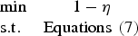 $$\matrix{{\rm min} & 1 - \eta \cr {{\rm s.}{\rm t.}} \hfill & {\rm Equations} \ \left(7 \right)} $$
In the subsequent section, we provide the optimal numerical solutions as an example for several PAR schemes. In order to obtain these optimal numerical solutions, the above constrained optimisation problem is firstly converted into an unconstrained optimisation problem by using the positive penalty function method (Dafesh and Cahn, Reference Dafesh and Cahn2009), and then the optimal numerical solution is found through the quasi-Newton method (Jasbir, Reference Jasbir2004).
2.4. The Power Spectrum Density (PSD) of GAltBOC
Comparing Equation (1) with Equation (13), it can be observed that GAltBOC modulation has a similar expression to AltBOC modulation. Thus the PSD of GAltBOC modulation can be obtained referring to the derivation of AltBOC's PSD. The detailed derivation process has been provided by Rebeyrol et al. (Reference Rebeyrol, Macabiau, Lestarquit, Ries, Issler, Boucheret and Bousquet2005) and Yarlykov (Reference Yarlykov2012). The frequency of subcarrier is f s. s 1, s 2, s 3 and s 4 are binary PRN code signals with chip rate R c. After a simple derivation, we can obtain the normalised PSD expression of GAltBOC modulation, that is
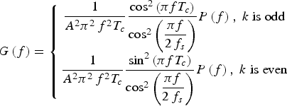 $$G\left( f \right) = \left\{ \matrix{\displaystyle{1 \over {{A^2}{\pi ^2}{\,f^2}{T_c}}}\displaystyle{{{{\cos} ^2}\left( {\pi f{T_c}} \right)} \over {{{\cos} ^2}\left( {\displaystyle{{\pi f} \over {2{\,f_s}}}} \right)}}P\left( f \right)\comma\ k\;{\rm is \;odd} \cr \displaystyle{1 \over {{A^2}{\pi ^2}{\,f^2}{T_c}}}\displaystyle{{{{\sin} ^2}\left( {\pi f{T_c}} \right)} \over {{{\cos} ^2}\left( {\displaystyle{{\pi f} \over {2{\,f_s}}}} \right)}}P\left( f \right)\comma\ k\;{\rm is \;even}} \right.$$
where k = 2*f s/R c is the modulation index, T c = 1/R c is the chip period. P(f) is given by
$$\eqalign{& P(f) =\cr & \quad \left({\matrix{\left( {\left( {1 + p_2^2 + p_3^2 + p_4^2} \right)\left( {{a^2} - {b^2}} \right) + \left( {\,p_5^2 + p_6^2 + p_7^2 + p_8^2} \right)\left( {{c^2} - {d^2}} \right)} \right){\cos ^2}\left( {\displaystyle{{\pi f} \over {2{\,f_s}}}} \right)+ \hfill \cr - 2\left( {\left( {1 + p_2^2 + p_3^2 + p_4^2} \right)\left( {{a^2} - {b^2}} \right) + \left( {\,p_5^2 + p_6^2 + p_7^2 + p_8^2} \right)\left( {{c^2} - {d^2}} \right)} \right)\cos \left( {\displaystyle{{\pi f} \over {2{\,f_s}}}} \right)\cos \left( {\displaystyle{{\pi f} \over {4{\,f_s}}}} \right)\hfill \cr - 2\left( {\left( {1 + p_2^2 + p_3^2 + p_4^2} \right)ab + \left( {\,p_5^2 + p_6^2 + p_7^2 + p_8^2} \right)cd} \right)\cos \left( {\displaystyle{{\pi f} \over {2{\,f_s}}}} \right)\hfill \cr + 4\left( {\left( {1 + p_2^2 + p_3^2 + p_4^2} \right)b\left( {a - b} \right) + \left( {\,p_5^2 + p_6^2 + p_7^2 + p_8^2} \right)d\left( {c - d} \right)} \right)\cos \left( {\displaystyle{{\pi f} \over {4{\,f_s}}}} \right)\hfill\cr + \left( {\left( {1 + p_2^2 - p_3^2 - p_4^2} \right)ab + \left( {\,p_5^2 + p_6^2 - p_7^2 - p_8^2} \right)cd} \right)\sin \left( {\displaystyle{{\pi f} \over {{\,f_s}}}} \right) \hfill \cr + \left( {\left( {1 + p_2^2 - p_3^2 - p_4^2} \right){{\left( {a - b} \right)}^2} + \left( {\,p_5^2 + p_6^2 - p_7^2 - p_8^2} \right){{\left( {c - d} \right)}^2}} \right)\sin \left( {\displaystyle{{3\pi f} \over {4{\,f_s}}}} \right)\hfill\cr \left( {\left( {1 + p_2^2 - p_3^2 - p_4^2} \right)\left( {{a^2} - 2ab + 3{b^2}} \right) + \left( {\,p_5^2 + p_6^2 - p_7^2 - p_8^2} \right)\left( {{c^2} - 2cd + 3{d^2}} \right)} \right)\sin \left( {\displaystyle{{\pi f{T_s}} \over 2}} \right)\hfill\cr \left( {\left( {1 + p_2^2 - p_3^2 - p_4^2} \right)\left( {{a^2} + 2ab - 3{b^2}} \right) + \left( {\,p_5^2 + p_6^2 - p_7^2 - p_8^2} \right)\left( {{c^2} + 2cd - 3{d^2}} \right)} \right)\sin \left( {\displaystyle{{\pi f} \over {4{\,f_s}}}} \right)\hfill \cr + \left( {\left( {1 + p_2^2 + p_3^2 + p_4^2} \right)\left( {{a^2} - 2ab + 3{b^2}} \right) + \left( {\,p_5^2 + p_6^2 + p_7^2 + p_8^2} \right)\left( {{c^2} - 2cd + 3{d^2}} \right)} \right)\hfill} } \right)}$$The PSD of GAltBOC modulation is verified in Section 5.
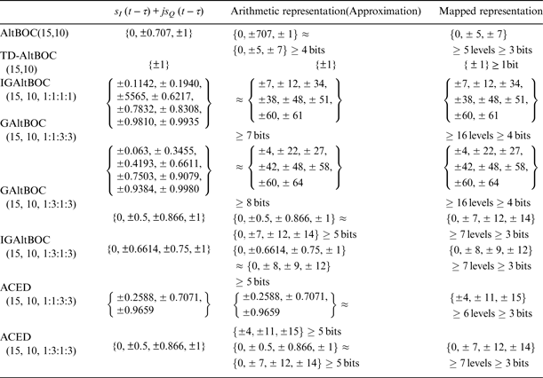
For clarity, the GAltBOC modulation is denoted as GAltBOC(m,n,r), where r represents the PAR of four signal components. m and n have the same meanings as those in AltBOC(m,n) (Rebeyrol et al., Reference Rebeyrol, Macabiau, Lestarquit, Ries, Issler, Boucheret and Bousquet2005), where m represents the ratio of the subcarrier frequency f s to 1·023 MHz, and n represents the ratio of the code rate R c to 1·023 MHz.
3. SEVERAL SPECIAL CASES
For any PAR scheme, Equations (7) have the analytical solution Equation (14), and then the corresponding GAltBOC modulation can be obtained by substituting Equation (14) into Equation (13). Actually, only some special PAR schemes are valuable. In particular, the power ratio between data component and pilot component in the same sideband should be designed carefully. In general, the power ratio between data component and pilot component is 1:1, such as the Galileo E1OS, E6CS and E5 signals (Galileo OS SIS ICD, 2010). However, for GPS L1C signal, 75% of power is allocated to the pilot component for enhanced signal tracking (Betz et al., Reference Betz, Blanco, Chan, Dafesh, Hegarty, Hudnut, Kasemsri, Keegan, Kovach, Lenahan, Ma, Rushanan, Sklar, Stansell, Wang and Yi2007). Namely, the power ratio between data component and pilot component is 1:3 for L1C signal. In this section, we analyse three special cases, which have been discussed by Yao and Lu (Reference Yao and Lu2013a). Additionally, the general cases are briefly discussed.
3.1. Case One
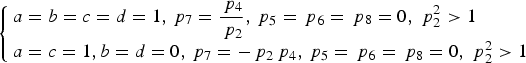
In this case, we consider that the power ratio between the data component and pilot component in the same sideband is 1:1, but the total power ratio between the lower sideband and upper sideband is 1: γ 2, where parameter γ is an adjustable positive real number. Thus, p 2 = 1, p 3 = p 4 = γ. The PAR of the four signal components is  $r = {P_{{s_1}}}:{P_{{s_2}}}:{P_{{s_3}}}:{P_{{s_4}}} = 1:1:{\gamma ^2}:{\gamma ^2}$. The significance of this case is that we can reallocate the power of a sideband service signal to another sideband service signal when required.
In this case, when γ 2 = 1, the four signal components have the same power, which corresponds to AltBOC modulation. Comparing Equation (13) with Equation (1), we can see that when the PAR is 1:1:1:1, one solution of Equations (7) can be expressed as
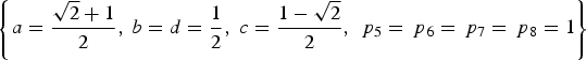 $$\left\{ {a = \displaystyle{{\sqrt 2 + 1} \over 2}\comma\ b = d = \displaystyle{1 \over 2}\comma\ c = \displaystyle{{1 - \sqrt 2} \over 2}\comma\ {\,p_5} = {\,p_6} = {\,p_7} = {\,p_8} = 1} \right\}$$
The fourth equation in Equations (7) is (ac + bd)(p 5 + p 3p 7 + p 2p 6 + p 4p 8) = 0. The AltBOC modulation shows that ac + bd = 0 for Case One. Namely, a/b = −d/c. Referring to the subcarrier coefficients of AltBOC modulation in Figure 1, we have
 $$ac + bd = 0 \; \displaystyle{a \over b} = - \displaystyle{d \over c} = \sqrt 2 + 1$$
For simplicity, we can set b = 1 according to Equation (9), then  $a = \sqrt 2 + 1$. Substituting Equation (19) into Equations (7), Equations (7) can be simplified as:
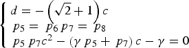 $$\left\{ {\matrix{d = - \left( {\sqrt 2 + 1} \right)c \hfill \cr {\,p_5} = {\,p_6} {\,p_7} = {\,p_8} \hfill \cr {\,p_5}{\,p_7}{c^2} - \left( {\gamma {\,p_5} + {\,p_7}} \right)c - \gamma = 0 \hfill}} \right.$$
Substituting Equation (20) into Equation (16), the optimisation problem Equation (16) is transformed into
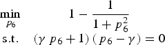
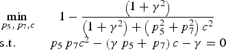 $$\matrix{{\mathop {\min }\limits_{{\,p_5}\comma{\,p_7}\comma c} \hfill } & {1 - \displaystyle{{\left( {1 + {\gamma ^2}} \right)} \over {\left( {1 + {\gamma ^2}} \right) + \left( {\,p_5^2 + p_7^2 } \right){c^2}}}} \cr {{\rm s}{\rm .t}{\rm .}}\hfill & {{\,p_5}{\,p_7}{c^2} - \left( {\gamma {\,p_5} + {\,p_7}} \right)c - \gamma = 0} \cr } $$
The objective function is equivalent to minimising 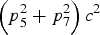 $\left( {p_5^2 + p_7^2} \right){c^2}$. Let X = p 5c, Y = p 7c, we can derive that X = (Y + γ)/(Y − γ). The above optimisation equation is simplified as
 $$\mathop {\min} \limits_Y{\rm f} \left( Y \right) = \displaystyle{{{{\left( {Y + \gamma} \right)}^2}} \over {{{\left( {Y - \gamma} \right)}^2}}} + {Y^2}$$
Calculate the first derivation of f(Y) and set it to zero, we have
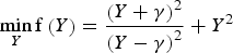
 $${Y^4} - 3\gamma {Y^3} + 3{\gamma ^2}{Y^2} - \left( {2\gamma + {\gamma ^3}} \right)Y - 2{\gamma ^2} = 0$$
The negative real number root Y* of Equation (22) is our desired solution. Y* can be calculated by
 $${Y^ {^\ast}} = \left\{ \matrix{\displaystyle{3 \over 4}\gamma - \displaystyle{1 \over 2}\sqrt {\displaystyle{{{\gamma ^2}} \over 4} + \Delta} - \displaystyle{1 \over 2}\sqrt {\displaystyle{{{\gamma ^2}} \over 2} - \Delta - \displaystyle{{16\gamma - {\gamma ^3}} \over {4\sqrt {\displaystyle{{{\gamma ^2}} \over 4} + \Delta}}}}\comma \gamma \gt 4 \hfill \cr 3 - \sqrt {3 + 2\sqrt {17}}\comma \gamma = 4 \hfill \cr \displaystyle{3 \over 4}\gamma + \displaystyle{1 \over 2}\sqrt {\displaystyle{{{\gamma ^2}} \over 4} + \Delta} - \displaystyle{1 \over 2}\sqrt {\displaystyle{{{\gamma ^2}} \over 2} - \Delta + \displaystyle{{16\gamma - {\gamma ^3}} \over {4\sqrt {\displaystyle{{{\gamma ^2}} \over 4} + \Delta}}}}\comma 0 \lt \gamma \lt 4 \hfill} \right.$$
where
 $$\Delta = \displaystyle{{\root 3 \of {{\Delta _1}}} \over 3} - \displaystyle{{14{\gamma ^2}} \over {\root 3 \of {{\Delta _1}}}}\comma {\Delta _1} = - 54{\gamma ^4} + 54{\gamma ^2} + 6{\gamma ^2}\sqrt {81{\gamma ^4} + 1896{\gamma ^2} + 81} $$
Let d = 1, then the desired solution of Equations (7) for Case One is
 $$\left\{ {a = \sqrt 2 + 1\comma b = d = 1\comma c = 1 - \sqrt 2\comma {\,p_7} = {\,p_8} = \displaystyle{{{Y^ {\ast}}} \over c}{\comma} {\,p_5} = {\,p_6} = \displaystyle{{{Y^ {\ast}} + \gamma} \over {c\left( {{Y^ {\ast}} - \gamma} \right)}}} \right\}$$
3.1.1. Combination efficiency for Case One
Substituting Equation (24) into Equation (15), we can obtain the combination efficiencies of the theoretical solutions versus γ 2, which are shown in Figure 4. For Case One, γ 2 represents the total power ratio between the upper sideband and lower sideband. This clearly illustrates that the power difference between the lower sideband and upper sideband is greater and the combination efficiency is higher. Moreover, when γ 2 = 1, it corresponds to the AltBOC modulation, and it has the lowest combination efficiency in Case One.
Figure 4. Combination efficiency for Case One vs power ratio γ 2.
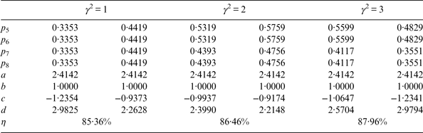
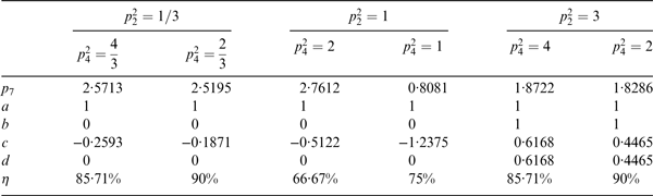
As a comparison, we also show the combination efficiencies of the numerical optimal solutions versus γ 2. The numerical optimal solutions are obtained by solving the optimisation problem Equation (16). The quasi-Newton method is used, and the convergence condition of the quasi-Newton method is that the norm of the gradient vector is smaller than 10−6 (Jasbir, Reference Jasbir2004). We show several optimal numerical solutions as examples in Table 1. For each γ 2, we list two optimal numerical solutions. Let b = 1 according to Equation (9) before the optimisation process. For a given PAR, we can see that the numerical optimal solution is not unique, but the combination efficiency of numerical optimal solutions is unique.
Table 1. Examples of numerical optimal solution for Case One.
It can be observed from Figure 4 that the theoretical solution Equation (24) can reach the optimal combination efficiency. Thus Equation (24) is the theoretical optimal solution for Case One.
3.1.2. PSD properties of subcarriers for Case One
As shown in Equation (13), the complex subcarriers are used. The four complex subcarriers are defined as
 $$\eqalign{& s{c_{L\comma S}}\left( t \right) = s{c_{\cos\!\comma S}}\left( t \right) - js{c_{\sin\!\comma S}}\left( t \right)\comma \cr & s{c_{U\!\comma S}}\left( t \right) = s{c_{\cos\!\comma S}}\left( t \right) + js{c_{\sin\!\comma S}}\left( t \right)\comma \cr & s{c_{L\comma P}}\left( t \right) = s{c_{\cos\!\comma P}}\left( t \right) - js{c_{\sin\!\comma P}}\left( t \right)\comma \cr & s{c_{U\!\comma P}}\left( t \right) = s{c_{\cos\!\comma P}}\left( t \right) + js{c_{\sin\!\comma P}}\left( t \right)} $$
The four complex subcarriers are called the Single Side Band (SSB) sub-carriers (Lestarquit et al., Reference Lestarquit, Artaud and Issler2008).
In Case One, a = 2·414, b = d = 1, c = −0·4142. Therefore, the SSB subcarriers are equivalent to those subcarriers of AltBOC modulation. Figure 5 shows the PSD of four SSB subcarriers in Equation (25). The horizontal axis is the ratio of harmonic frequency to the subcarrier's frequency f s. The vertical axis is the power ratio of each harmonic to the total sub-carrier power, expressed in %. sc L,S(t) is used to shift the frequency of s 1 and s 2 to the lower sideband, and sc U,S(t) is used to shift the frequency of s 3 and s 4 to the upper sideband. We can see that 94·96% of the total power is located at +f s for sc U,S(t) and −f s for sc L,S(t) (Lestarquit et al., Reference Lestarquit, Artaud and Issler2008). sc L,P(t) and sc U,P(t) are the complex subcarriers for the product signals, the main power of sc L,P(t) and sc U,P(t) are at −3f s and 3f s respectively, which means the product signals have their main lobes at −3f s or 3f s.
Figure 5. The PSD of four complex subcarriers for Case One.
3.1.3. Phase LUT for Case One
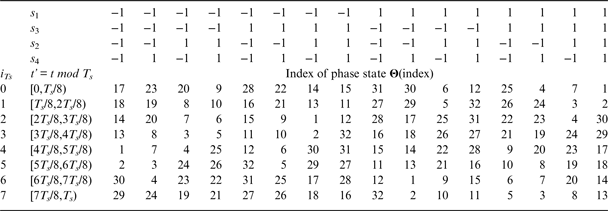
GAltBOC modulation can be implemented according to the baseband Equation (13). In addition, the GAltBOC modulation can also be generated by LUT. For Case One, each subcarrier is sub-divided into eight equal sub-periods. The combinations of s 1, s 2, s 3 and s 4 have 16 different values. Therefore, the LUT is an 8 × 16 two-dimensional table, which is similar to the one of AltBOC (Galileo OS SIS ICD, 2010). Referring to the method of Yao and Lu (Reference Yao and Lu2013b), the phase state of GAltBOC modulation is calculated by
 $${\rm Angle}\ \left( {{s_{GAltBOC}}\left( t \right)} \right) = {\rm atan}\; 2\left( {{\mathop{\rm Im}\nolimits} \left( {{s_{GAltBOC}}\left( t \right)} \right)\comma{\mathop{\rm Re}\nolimits} \left( {{s_{GAltBOC}}\left( t \right)} \right)} \right)$$
where Re(s GAltBOC(t)) and Im(s GAltBOC(t)) represent the real part and imaginary part of s GAltBOC(t) respectively. atan2(·) is the four quadrant arctangent function.
Substituting Equations (13) and (24) into Equation (26), we can obtain the LUT of Case One. The results show that there are only 32 different phase values in the LUT. In other words, the total number of phase points in the constellation is 32 for Case One. For clarity, these 32 phase values form a 1 × 32 row vector Θ. Θ is given by
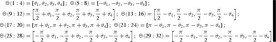 $$\eqalign{{\bf \Theta} (1:4) & = \left[ {{\theta _1}\comma{\theta _2}\comma{\theta _3}\comma{\theta _4}} \right]\semicolon \;{\bf \Theta} (5:8) = \left[ { - {\theta _1}\comma - {\theta _2}\comma - {\theta _3}\comma - {\theta _4}} \right]\semicolon \cr {\bf \Theta} (9:12) & = \left[ {\displaystyle{\pi \over 2} + {\theta _1}\comma \displaystyle{\pi \over 2} + {\theta _2}\comma\displaystyle{\pi \over 2} + {\theta _3}\comma\displaystyle{\pi \over 2} + {\theta _4}} \right]\semicolon \;{\bf \Theta} (13:16) = \left[ {\displaystyle{\pi \over 2} - {\theta _1}\comma\displaystyle{\pi \over 2} - {\theta _2}\comma\displaystyle{\pi \over 2} - {\theta _3}\comma\displaystyle{\pi \over 2} - {\theta _4}} \right]\semicolon \cr {\bf \Theta} (17:20) & = \left[ {\pi + {\theta _1}\comma\pi + {\theta _2}\comma\pi + {\theta _3}\comma\pi + {\theta _4}} \right]\semicolon \;{\bf \Theta} (21:24) = \left[ {\pi - {\theta _1}\comma\pi - {\theta _2}\comma\pi - {\theta _3}\comma\pi - {\theta _4}} \right]\semicolon \cr {\bf \Theta} (25:28) & = \left[ { - \displaystyle{\pi \over 2} + {\theta _1}\comma - \displaystyle{\pi \over 2} + {\theta _2}\comma - \displaystyle{\pi \over 2} + {\theta _3}\comma - \displaystyle{\pi \over 2} + {\theta _4}} \right]\semicolon\;{\bf \Theta} (29:32) = \left[ { - \displaystyle{\pi \over 2} - {\theta _1}\comma - \displaystyle{\pi \over 2} - {\theta _2}\comma - \displaystyle{\pi \over 2} - {\theta _3}\comma - \displaystyle{\pi \over 2} - {\theta _4}} \right]} $$
where
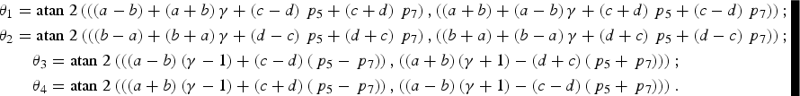 $$\eqalign{& {\theta _1} = {\rm atan} \;2\left( {\left( {\left( {a - b} \right) + \left( {a + b} \right)\gamma + \left( {c - d} \right){\,p_5} + \left( {c + d} \right){\,p_7}} \right),\left( {\left( {a + b} \right) + \left( {a - b} \right)\gamma + \left( {c + d} \right){\,p_5} + \left( {c - d} \right){\,p_7}} \right)} \right)\semicolon \cr & {\theta _2} = {\rm atan} \;2\left( {\left( {\left( {b - a} \right) + \left( {b + a} \right)\gamma + \left( {d - c} \right){\,p_5} + \left( {d + c} \right){\,p_7}} \right),\left( {\left( {b + a} \right) + \left( {b - a} \right)\gamma + \left( {d + c} \right){\,p_5} + \left( {d - c} \right){\,p_7}} \right)} \right)\semicolon \cr & \quad\quad{\theta _3} = {\rm atan}\; 2\left( {\left( {\left( {a - b} \right)\left( {\gamma - 1} \right) + \left( {c - d} \right)\left( {{\,p_5} - {\,p_7}} \right)} \right)\comma\left( {\left( {a + b} \right)\left( {\gamma + 1} \right) - \left( {d + c} \right)\left( {{\,p_5} + {\,p_7}} \right)} \right)} \right)\semicolon \cr & \quad\quad{\theta _4} = {\rm atan}\; 2\left( {\left( {\left( {a + b} \right)\left( {\gamma - 1} \right) + \left( {c + d} \right)\left( {{\,p_5} - {\,p_7}} \right)} \right)\comma\left( {\left( {a - b} \right)\left( {\gamma + 1} \right) - \left( {c - d} \right)\left( {{\,p_5} + {\,p_7}} \right)} \right)} \right).} $$
 For example, when γ 2 = 3, we have  ${\theta _1} = 0\cdot85\left( {{\rm rad}} \right) = 48\cdot 61\left( {\deg} \right)$,
 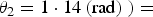 ${\theta_2} = 1 \cdot 14 \left({\rm rad} \right)\left. \right) =$
 $65\cdot21\left( {\deg} \right)$,
  ${\theta _3} = 0\cdot06\left( {{\rm rad}} \right) = 3\cdot61\left( {\deg} \right)$ and
  ${\theta _4} = 0\cdot35\left( {{\rm rad}} \right) = 20\cdot21\left( {\deg} \right)$. Note that we can have the operation that Θ modulo 2π, and then these phase values would belong to the region of [0, 2π). These phase values in the LUT can be represented by the index of phase state Θ (Zhang et al., Reference Zhang, Yao and Lu2014). For Case One, the general phase LUT is presented in Table 2.
Table 2. Phase LUT for Case One.
3.2. Case Two
In this case, we consider that the power of lower sideband and upper sideband are the same, but the power ratio between the data component and pilot component in the same sideband is 1:γ 2, where parameter γ is an adjustable positive real number. Namely, p 3 = 1, p 2 = p 4 = γ, and γ ≠ 1. The PAR of the four signal components is  $r = {P_{{s_1}}}:{P_{{s_2}}}:{P_{{s_3}}}:{P_{{s_4}}} = 1:{\gamma ^2}:1:{\gamma ^2}$. The significance of Case Two is that we can allocate more power to the pilot component when the total power of one sideband is limited, which can enhance the signal tracking (Betz et al., Reference Betz, Blanco, Chan, Dafesh, Hegarty, Hudnut, Kasemsri, Keegan, Kovach, Lenahan, Ma, Rushanan, Sklar, Stansell, Wang and Yi2007).
Considering that s 1 and s 3 are equivalent, and s 2 and s 4 are also equivalent, the product signals s 2(t)s 3(t)s 4(t) and s 1(t)s 2(t)s 4(t) are equivalent, and the product signals s 1(t)s 3(t)s 4(t) and s 1(t)s 2(t)s 3(t) are equivalent. Therefore, we have p 5 = p 7 and p 6 = p 8. According to Equation (24), the subcarriers of Case One are not applicable to Case Two. So we can select the binary subcarrier in Equation (14). Namely, a = b = c = d = 1. Then Equations (7) can be simplified as:
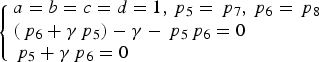 $$\left\{ \matrix{a = b = c = d = 1\comma{\,p_5} = {\,p_7}\comma{\,p_6} = {\,p_8} \hfill \cr \left( {{\,p_6} + \gamma {\,p_5}} \right) - \gamma - {\,p_5}{\,p_6} = 0 \hfill \cr {\,p_5} + \gamma {\,p_6} = 0 \hfill} \right.$$
p 5 = −γp 6. Substituting Equation (27) into Equation (16), the optimisation problem Equation (16) is transformed into
 $$\matrix{{\mathop {\min }\limits_{{\,p_6}} \hfill } & {1 - \displaystyle{1 \over {1 + p_6^2 }}} \cr {{\rm s}{\rm .t}{\rm .} \hfill } & {\left( {\gamma {\,p_6} + 1} \right)\left( {{\,p_6} - \gamma } \right) = 0} \cr } $$
The optimal solution of Equation (28) is
 $$\left\{ \matrix{{\,p_6} = - \displaystyle{1 \over \gamma} \;{\rm for} \;\gamma \gt 1 \hfill \cr {\,p_6} = \gamma \;{\rm for \;0} \le \gamma \lt 1 \hfill} \right.$$
Then the solution of Equations (7) in this case is:
 $$\left\{ \matrix{a = b = c = d = 1\comma{\,p_5} = {\,p_7} = 1\comma{\,p_6} = {\,p_8} = - \displaystyle{1 \over \gamma} \;{\rm for} \;\gamma \gt 1 \hfill \cr a = b = c = d = 1\comma{\,p_5} = {\,p_7} = - {\gamma ^2}\comma{\,p_6} = {\,p_8} = \gamma \;{\rm for \;0} \le \gamma \lt 1 \hfill} \right.$$
3.2.1. Combination efficiency for Case Two
Substituting Equation (30) into Equation (15), we can obtain the combination efficiency of Case Two, which is given by
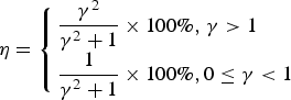 $$\eta = \left\{ \matrix{\displaystyle{{{\gamma ^2}} \over {{\gamma ^2} + 1}} \times {\rm 100\%\comma} \;\gamma \gt 1 \hfill \cr \displaystyle{1 \over {{\gamma ^2} + 1}} \times {\rm 100\%\comma 0} \le \gamma \lt 1 \hfill} \right.$$
For Case Two, γ 2 represents the power ratio between the pilot component and data component in the same sideband.
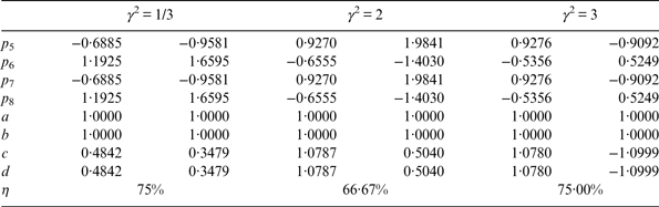
According to Equation (31), we show the combination efficiencies of theoretical solutions versus γ 2 in Figure 6. The combination efficiencies of the numerical optimal solutions are also shown in Figure 6. Equation (31) and Figure 6 clearly illustrate that the greater the power difference between data component and pilot component, the higher the combination efficiency. In particular, when γ 2 = 0, it means that only the data components at the lower and upper sideband are combined. When γ 2 → ∞, it means that only the pilot components at the lower and upper sideband are combined. The combination efficiencies of the two special examples are 100%.
Figure 6. Combination efficiency for Case Two vs power ratio γ 2.
The numerical optimal solutions in Figure 6 are obtained by solving the optimisation problem Equation (16). As examples, we show several numerical optimal solutions in Table 3. Figure 6 clearly shows that the theoretical solution Equation (30) can reach the optimal combination efficiency. Thus, Equation (30) is the theoretical optimal solution for Case Two.
Table 3. Examples of numerical optimal solutions for Case Two.
3.2.2. PSD properties of subcarriers for Case Two
Since a = b = c = d = 1, the SSB sub-carriers in Equation (25) become the binary complex subcarrier. Similar to the earlier case, we show the PSD of sub-carriers of Case Two in Figure 7. We can see that 81·06% of the total power is located at +f s for sc U,S(t) and −f s for sc L,S(t) (Lestarquit et al., Reference Lestarquit, Artaud and Issler2008). Moreover, the product signals also have their main lobes at +f s or −f s in Case Two.
Figure 7. The PSD of four complex subcarriers for Case Two.
3.2.3. Phase LUT for Case Two
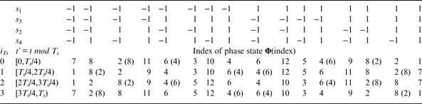
Each binary subcarrier of Case Two is sub-divided into four equal sub-periods. Therefore, the LUT is a 4 × 16 two-dimensional table for Case Two. Substituting Equations (13) and (30) into Equation (26), we can derive the LUT. The results show that there are only 12 different phase values in the LUT. Namely, the total number of phase points in the constellation is 12 for Case Two. These 12 phase values form a 1 × 12 row vector Φ. Φ is given by
 $${\bf \Phi} = \left[ {{\varphi _1}\comma0\comma\displaystyle{\pi \over 2} + {\varphi _1}\comma\displaystyle{\pi \over 2}\comma - \displaystyle{\pi \over 2} + {\varphi _1}\comma - \displaystyle{\pi \over 2}\comma\pi + {\varphi _1}\comma \pi\comma - {\varphi _1}\comma\displaystyle{\pi \over 2} - {\varphi _1}\comma\pi - {\varphi _1}\comma - \displaystyle{\pi \over 2} - {\varphi _1}} \right]\semicolon$$
where
 $$\varphi = {\rm atan}\; 2\left( {\left( {\gamma + {\,p_6}} \right)\comma\left( {1 + {\,p_5}} \right)} \right)$$
For example, when γ 2 = 3, we have  $\varphi = {\pi / 6}\left( {{\rm rad}} \right) = 30\left( {\deg} \right)$. Using the index of phase state Φ, the general phase LUT for Case Two is listed in Table 4. When γ < 1, a part of these indices should be replaced by those in the parentheses.
Table 4. Phase LUT for Case Two.
3.3. Case Three
In this case, one signal component can be cancelled, and then only three signals are combined. With no loss of generality, let the power of s 3(t) be zero, namely p 3 = 0. The significance of Case Three is that we can cancel the data component in the upper sideband when required, and even reallocate its power to the pilot component in the upper sideband. Since s 3(t) is cancelled, the product signals related with s 3 in Equation (4) do not exist. Thus, we have p 5 = p 6 = p 8 = 0. Set a = 1 according to Equation (9), then Equations (7) are simplified as
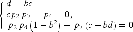
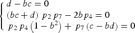 $$\left\{ \matrix{d - bc = 0 \hfill \cr \left( {bc + d} \right){\,p_2}{\,p_7} - 2b{p_4} = 0 \hfill \cr {\,p_2}{\,p_4}\left( {1 - {b^2}} \right) + {\,p_7}\left( {c - bd} \right) = 0 \hfill} \right.$$
Equations (32) can be decomposed into two sub-equations according to the value of b. When b = 0, Equations (32) are rewritten as
 $$\left\{ \matrix{d = 0 \hfill \cr {\,p_2}{\,p_4} + {\,p_7}c = 0 \hfill} \right.$$
Substituting Equations (33) into Equation (15), the combination efficiency when b = 0 is
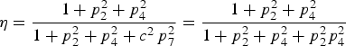 $$\eta = \displaystyle{{1 + p_2^2 + p_4^2} \over {1 + p_2^2 + p_4^2 + {c^2}\, p_7^2}} = \displaystyle{{1 + p_2^2 + p_4^2} \over {1 + p_2^2 + p_4^2 + p_2^2 p_4^2}} $$
Let c = 1, p 7 = −p 2p 4. The solution of Equations (32) when b = 0 is
 $$a = c = 1\comma b = d = 0\comma {\,p_7} = - {\,p_2}{\,p_4}\comma {\,p_5} = {\,p_6} = {\,p_8} = 0$$
When b ≠ 0, Equations (32) are rewritten as
 $$\left\{ \matrix{d = bc \hfill \cr c{p_2}{\,p_7} - {\,p_4} = 0\comma \hfill \cr {\,p_2}{\,p_4}\left( {1 - {b^2}} \right) + {\,p_7}\left( {c - bd} \right) = 0 \hfill} \right.$$
Solving Equations (35), we obtain b = 1, c = d, cp 7 = p 4/p 2. Substituting them into Equation (15), the combination efficiency when b ≠ 0 is
 $$\eta = \displaystyle{{\left( {{a^2} + {b^2}} \right)\left( {1 + p_2^2 + p_4^2} \right)} \over {\left( {{a^2} + {b^2}} \right)\left( {1 + p_2^2 + p_4^2} \right) + \left( {{c^2} + {d^2}} \right)p_7^2}} = \displaystyle{{\,p_2^2 \left( {1 + p_2^2 + p_4^2} \right)} \over {\,p_2^2 \left( {1 + p_2^2 + p_4^2} \right) + p_4^2}} $$
Let c = 1. The solution of Equations (32) when b ≠ 0 is
 $$a = b = c = d = 1\comma {\,p_7} = \displaystyle{{{\,p_4}} \over {{\,p_2}}}\comma{\,p_5} = {\,p_6} = {\,p_8} = 0$$
Comparing Equation (34) with Equation (36), we obtain the maximum combination efficiency of Case Three, which is expressed as
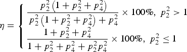 $$\eta = \left\{ \matrix{\displaystyle{{\,p_2^2 \left( {1 + p_2^2 + p_4^2} \right)} \over {\,p_2^2 \left( {1 + p_2^2 + p_4^2} \right) + p_4^2}} \times 100\%\comma\ p_2^2 \gt 1 \hfill \cr \displaystyle{{1 + p_2^2 + p_4^2} \over {1 + p_2^2 + p_4^2 + p_2^2 p_4^2}} \times 100\%\comma\ p_2^2 \le 1 \hfill} \right.$$
The corresponding theoretical optimal solution in this case is:
 $$\left\{ \matrix{a = b = c = d = 1\comma{\,p_7} = \displaystyle{{{\,p_4}} \over {{\,p_2}}}\comma{\,p_5} = {\,p_6} = {\,p_8} = 0\comma \;p_2^2 \gt 1 \hfill \cr a = c = 1\comma b = d = 0\comma{\,p_7} = - {\,p_2}{\,p_4}\comma{\,p_5} = {\,p_6} = {\,p_8} = 0\comma \;p_2^2 \gt 1 \hfill} \right.$$
 According to Equation (37), we calculate the combination efficiency versus  $p_4^2 $ for a given value of p 2, and show them in Figure 8. For a given value of p 2, with the decrease of
  $p_4^2 $, a higher combination efficiency is expected to be achieved. In particular, when
  $p_4^2 = 0$, it means that only two signal components s 1 and s 2 are modulated at the lower sideband. This is a QPSK modulation at the lower sideband, whose combination efficiency is 100%.
Figure 8. Combination efficiency vs. the power of s 4(t) for different p 2.
We also obtain the numerical optimal solution of Case Three by solving the optimisation problem Equation (16). We list several numerical optimal solutions for different  $p_2^2 $ and
  $p_4^2 $ in this case in Table 5. It can be easily verified that the combination efficiencies of these numerical optimal solutions are consistent with the theoretical results of Equation (37).
Table 5. Examples of numerical optimal solutions for Case Three.
Equation (38) shows that there are two kinds of subcarriers for Case Three. However, the analysis shows the PSD of these two kinds of subcarriers are identical. The PSD is shown in Figure 7. The LUT for Case Three can be generated following the method of Case Two, which we do not discuss in detail here.
3.4. General Case
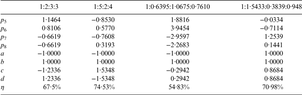
For an arbitrary PAR, Equation (14) is one solution of Equations (7). Substituting Equation (14) into Equation (13), we can then obtain the corresponding GAltBOC modulation. In other words, Equation (14) can ensure that our GAltBOC method is applicable for an arbitrary PAR. However, for the general case, it is difficult to derive the analytical expression of the optimal solution. Thus we obtain the numerical optimal solution by solving the optimisation problem Equation (16). Table 6 lists the numerical optimal solutions for several general cases as examples. The first two PAR schemes are integer ratios, but they are not special. The last two PAR schemes are be generated randomly. We can see that the combination efficiency of a general case is relatively low.
Table 6. Numerical optimal solutions for several general cases.
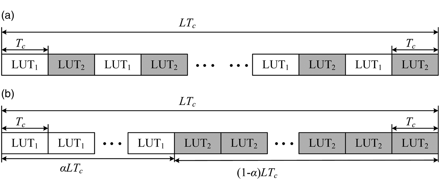
4. INTERLACING GAltBOC MODULATION
Case One and Case Two are two kinds of valuable cases. For Case One, the combination efficiency is higher than AltBOC when the power of lower sideband and upper sideband are unequal. Unfortunately, for some practical applications, it is desired that the power of upper sideband and lower sideband are the same (Yao and Lu, Reference Yao and Lu2013b). For Case Two, the required frequency of the driving clock is only half the frequency of AltBOC. However, its combination efficiency is lower than 80% when the power ratio of pilot and data components is smaller than four. In order to make full use of their advantages, and avoid their disadvantages, on the basis of GAltBOC modulation, we introduce the interlacing technique, and propose the Interlacing GAltBOC (IGAltBOC) modulation.
The IGAltBOC modulation signal is obtained by interlacing two GAltBOC modulation signals with different PAR schemes. Similar to GAltBOC modulation, the IGAltBOC modulation is denoted as IGAltBOC(m,n,r), where f s = m × 1·023 MHz is the subcarrier frequency of IGAltBOC, and R c = n × 1·023Mcps is the code rate. r is the power ratio of four signal components. For clarity, the IGAltBOC(m, n, r) modulation signal can be defined by
 $${\rm IGAltBOC}(m\comma n\comma r) = \alpha {\rm GAltBOC}(m\comma n\comma {r_1}) + \left( {1 - \alpha} \right){\rm GAltBOC}(m\comma n\comma {r_2})$$
Equation (39) means that the IGAltBOC(m,n,r) modulation is obtained by interlacing the first GAltBOC(m,n,r 1) modulation and the second GAltBOC(m, n, r 2) modulation. r 1 is the PAR of the first GAltBOC signal, and α is the occurrence probability of the first GAltBOC signal during a code period. r 2 is the PAR of the second GAltBOC signal, and 1 − α is the occurrence probability of the second GAltBOC signal during a code period.
The IGAltBOC modulation signal is generated by using the phase LUTs of two GAltBOC modulation signals. In order to simplify the generation of the IGAltBOC signal, we consider two kinds of structures, which are shown in Figure 9. LUT1 represents the LUT of the first GAltBOC modulation, and LUT2 represents the LUT of the second GAltBOC modulation. T c = 1/R c is the chip duration, and L is the code length.
Figure 9. The proposed structure of IGAltBOC modulation. (a) α = 0·5. (b) α ≠ 0·5.
When α = 0.5, the structure in Figure 9(a) is selected. We can see that the LUT1 is used in the first (even) slot, and LUT2 is used in the second (odd) slot. In fact, the interlacing structure of Figure 9(a) is the time-multiplexing structure adopted in TMOC-QPSK (Shivaramaiah and Dempster, Reference Shivaramaiah and Dempster2013). Accurately speaking, the time-multiplexing technique can be seen as a special interlacing technique. When α ≠ 0.5, Figure 9(b) is selected. The LUT1 is adopted form the 1st chip to the α · L th chips, and the LUT2 is adopted from the (α · L + 1) th chip to the Lth chips. Obviously, in order to generate the IGAltBOC signal, an additional gating signal is required to switch these two LUTs.
When r 1 and r 2 are given, the PAR, combination efficiency and PSD of IGAltBOC modulation are determined by the value of α. Let η 1 and η 2 represent the combination efficiencies of GAltBOC(m, n, r 1) modulation and GAltBOC(m, n, r 2) modulation respectively. G 1(f) and G 2(f) represent the PSD of GAltBOC(m, n, r 1) modulation and GAltBOC(m, n, r 2) modulation respectively. Then the combination efficiency of IGAltBOC(m, n, r) modulation is given by
 $$\eta = \alpha {\eta _1} + \left( {1 - \alpha} \right){\eta _2}$$
The PSD of IGAltBOC(m, n, r) modulation is given by
 $${G_{IGAltBOC}}\left( f \right) = \alpha {G_1}\left( f \right) + \left( {1 - \alpha} \right){G_2}\left( f \right)$$
Now we can achieve the IGAltBOC modulation with equal PAR scheme by exploiting the GAltBOC modulation of Case One, Case Two and Case Three. For example,
 $$\eqalign{& {\rm IGAltBOC}(m\comma\ n\comma\ 1:1:1:1)\; =\; \displaystyle{1 \over 2}{\rm GAltBOC}(n\comma\ m\comma\ 1:1:{\gamma ^2}:{\gamma ^2}) \,\cr &+\, \displaystyle{1 \over 2}{\rm GAltBOC}(15\comma\ 10\comma\ 1:{{1:1} / {{\gamma ^2}}}:{1 / {{\gamma ^2}}}) \cr & {\rm IGAltBOC}(m\comma\ n\comma\ 1:1:1:1) \;=\; \displaystyle{1 \over 2}{\rm GAltBOC}(m\comma\ n\comma\ 1:0:1:0) \cr &\;+\; \displaystyle{1 \over 2}{\rm GAltBOC}(m\comma\ n\comma\ 0:1:0:1) \cr & {\rm IGAltBOC}(m\comma\ n\comma\ 1:1:1:1) = \displaystyle{1 \over 2}{\rm GAltBOC}(m\comma\ n\comma\ 1:1:0:0) \cr &+ \displaystyle{1 \over 2}{\rm GAltBOC}(m\comma\ n\comma\ 0:0:1:1)} $$
The first IGAltBOC(m, n, 1:1:1:1) modulation in Equation (41) is obtained based on the GAltBOC modulation of Case One. It is the equal PAR scheme, and retains the high combination efficiency of the GAltBOC(m, n, 1:1:γ 2:γ 2) modulation. The second and third IGAltBOC(m, n, 1:1:1:1) modulation signals are based on the GAltBOC modulation of Cases Two and Three. In fact, we can further find that the second IGAltBOC(m, n, 1:1:1:1) modulation is the “TMOC-QPSK-ab” modulation, and the third IGAltBOC(m, n, 1:1:1:1) modulation is the “TMOC-QPSK-IQ” modulation (Shivaramaiah and Dempster, Reference Shivaramaiah and Dempster2013).
The IGAltBOC modulation signal with PAR 1:γ 2:1: γ 2 can also be achieved. For example,
 $$\eqalign{{\rm IGAltBOC}(m\comma\ n\comma\ 1:3:1:3) &= \displaystyle{5 \over 6}{\rm GAltBOC}(m\comma\ n\comma\ 1:7:1:7) \cr &\quad + \displaystyle{1 \over 6}{\rm GAltBOC}(m\comma\ n\comma\ 1:\displaystyle{1 \over 7}:1:\displaystyle{1 \over 7})}$$
The combination efficiency of the above IGAltBOC(m, n, 1:3:1:3) signal is 87·5%, which is much higher than 75%, where 75% is the combination efficiency of GAltBOC(m,n,1:3:1:3) modulation.
Furthermore, we can obtain some general PAR schemes by exploiting Cases One, Two and Three. For example, to achieve the PAR 1:2:3:3, we can set α = 0.5, r 1 = 1:1:3:3, r 2 = 1:3:1:3, and then the combination efficiency of IGAltBOC(m, n, 1:2:3:3) is 81·48%, which is much higher than 67·5%.
To sum up, compared with GAltBOC modulation, the IGAltBOC modulation can further improve the combination efficiency while keeping PAR unchanged.
5. SIMULATION RESULTS AND PERFORMANCE VALIDATION
In this section, the PSD, PAR and correlator functions of the proposed GAltBOC and IGAltBOC signals are validated by simulation. These parameters of Galileo E5 signal are used: Code rate is taken as 10·23Mcps, subcarrier frequency is 15*1·023 MHz, and the length of PRN codes is 10230 (Galileo OS SIS ICD, 2010). The equal power allocation 1:1:1:1 and the unequal power allocation 1:1:3:3 and 1:3:1:3 are considered. GAltBOC(15, 10, 1:1:3:3), GAltBOC(15, 10, 1:3:1:3), IGAltBOC(15, 10, 1:3:1:3) and IGAltBOC(15, 10, 1:1:1:1) signals are analysed. The IGAltBOC(15, 10, 1:3:1:3) defined in Equation (42) is adopted, so the corresponding IGAltBOC(15, 10, 1:1:1:1) signal is chosen as
 $$\eqalign{{\rm IGAltBOC}(15\comma10\comma1:1:1:1) &= \displaystyle{1 \over 2}{\rm GAltBOC}(15\comma10\comma1:1:7:7) \cr &\quad+ \displaystyle{1 \over 2}{\rm GAltBOC}(15\comma10\comma1:{{1:1} / 7}:{1 / 7})}$$
5.1. Power Spectrum Density
The PSD of the proposed signals were simulated by generating the signals with PRN codes at the complex sampling rate of 300*1·023 MHz and averaging the results of periodogram algorithm through 1000 Monte Carlo runs (Dafesh and Cahn, Reference Dafesh and Cahn2009). Then the spectrum measurement was corrected by a function of frequency to compensate for the sampling effect (Zhang et al., Reference Zhang, Zhou and Wang2011). The PSD of simulation and theory are shown in Figure 10. The theoretical PSD are obtained by Equations (17) and (40).
Figure 10. The simulation and theory PSD. (a) IGAltBOC(15, 10, 1:1:1:1) and GAltBOC(15, 10, 1:1:3:3) (b) GAltBOC(15, 10, 1:3:1:3) and IGAltBOC(15, 10, 1:3:1:3).
Figure 10 clearly shows that the simulation curves are consistent with the theory curve. For the GAltBOC(15,10,1:1:3:3) modulation, the upper main-lobe of its PSD is 4·77 dB higher than that of the lower sideband. This is because the designed power of upper sideband is 4·77 dB more than that of lower sideband. For the other three signals, because the lower sideband and upper sideband have equal power, the two main-lobes of PSD are the same.
5.2. Power Allocation Ratio
As we know, the ratio of the received power of each signal component cannot strictly meet the designed PAR in the case of bandwidth-limitation. To analyse the ratio of the received power, we need to measure the received power of each signal component. The received power can be measured by the average output of correlator (Dafesh and Cahn, Reference Dafesh and Cahn2009). Thus, we first obtain the correlation function by simulation. Figure 11 shows the simulation architecture. s 1, s 2, s 3 and s 4 are the four PRN code signals. s(t) represents the baseband signal of GAltBOC modulation or IGAltBOC modulation, which is generated by the LUT method.
Figure 11. The simulation architecture to generate the correlator output.
Similar to TMOC-QPSK, the proposed modulation signals can be received by wideband processing or independent sideband processing (Shivaramaiah and Dempster, Reference Shivaramaiah and Dempster2013). The correlation function of the wideband processing R s(τ) is generated by correlating  $\hat s\left( t \right)$ with s*(t − τ), where
  $\hat s\left( t \right)$ is the band limited signal of s(t), and s(t − τ) is the local reference signal of s(t) with delay τ. To generate the cross correlation function of the sideband processing, one sideband in frequency domain of s(t) is firstly shifted to the zero frequency. For s 1 and s 2, s(t) is multiplied with e j2πf st. For s 3 and s 4, s(t) is multiplied with e −j2πf st. After Sideband (SB) filtering, the result is correlated with the corresponding local reference signals s 1(t − τ), s 2(t − τ), s 3(t − τ) or s 4(t − τ).
  ${R_{{s_1}}}\!\left( \tau \right)$,
  ${R_{{s_2}}}\!\left( \tau \right)$,
  ${R_{{s_3}}}\left( \tau \right)$ and
  ${R_{{s_4}}}\left( \tau \right)$ are the cross correlation functions of s 1, s 2, s 3 and s 4 respectively. Note that the power of s(t) has been normalised, and the power of these local reference signals is also normalised.
The filters are the ideal brick-wall filters with transfer function H(f),
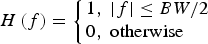 $$H\left( f \right) = \left\{ \matrix{1\comma\;\left \vert f \right \vert \le BW/2 \hfill \cr 0\comma\;{\rm otherwise} \hfill} \right.$$
where BW is the bandwidth of the filter. For the wideband processing, BW is 51·15 MHz. For the independent sideband processing, BW is 20·46 MHz (Galileo OS SIS ICD, 2010).
Figure 12 shows the correlation functions of AltBOC(15,10), GAltBOC(15, 10, 1:1:3:3) and IGAltBOC(15, 10, 1:1:1:1). Figure 13 shows the correlation functions of GAltBOC(15, 10, 1:3:1:3) and IGAltBOC(15, 10, 1:3:1:3). Figure 12(a) and Figure 13(a) are the cases of wideband processing, and Figure 12(b) and Figure 13(b) are the cases of single sideband processing. We can see that the correlation functions of the proposed GAltBOC and IGAltBOC are similar to AltBOC's. It is noted that the correlation peak of IGAltBOC(15, 10, 1:1:1:1) is higher than AltBOC's correlation peak, which demonstrates that the proposed IGAltBOC(15, 10, 1:1:1:1) signal has more useful power compared to AltBOC.
Figure 12. Correlation functions of IGAltBOC(15, 10, 1:1:1:1), GAltBOC(15, 10, 1:1:3:3) and AltBOC(15, 10). (a) Wideband processing (b) Single sideband processing.
Figure 13. Correlation functions of GAltBOC(15,10,1:3:1:3) and IGAltBOC(1:3:1:3). (a) Wideband processing (b) Single sideband processing.
|R s (0)|2 is the correlator output power of wideband processing, and  ${\left\vert {{R_{{s_1}}}\left( 0 \right)} \right\vert^2}$,
  ${\left\vert {{R_{{s_2}}}\left( 0 \right)} \right\vert^2}$,
  ${\left\vert {{R_{{s_3}}}\left( 0 \right)} \right\vert^2}$ and
  ${\left\vert {{R_{{s_4}}}\left( 0 \right)} \right\vert^2}$ correspond to the measured correlator output power of the four signal components (Yao and Lu, Reference Yao and Lu2013a). Because the power of s(t) is 1, the power of each signal component is much smaller than 1 and the correlation peaks of single signal components are lower than 1. For GAltBOC(15, 10, 1:3:1:3) and IGAltBOC(1:3:1:3), the power of the pilot component is three times the power of the data component. Therefore the correlation peaks of s 2 and s 4 are higher than the correlation parks of s 1 and s 3.
The values of correlation peaks are listed in Table 7. As a comparison, the results of AltBOC, TD-AltBOC and ACED are also analysed. In Table 7,  ${\left\vert {{R_{{s_1}}}\left( 0 \right)} \right\vert^2}:{\left\vert {{R_{{s_2}}}\left( 0 \right)} \right\vert^2}:{\left\vert {{R_{{s_3}}}\left( 0 \right)} \right\vert^2}:{\left\vert {{R_{{s_4}}}\left( 0 \right)} \right\vert^2}$ is the ratio of the received power, which is not strictly equal to the designed PAR. For a given PAR, we use the root mean square of the relative power error to characterise the bias error of PAR, which is defined as
 $$\Delta P = \sqrt {\sum\limits_{M = 1}^3 {\sum\limits_{N = M + 1}^4 {{{\left( {\displaystyle{{{{\left \vert {{R_{{s_N}}}\left( 0 \right)} \right \vert} ^2}} \over {{{\left \vert {{R_{{s_M}}}\left( 0 \right)} \right \vert} ^2}}} - \displaystyle{{{P_{{s_N}}}} \over {{P_{{s_M}}}}}} \right)}^2}}}} $$
where  $\left( {{{{{\left\vert {{R_{{s_N}}}\left( 0 \right)} \right\vert}^2}} / {{{\left\vert {{R_{{s_M}}}\left( 0 \right)} \right\vert}^2}}} - {{{P_{{s_N}}}} / {{P_{{s_M}}}}}} \right)$ is the relative power error between signal s N and signal s M (Zhang et al., Reference Zhang, Zhou and Wang2011).
  ${P_{{s_N}}}$ and
  ${P_{{s_M}}}$ are the designed power of signal s N and signal s M respectively. ΔP is used to denote the effect of filter on the PAR.
Table 7. The measured correlator output power in the case of 51·15 MHz bandwidth-limitation.
In the case of equal power allocation, compared with AltBOC and TD-AltBOC, our IGAltBOC(15, 10, 1:1:1:1) signal can receive the most useful power, and the bias error of PAR is neglected. More useful power usually means better tracking accuracy. Comparing GAltBOC(15, 10, 1:1:3:3) with ACED(15, 10, 1:1:3:3), we can make the same conclusion. For a PAR of 1:3:1:3, our GAltBOC and IGAltBOC signals have more received power for the wideband processing, but less received power for single sideband processing. The received power of IGAltBOC signal is higher than GAltBOC for single sideband processing, this is because IGAltBOC(15, 10, 1:3:1:3) modulation has a higher combination efficiency than GAltBOC(15, 10, 1:3:1:3) modulation. Note that the filter has more severe impact on ACED modulation than the proposed signals.
As previously mentioned, the combination efficiency represents the proportion of the useful power in the total transmitting power. Here, we can also verify the combination efficiency by measuring the correlator output power. The useful signal power in the main lobes can be expressed as (Huang et al., Reference Huang, Zhu, Tang, Gong and Ou2015)
 $${P_{main}} = {A^2} \cdot \eta \cdot {\eta _{{\,f_s}}}$$
where A 2 denotes total transmitting power, and is set to 1 in simulations. η is the combination efficiency.  ${\eta _{{f_s}}}$ represents the fraction of fundamental harmonic in square wave complex sub-carrier, which is 94·96% for Case One and 81·06% for Case Two in the proposed signals. P main is measured as the sum of the correlator output power in the case of infinite bandwidth. The results are listed in Table 8. We can see that the simulated and theoretical values agree well, supporting the analysis of combination efficiency in Section 3. Since
  ${\eta _{{f_s}}}$ depends on the PAR, when the PAR is given, higher combination efficiency also indicates the more useful power in main lobes.
Table 8. The measured correlator output power in the case of infinite bandwidth.
5.3. Code tracking error
In this section, we calculate the code tracking error for wideband processing in different carrier-to-noise-density ratio (C/N 0). The expression of code tracking error standard deviation has been provided by Sleewaegen and Wilde (Reference Sleewaegen and Wilde2004). The received bandwidth is 50·15 MHz, correlator spacing is 0·1 chips, the coherent integration time is 1 ms, and the code loop noise bandwidth is 1 Hz (Tawk et al., Reference Tawk, Botteron, Jovanovic and Farine2012). The results are shown in Figure 14.
Figure 14. Code tracking error versus C/N 0. (a) PAR is 1:1:1:1. (b) PAR is 1:1:3:3. (c) PAR is 1:1:3:3.
Figure 14(a) shows the code tracking error curve (expressed in metres) versus C/N 0 of AltBOC(15,10), TD-AltBOC(15,10) and IGAltBOC(15,10,1:1:1:1). As expected, for the equal power allocation scheme, the code tracking performance of IGAltBOC signal is relatively better than AltBOC's and TD-AltBOC's due to the more useful power. Figure 14(b) shows the code tracking performance of ACED(15, 10, 1:1:3:3) and GAltBOC(15, 10, 1:1:3:3). It can be seen that the tracking accuracy of GAltBOC(15, 10, 1:1:3:3) signal is slightly better than ACED(15, 10, 1:3:1:3). Figure 14(c) shows the code tracking performance of ACED(15, 10, 1:3:1:3), GAltBOC(15, 10, 1:3:1:3) and IGAltBOC(15, 10, 1:3:1:3). It can be observed that these three modulation signals have almost the same code tracking performance. The above results demonstrate that the proposed modulation signals can maintain the same level or even slightly better code tracking accuracy compared with AltBOC and ACED when adjusting the power allocation ratio.
5.4. Implementation Complexities
All of the above signals can be generated by arithmetic computation method and phase LUT method. However, the LUT method is more suited for hardware implementations (Shivaramaiah and Dempster, Reference Shivaramaiah and Dempster2013). Thus, we only discuss the implementation complexities of the LUT method.
We first show the constellation diagrams of GAltBOC(15, 10, 1:1:3:3), GAltBOC(15, 10, 1:3:1:3), IGAltBOC(15, 10, 1:1:1:1) and IGAltBOC(15, 10, 1:3:1:3) signals in Figure 15. The constellation diagrams can be obtained from Tables 2 and 4. We can see that the proposed methods use sophisticated phase values to reach the designed PAR. Especially, the GAltBOC(15, 10, 1:1:3:3) and IGAltBOC(15, 10, 1:1:1:1) have 32 different phase values in the modulation constellations. This means the implementation of signal generation and correlator would involve floating point arithmetic, which is expensive in terms of computation for a practical receiver.
Figure 15. The constellation diagram (a) GAltBOC(15, 10, 1:1:3:3) (b) GAltBOC(15, 10, 1:3:1:3) (c) IGAltBOC(15, 10, 1:1:1:1) (d) IGAltBOC(15, 10, 1:3:1:3).
To reduce the complexity, we can use the scaled integer to approximate these values. As an example, the LUT method of GAltBOC(15,10,1:1:3:3) reference signal generation is shown in Figure 16. The three bits of the subcarrier NCO (which represent the eight phases of the subcarrier) and the four codes act as address inputs to the LUT. The accurate output values of the LUT should be {±0.063, ±0.3455, ±0.4193, ±0.6611, ±0.7503, ±0.9079, ±0.9384, ±0.9980}. These values are approximately represented as {±4, ±22, ±27, ±42, ±48, ±58, ±60, ±64}, which require 8 bits. The scaled integer approximation error is less than 1%. As a result, the LUT method requires two 128 × 8 LUTs, one for I and one for Q. Since the code mixer of correlator can also be implemented as an LUT (Shivaramaiah and Dempster, Reference Shivaramaiah and Dempster2010), the local reference signal s(t − τ) is an input to the code mixer and does not require true value representation. Thus we can use the mapped representation of s(t − τ). For GAltBOC(15, 10, 1:1:3:3), there are only 16 levels. 4 bits are sufficient to represent s(t − τ). Then the LUT method to generate GAltBOC(15, 10, 1:1:3:3) signal only requires two 128 × 4 LUTs.
Figure 16. LUT method of GAltBOC(15, 10, 1:1:3:3) reference signal generation.
According to the criterion for the best possible representation (Shivaramaiah and Dempster, Reference Shivaramaiah and Dempster2013), we list the arithmetic representation and mapped representation of local reference signal generation for different modulation signals in Table 9. The scaled integer approximation error is less than 1%.
Table 9. Arithmetic representation and mapped representation of local reference signal generation.
Figure 17 takes the LUT method of code mixer implementation in GAltBOC(15, 10, 1:1:3:3) modulation as an example. x(t) represents the received signal after carrier wiping-off, namely the carrier mixer output. For different modulation signals, the values of x(t) will only have eight levels {± 1, ±2, ±3, ±6}, a 3 bit encoding is sufficient (Shivaramaiah and Dempster, Reference Shivaramaiah and Dempster2010). The 7 bits of x(t) and  $\hat s\left( {t - \tau} \right)$ act as address inputs to the code mixer. Both of x(t) and
  $\hat s\left( {t - \tau} \right)$ are complex numbers, namely,
  $x\left( t \right) = {x_I}\left( t \right) + j{x_Q}\left( t \right), \hat s\left( {t - \tau} \right) = {\hat s_I}\left( {t - \tau} \right) + j{\hat s_Q}\left( {t - \tau} \right)$. The product of x(t) and
  ${\hat s}\left( {t - \tau} \right)$ is expressed as
 $$x\left( t \right) \cdot {{\hat s}^{\ast}} \left( {t - \tau} \right) = \left( {{x_I}\left( t \right) \cdot {{\hat s}_I}\left( {t - \tau} \right) + {x_Q}\left( t \right) \cdot {{\hat s}_Q}\left( {t - \tau} \right)} \right) + j\left( {{x_Q}\left( t \right) \cdot {{\hat s}_I}\left( {t - \tau} \right) - {x_I}\left( t \right) \cdot {{\hat s}_Q}\left( {t - \tau} \right)} \right)$$
Therefore, the maximum value of y(t) is ± 6 × 8 × 2 = ± 768, where y(t) is the output of code mixer. y(t) requires 11 bits. The LUT method of code mixer implementation in GAltBOC(15,10,1:1:3:3) requires four 128 × 11 tables and two adder/subtractors.
Figure 17. LUT method of code mixer implementation in GAltBOC(15, 10, 1:1:3:3).
Table 10 summarises the complexity comparison to realise the reference signal generator and the code mixer in different modulation signals. The required driving clock rate is also given. Note the size of LUT in IGAltBOC modulation is twice that of the size of LUT in corresponding GAltBOC modulation. This is because IGAltBOC modulation needs an additional bit for the gating signal. We can see that the complexities of the proposed signals are changing with the PAR.
Table 10. Complexity comparison.
For the equal power allocation scheme, Table 10 shows that the required clock rate in IGAltBOC(15, 10, 1:1:1:1) is the same as that in AltBOC(15,10). The implementation of reference signal generator and code mixer in IGAltBOC(15,10,1:1:1:1) is more complex than that in AltBOC(15,10) and TD-AltBOC(15,10). However, it should be noted that the PAR of the proposed signals is adjustable, and AltBOC modulation is a special case of GAltBOC modulation. Moreover, IGAltBOC modulation provides an additional modulation signal with equal PAR and higher combination efficiency at the expense of higher implementation complexity.
For PAR 1:3:1:3, compared with ACED, GAltBOC and IGAltBOC have a significant lower complexity of reference signal generator, and the same complexity of code mixer. For the PAR 1:1:3:3, we can see that the required clock rate of GAltBOC(15, 10, 1:1:3:3) is only one third of that in ACED(15, 10, 1:1:3:3), which results in an obviously lower implementation complexity of signal generation and smaller size LUT. This is very important to the signal generation at the satellite payload transmitter. Though the implementation of code mixer in GAltBOC(15, 10, 1:1:3:3) modulation is more complex than that in ACED(15, 10, 1:1:3:3) modulation, the implementation complexity of the reference signal generator in GAltBOC is only one third of that in ACED. As we know, the implementation complexity of code mixer can be reduced by reducing the accuracy of arithmetic representation in Table 9. Nevertheless, the complexity of signal generation cannot be reduced for a given signal. If the complexity of signal generation is too high, it would be too difficult or even impossible to generate the ideal signal for the satellite payload. Overall, compared with ACED, the main advantage of the proposed signals is to simplify the signal generation in the payload transmitter.
6. CONCLUSIONS
In this paper, a dual-sideband constant envelope modulation technique GAltBOC and its variant IGAltBOC are proposed. The proposed GAltBOC modulation can be seen as an extension of AltBOC modulation, in which the power ratio of four signal components can be adjusted according to different requirements. Three representative cases of GAltBOC modulation are discussed in detail, and the corresponding analytical expressions are derived. IGAltBOC modulation is generated by interlacing two GAltBOC signals with different PARs, which is used to further improve the combination efficiency for a given power ratio. The PSD, correlation functions, code tracking error and implementation complexities of the proposed methods are analysed by theory and simulation. Based on the results, we summarise the following conclusions:
The proposed GAltBOC modulation and IGAltBOC modulation indeed enhance the flexibility of PAR. Even in the case of bandwidth-limitation, the ratio of the received power is almost consistent with the designed PAR. It is emphasised that AltBOC modulation is a special case of GAltBOC modulation; TMOC-QPSK modulation can be seen as a special case of IGAltBOC modulation.
When the PAR is given, the IGAltBOC modulation can further improve the combination efficiency compared with GAltBOC modulation. Especially, the proposed IGAltBOC(15, 10, 1:1:1:1) signal has the higher combination efficiency and better code tracking performance than that in AltBOC(15,10) modulation at the expense of higher implementation complexity.
For the unequal power allocation scheme 1:3:1:3, compared with ACED(15, 10, 1:3:1:3) modulation, the proposed GAltBOC(15,10,1:3:1:3) and IGAltBOC(15, 10, 1:3:1:3) signals provide the same level code tracking accuracy for wideband processing with significantly lower implementation complexity.
For PAR 1:1:3:3, the proposed GAltBOC(15, 10, 1:1:3:3) modulation can receive more useful power and provide slightly better code tracking performance compared with ACED(15, 10, 1:1:3:3) modulation. The driving clock rate of GAltBOC(15, 10, 1:1:3:3) modulation is only a third of that of ACED(15, 10, 1:1:3:3) modulation, which results in an obviously lower implementation complexity of signal generation.
Given all that, the proposed modulation signals have significant advantages. Not only the power allocation ratio of the proposed signals can be adjusted to meet different requirements, but also the proposed signals can be easily generated in the satellite payload transmitter.
ACKNOWLEDGEMENTS
This work is supported by the National Natural Science Foundation of China (NSFC), Grant 61401171.