


Introduction
Three-dimensional (3D) imaging has found broad application in scanning electron microscopy (SEM) for decades [Reference Goldstein1–Reference Sturm5]. While stereophotography enhances the viewer’s attraction to an object, 3D images of small objects are of scientific value in several respects: (1) surface structures of objects can be submitted to a more detailed morphometric evaluation, (2) spatial arrangement of structures can be more efficiently elucidated, and (3) measurements of objects in all three dimensions can be made under certain conditions [Reference Goldstein1, Reference Sturm6-Reference Sturm7]. In many cases, measurements in the third dimension are not necessary, but images exhibiting a stereo-effect can be valuable in any case.
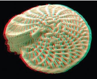
The ability to produce a large depth of field along the optic axis, typically 100 times larger than possible by light microscopy, has been a major attribute of the SEM since its inception. Using this depth of field in the SEM, a sub-millimeter object can be imaged in stereo by taking a pair of images, where the specimen was tilted by about 7 degrees between them. Figure 1 shows this procedure and a resulting image pair coded as a red-cyan anaglyph [Reference Sturm6–Reference Sturm8]. When viewed with red-cyan glasses, stunning stereo effects can be achieved by this conventional stereo imaging method.
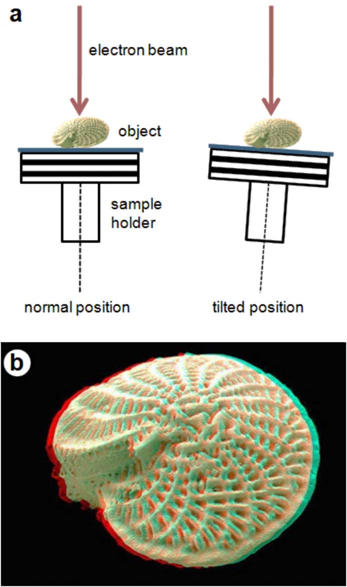
Figure 1 Sample tilting technique for the generation of stereo-images and its application to electron microscopy. (a) Basic principle, (b) result (anaglyph of a foraminifera, basic photo from UCL MIRACLE).
Recently, computer algorithms have been developed that allow the generation of stereo-images on the basis of a single SEM micrograph [Reference Raap and and Cypionka9]. This method, founded on the principle of object-depth mapping, has opened new possibilities because even previously recorded electron micrographs can be subjected to a re-evaluation by viewing them in stereo.
This article describes 3D imaging based on a single SEM photograph. Besides an explanation of the steps behind this computer-aided technique, the article introduces the reader to a freely available software implementation of the method (Picolay) [Reference Raap and and Cypionka9]. In addition, examples of stereo-images from different scientific disciplines (biology, paleontology, mineralogy) are provided.
Materials and Methods
Stereo from a single micrograph
Object-depth mapping, the foundation of one-photograph stereo-imaging, is based on a rather simple principle. It is commonly assumed that parts of an object nearer to the viewer are brighter in appearance, whereas parts of the object at greater distance from the viewer are darker [Reference Raap and and Cypionka9]. Different levels of brightness and darkness are attributed to respective color codes, finally resulting in a color map of the object (Figure 2). From each color code an individual image is reconstructed so that an image stack is produced at the end. This stack is used for the generation of the 3D image according to a well-defined procedure [Reference Sturm10]. In general, two semi-images characterized by different focus planes show a stereoscopic deviation, where object points of the left image do not have exactly the same positions as corresponding object points of the right image. As a consequence of this phenomenon, simultaneous viewing of both images as a stereo-pair produces a spatial effect due to the image fusion capability of the brain [Reference Sturm7–Reference Sturm10]. Concretely speaking, the brain cannot distinguish between viewing two images with different perspective of the object and watching the object itself.

Figure 2 Concept of object-depth mapping and related 3D imaging offered by the computer program Picolay [Reference Sturm9]. (a) Working space window with the raw image (conodont species Apsidognathus tuberculatus) and menu bar, (b) computed depth map of the microscopic object, (c) resulting red-cyan anaglyph (basic photo from UCL MIRACLE).
Step-by-step procedure
The first task is to obtain an SEM image of the object where all heights in the object are in focus. To obtain the desired large depth of field, switch to a small objective aperture and lower the specimen in the stage to create a long working distance between the specimen and the final lens [Reference Goldstein1]. Object-depth mapping can be realized with professional commercial software such as Adobe PhotoshopTM, but it also can be accomplished with free computer programs like Picolay (http://www.picolay.de), developed by Heribert Cypionka [Reference Raap and and Cypionka9]. After import of an SEM image into the working space of the program, the user must execute two main steps: (1) import of the micrograph to the results window, and (2) generation of the object-depth map. Both procedures can be easily carried out using the EDIT context menu in the menu bar of Picolay (Figure 2a). Production of the object-depth map enables use of the 3D context menu (Figure 2b), where different setups and types of stereo-images can be selected. Besides classical stereopairs, the user can also generate red-cyan anaglyphs and animated GIFs (“rocking GIFs”) that make special stereo viewing devices unnecessary. Intensity of the stereo effect can be varied by changing the computed rotation angle of the item or the extent of the spatial dimension in the z-direction.
Production of a specimen tilt-based stereo-pair with the help of an object-depth map has to be imagined as follows: Based on the depth map and its included 3D information, the program is enabled to model edges and faces of the object that are not fully visible on the electron-micrograph. For this process a specific image rendering procedure is used, where respective object structures are extrapolated by using related mathematical algorithms. Computer-aided reconstruction of partly visible object components finally allows the rotation of the object by a small angle (1 to 10°). Any increase of this rotation angle commonly results in a reduction of the model accuracy, so that angles below 5° provide the best results [Reference Raap and and Cypionka9].
Three-dimensional images created with Picolay are automatically saved in the folder containing the raw images. Animated GIFs are primarily thought of for presentations in the World Wide Web, but they also can be used for PowerpointTM slide shows and similar applications.
Results
As described above, images from the SEM exhibiting large depth of field can be processed into stereo-pair anaglyphs. Figures 3 through 5 show some examples of 3D anaglyph images, which should be viewed with red-cyan glasses. Jumping spiders are several millimeters in size, and they are attractive objects for SEM examination. With the help of a 3D front view, the eyes and extremities as well as the arrangement of the sensory hairs can be studied in detail (Figure 3, top). By increasing the image magnification, the morphology of the sensory hairs and other sensory organs (for example, lyriform organs) of tarantulas and other spiders may be observed, thereby providing a better understanding of their structural functionality (Figure 3, bottom).

Figure 3 Red-cyan anaglyphs of single-electron micrographs reconstructed by object-depth mapping. (Top) Front view of a jumping spider (Salticus sp.) with typical position of the eyes and arrangement of the claws. Image width = 4.5 mm. (Bottom) detailed view on the sensory hairs and lyriform organs of a tarantula. Image width = 250 µm. (Original image: https://vogelspinnenforum.ch/index.php/Thread/9436-Bilder-ganz-nah-REM.)

Figure 4 Globular shell of a radiolarian (diameter = 125 µm). An example of red-cyan anaglyphs of microfossils photographed with the SEM.

Figure 5 Zircon crystal with slightly moderated faces (length = 150 µm). An example of 3D imaging in mineralogy.
In the field of paleontology, unicellular organisms that leave skeletal remains rank among the most interesting study objects. Figure 4 shows a radiolarian (genus Actinomma) measuring between 100 and 150 µm in size. Three-dimensional images give an impression of the shell depth.
Morphological studies of sub-millimeter-sized crystals represent another area where the SEM excels. Figure 5 shows the single crystal facets of a zircon crystal. In the case of such small polyhedral objects, modeled viewing angles between the two semi-images should be on the order of 3 to 5°.
Conclusion
Over many decades 3D photography has become a standard technique for the detailed documentation of macroscopic and microscopic objects. Whereas most stereo documentation has been accomplished by taking two images at different angles to the object, 3D imaging has been achieved recently from single images with the help of appropriate computer software. Thus, even SEM micrographs with large depth of field produced in the 1970s or 1980s can be converted into 3D images.


