


1. Introduction
There is considerable interest in the design of microfluidic systems to enrich very dilute suspensions of particles such as cancer cells or high value-added drugs or reagents (Hur et al. Reference Hur, Henderson-Maclennan, McCabe and Di Carlo2011; Kok, Segers & Versluis Reference Kok, Segers and Versluis2015; Warkiani et al. Reference Warkiani, Tay, Khoo, Xiaofeng, Han and Lim2015; Nivedita et al. Reference Nivedita, Garg, Lee and Papautsky2017; Wang et al. Reference Wang, Li, Zhang, Ban, Chen, Du, Feng and Liu2017). One class of devices relies on the use of a bifurcating channel where the particles are sent into one specific branch by means of hydrodynamic forces. Correspondingly, a number of numerical models have focused on the path selection of a capsule (a liquid drop enclosed by an impermeable deformable membrane) suspended in an external fluid flowing through a straight microchannel with a side branch (Barber et al. Reference Barber, Alberding, Restrepo and Secomb2008; Woolfenden & Blyth Reference Woolfenden and Blyth2011; Wang et al. Reference Wang, Sui, Salsac, Barthès-Biesel and Wang2016; Villone et al. Reference Villone, Trofa, Hulsen and Maffettone2017; Wang et al. Reference Wang, Sui, Salsac, Barthès-Biesel and Wang2018). Considering a capsule allows us to model a wide variety of particles from cells to encapsulated drugs. The path selection of a single capsule has been found to be dependent on the flow rate split between the two branches, capsule deformation (Villone et al. Reference Villone, Trofa, Hulsen and Maffettone2017), capsule position in the feeding channel (Barber et al. Reference Barber, Alberding, Restrepo and Secomb2008), flow inertia (Wang et al. Reference Wang, Sui, Salsac, Barthès-Biesel and Wang2016) and bifurcation geometry (Wang et al. Reference Wang, Sui, Salsac, Barthès-Biesel and Wang2018). This indicates that such a bifurcated channel is promising as a microfluidic tool for suspension enrichment or for sorting deformable capsules/cells. However, the above studies mostly considered a single capsule: this corresponds to a very dilute system where capsules are so far apart in the bifurcation that the hydrodynamic interaction between them is too weak to affect their individual trajectory. The question which arises in practice is how dilute the suspension should be for the interactions between capsules to be negligible and the separation system to be fully under control.
Relevant to hydrodynamic interaction between capsules, extensive research has concerned the flow of dense red blood cell suspensions at a bifurcation (Pries et al. Reference Pries, Secomb, Gaehtgens and Gross1990; Hyakutake & Nagai Reference Hyakutake and Nagai2015; Shen et al. Reference Shen, Coupier, Kaoui, Polack, Harting, Misbah and Podgorski2016; Balogh & Bagchi Reference Balogh and Bagchi2017; Ye & Peng Reference Ye and Peng2019), as a model for blood flows in the microcirculation. The primary focus of these studies was on the overall cell partitioning at the bifurcation. In dense suspensions, hydrodynamic interactions between multiple cells are strong, complicated and difficult to control. Therefore, a dense suspension may not be an ideal situation for sorting or enrichment using the aforementioned microfluidic geometry.
Studies of the hydrodynamic interaction between capsules in a branched microchannel in a dilute suspension are very limited. Barber, Restrepo & Secomb (Reference Barber, Restrepo and Secomb2011) pioneered the research of two-dimensional (2-D) capsules at a symmetric  $Y$-shaped bifurcation. It was found that the existence of a capsule in a downstream branch could block the entrance of the following one into the same branch, when the distance between capsules is sufficiently small. However, the work was limited to a pair of capsules in 2-D flows, which is a strong limitation because capsules are three-dimensional objects.
The present study aims to systematically consider, for the first time, the hydrodynamic interaction and path selection of a train of three-dimensional (3-D) initially spherical capsules flowing in a microfluidic asymmetric bifurcation consisting of a straight square channel with an orthogonal side branch of the same cross-section. The capsules are identical, initially equally spaced, and their size is comparable to the cross-sectional dimension of the channel. They are enclosed by a strain-hardening membrane and the internal fluid has the same viscosity as the external fluid. The capsules are centred along the feeding channel axis by hydrodynamic forces or by some flow-focusing devices. The objectives of the present study are two-fold: first, to uncover the influence of the initial interspacing between capsules in the feeding channel on the path selection phase diagram of capsules at the channel bifurcation region; second, to establish the threshold in initial interspacing above which hydrodynamic interactions become too weak to affect the capsule path selection (i.e. a capsule destination is identical to that of a single non-interacting capsule).
The paper is organised as follows: the flow geometry of the branched channel, the governing equations and the main parameters are presented in § 2; the numerical method and validations are presented in § 3. To facilitate the understanding of the results of a capsule train, we first consider the path selection of two capsules at the channel bifurcation in § 4. The results of a capsule train are then presented in § 5, where we focus on the path selection phase diagram and the critical initial interspacing  $d_{ct}$ above which capsule interactions have negligible effects on capsule path selection. In § 6, we discuss the relationship between a capsule train and a two-capsule system, and the implications of the present results to practical capsule enrichment experiments. Finally we summarise our findings in § 7.
2. Problem statement
We consider a train of equally spaced liquid-core capsules flowing through a straight channel with an orthogonal side branch. The channel geometry is shown in figure 1. Both the straight channel and the side branch have the same square cross-section with a side length of  $2l$. The length of the upstream parent channel is $20l$ and the length of both daughter channels is $10l$. The side branch and the straight channel are centre-connected, their joining corners are rounded, as is usually the case in microchannels fabricated using soft lithography. We choose a curvature radius of $0.4l$ and study the influence of this value in the numerical validation in § 3. A 3-D Cartesian coordinate system is defined with the $x$-axis along the axis of the straight channel, $z$-axis along the side branch axis and $x=y=z=0$ at the bifurcation centre.

Figure 1. Geometry of the branched channel used in the 3-D simulation. The shadow represents the bifurcation region. Top left inset shows the geometry in three dimensions.
All the capsules are initially spherical with radius  $a$. Each capsule is enclosed by a hyperelastic membrane with a small bending stiffness. The fluids inside and outside the capsule are incompressible Newtonian liquids with identical viscosity $\mu$ and density $\rho$. Capsules are regularly released on the centreline of the parent channel within the cross-section $S_c$, which is at a distance $2l$ from the entrance $S_0$ (figure 1). The release of a new capsule occurs when the mass centre of the capsule ahead arrives at the plane $S_{c}'$ which is at a distance $d$ downstream from $S_c$. Such an approach allows us to consider a train of capsules with an initial interspacing $d$ without using a very long parent channel. We identify quantities related to the $i{\text {th}}$ capsule with the index $i$.
$i$.
The fluid motion in the channel is governed by the Navier–Stokes equations. A no-slip boundary condition is imposed at the channel wall. Fully developed laminar channel flow profiles are set at the inlet  $S_0$ and the two outlets $S_1$ and $S_2$ with flow rates $Q_0$, $Q_1$ and $Q_2$, such that $Q_0=Q_1+Q_2$. The velocity profile at the inlet square cross-section $S_0$ is (Pozrikidis Reference Pozrikidis1997; Hu, Salsac & Barthès-Biesel Reference Hu, Salsac and Barthès-Biesel2012)
 \begin{equation} u(y, z)=\frac{{\rm \pi} V \sum\left[\dfrac{1}{n^{3}}-\dfrac{\cosh n {\rm \pi}y / 2l}{n^{3} \cosh n {\rm \pi}/ 2}\right] \sin n {\rm \pi}(z / 2l+1 / 2)}{2\left[\dfrac{{\rm \pi}^{4}}{96}-\sum \dfrac{\tanh n {\rm \pi}/ 2}{n^{5} {\rm \pi}/ 2}\right]} \quad n=1,3, \ldots, \end{equation}
where  $V$ is the mean flow velocity. The present flow-rate-control set-up models microfluidic applications where flow is controlled by multiple syringe pumps. The fluid also has a no-slip boundary condition at both sides of the membrane of each capsule. The load $\boldsymbol {q}$ on the membrane, which arises from the viscous traction jump, is balanced by the in-plane elastic tension tensor $\boldsymbol {T}$ and bending force $\boldsymbol {f}_{\boldsymbol {b}}$. Thus the membrane equilibrium equation is
 \begin{equation} \boldsymbol{q}+\boldsymbol{\nabla}_s \boldsymbol{\cdot} \boldsymbol{T}+\boldsymbol{f}_b=\boldsymbol{0}, \end{equation}
where  $\boldsymbol {\nabla }_{s}=(\boldsymbol {I}-\boldsymbol {n}\boldsymbol {n})\boldsymbol {\cdot }\boldsymbol {\nabla }$ is the surface gradient operator with $\boldsymbol {n}$ representing the unit normal vector to the deformed surface.
The shear deformation and membrane dilatation of the capsule membrane are modelled by the strain-hardening Skalak's (SK) law (Skalak et al. Reference Skalak, Tozeren, Zarda and Chien1973), with strain energy density  $W$ per unit undeformed surface area given by
 \begin{equation} W = \tfrac{1}{4}G_s(I_1^{2}+2I_1-2I_2)+\tfrac{1}{4}CG_sI_2^{2}, \end{equation}
where  $G_s$ is the surface shear elastic modulus and the area dilation modulus is $K_s=(1+2C)G_s$ . The deformation invariants $I_1={\lambda _1}^{2}+{\lambda _2}^{2}-2$ and $I_2=(\lambda _1\lambda _2)^{2}-1$ are defined in terms of the two principal extension ratios $\lambda _1$ and $\lambda _2$. The SK law allows us to modulate the resistance to area dilation through the value of $C$. The SK law with $C=1$ has been found to appropriately model artificial capsules with a polymerised albumin membrane subjected to compression between two parallel plates (Carin et al. Reference Carin, Barthès-Biesel, Edwards-Lévy, Postel and Andrei2003; Risso & Carin Reference Risso and Carin2004; Rachik et al. Reference Rachik, Barthès-Biesel, Carin and Edwards-Lévy2006) or to pore flow in a microfluidic channel (Hu et al. Reference Hu, Sévénié, Salsac, Leclerc and Barthès-Biesel2013). We thus set $C = 1$ in this study. The principal elastic tensions $\tau _1$ and $\tau _2$ in the membrane plane are given by
 \begin{equation} \tau_1=\frac{G_s\lambda_1}{\lambda_2}(\lambda_1^{2}-1+C\lambda_2^{2}I_2),\quad \tau_2=\frac{G_s\lambda_2}{\lambda_1}(\lambda_2^{2}-1+C\lambda_1^{2}I_2). \end{equation}
Bending resistance of the membrane is modelled using Helfrich's bending energy formulation (Zhong-Can & Helfrich Reference Zhong-Can and Helfrich1989):
 \begin{equation} E_b=\frac{k_c}{2}\int_{A} (2H-c_0)^{2}\,\textrm{d}A, \end{equation}
where  $k_c$ is the bending modulus, $A$ is the surface area, $H$ is the mean curvature and $c_0$ is the spontaneous curvature that is set to zero. The bending force density obtained from the bending energy function is (Zhong-Can & Helfrich Reference Zhong-Can and Helfrich1989; Guckenberger & Gekle Reference Guckenberger and Gekle2017)
 \begin{equation} \boldsymbol{f_b}=k_c[(2H-c_0)(2H^{2}-2\kappa_g+c_0 H)+\boldsymbol{\nabla}_{s}\boldsymbol{\cdot}\boldsymbol{\nabla}_{s}(2H-c_0)]\boldsymbol{n}, \end{equation}
where  $\kappa _g$ is the Gaussian curvature and $\boldsymbol {n}$ is the outwards unit normal vector. A small bending resistance $k_c=0.0008G_sl^{2}$ is used in the present study to prevent the formation of membrane wrinkles. The present model is therefore valid mainly for capsules with a thin membrane, where the membrane bending has negligible effect on global deformation of the capsules (Dupont et al. Reference Dupont, Salsac, Barthès-Biesel, Vidrascu and Le Tallec2015). Our results suggest that when $k_c$ is in the range of $[0.0002, 0.0032]G_sl^{2}$, capsule trajectories (i.e. the paths of the mass centres of capsules) under the same flow conditions are visually identical (not shown).
The problem parameters are:
(i) the branch flow ratio $q=Q_2/ (Q_1+Q_2)$;
(ii) the Reynolds number
$Re=2\rho Vl/ \mu$, where $V$ is the mean velocity at the inlet $S_0$;(iii) the capsule confinement ratio
$a/l$;(iv) the capillary number
$Ca=\mu V / G_s$, which measures the relative deformability of the capsule; and(v) the initial interspacing
$d/l$ (or $d/a$) between two neighbouring capsules in the parent channel.


An important result of the numerical simulation, which will prove to be crucial to understand the path selection of capsules in a train, is the residence time  $t_i$ of the $i\text {th}$ capsule in the bifurcation region. It is defined as the time interval during which there is at least one membrane node of the $i\text {th}$ capsule that lies within the bifurcation region ( $-1.4l \leqslant x \leqslant 1.4l$, $-l \leqslant y \leqslant l$, $-l \leqslant z \leqslant 1.4l$, as shown by the shadowed domain in figure 1). As we will see in the following, it is useful to compare $t_i$ with $t_0$, which represents the residence time of a single capsule under the same flow condition.
3. Numerical method and its validation
The capsule fluid interaction problem is solved by an immersed boundary–lattice Boltzmann (LB) method (Sui et al. Reference Sui, Chew, Roy and Low2008; Wang et al. Reference Wang, Sui, Salsac, Barthès-Biesel and Wang2016). The fluid flow is solved by a three-dimensional nineteen-velocity (D3Q19) LB model with a grid size  $\Delta x=\Delta y=\Delta z=0.04l$. At the walls of the branched channel, the no-slip boundary condition is applied using a second-order bounce-back scheme based on interpolation (Bouzidi, Firdaouss & Lallemand Reference Bouzidi, Firdaouss and Lallemand2001). A second-order non-equilibrium extrapolation method (Guo, Zheng & Shi Reference Guo, Zheng and Shi2002) is employed to impose the velocity boundary conditions at the inlet and outlets of the channel.
The 3-D capsule membrane is discretized into flat triangular elements. The membrane elastic force acting at the discrete nodes is calculated though a finite element membrane model (Sui et al. Reference Sui, Chew, Roy and Low2008) from the elastic tensions and constitutive law given in (2.3) and (2.4a,b). To calculate the bending force (2.6), the required curvatures are determined using the method of Meyer et al. (Reference Meyer, Desbrun, Schröder and Barr2003). The interaction between the fluid and the capsule is modelled using the immersed boundary method of Peskin (Reference Peskin1977). More details on the numerical framework can be found in Appendix C.
The 3-D capsule surface is discretized into 8192 flat triangular elements with 4098 nodes. The membrane mesh size is therefore of the same order as the LB grid size  $\Delta x$, with a maximum element edge length $\Delta L_c\sim 0.046l$ and a ratio $\Delta L_c/\Delta x< 1.15$. For each simulation, the flow field is computed first. All the capsules reach their steady-state shapes after travelling a distance of approximately 5 $l$ for the starting point. A capsule is removed from the computational domain, when its centre is at a distance of 2 $l$ from an outlet. The flow field at the outlets is therefore not significantly perturbed by the presence of the capsules.
The method has been verified extensively for a single capsule in a branched tube or channel flow in our previous studies (Wang et al. Reference Wang, Sui, Salsac, Barthès-Biesel and Wang2016, Reference Wang, Sui, Salsac, Barthès-Biesel and Wang2018). Here we further examine the effect of fluid grid size on the dynamics of multiple capsules flowing in the branched channel. We first consider two capsules with  $a/l=0.6$ and $d=2l$ at $Re=10$, $Ca=0.1$ and $q=0.50$. Three levels of LB meshes with grid size $\Delta x=0.0625l$, $\Delta x=0.04l$ and $\Delta x=0.03125l$ are tested. The trajectories of the mass centres of the two capsules are shown in figure 2(a). The first capsule enters the side branch and blocks the second capsule, which consequently enters the downstream straight channel. The trajectories from the two fine meshes $\Delta x=0.04l$, $\Delta x=0.03125l$ are almost identical. We also consider the residence time of the two capsules, and the results from simulations with the different mesh resolutions are presented in table 1. As a second test, we study a train of capsules with $a/l=0.6$ and $d=6.2l$ at $Re=10$, $Ca=0.1$ and $q=0.45$. This case will be described and discussed in detail in § 5.1 and Appendix A. The capsule path selection is unsteady where the destinations of the capsules in the train alternate periodically between the two downstream branches. The normalised capsule residence time as a function of capsule index, from simulations with the three resolutions, is presented in figure 2(b). The results suggest that a mesh resolution of $\Delta x=0.04l$ is sufficient to give reasonably accurate results.

Figure 2. (a) Trajectories of two capsules with  $a/l=0.6$ flowing in the branched channel at $Re=10, Ca=0.1, q=0.50,d=3.33a=2l$. Different grid resolutions are used: $\Delta x=0.0625l$ (dash line); $\Delta x=0.04l$ (dash–dotted line); $\Delta x=0.03125l$ (solid line). The symbols ${\bigtriangledown}$ and $\square$ denote the trajectories of the first (grey colour) and second (red colour) capsules, respectively. Here, $t_1$, $t_2$, $t_3$ represent three time instances. (b) Normalised residence time $t_i/t_0$ as a function of capsule index $i$ for $a/l=0.6$, $Re=10$, $Ca=0.1$, $q=0.45$ and $d=10.33a=6.2l$.
Table 1. Normalised capsule residence time  $t_i V/l$ obtained from simulations with different grid resolutions.

The present simulation is based on the immersed boundary method. Accordingly, a Dirac delta function distributes the membrane force over a band of surrounding Eulerian fluid grids with a thickness of approximately  $2\Delta x$ on each side of the membrane (see Appendix C). As a result, when the distance between two capsules or a capsule and the channel wall approaches $2\Delta x$, the present method is not able to resolve the flow in the gap. This tends to happen in the channel bifurcation when capsules have a short initial interspacing. In the present study we have limited our simulations to cases with $d \geqslant 2.5a$ for which the minimum thickness of the gap is larger than ${\sim }2\Delta x$. Our main aim is to identify the critical interspacing $d$ above which interaction between capsules is too weak to affect their path selection. The limitation of the numerical method therefore does not affect our results.
We also consider the effect of the length of the channels. After being released, a capsule deforms and reaches a steady shape before its centre of mass has travelled a distance of approximately  $5l$ from its initial position in $S_c$. Because the maximum initial interspacing between adjacent capsules $d$ is $14.5l$ in the present study, the length of $20l$ of the parent channel is sufficiently long to allow at least two adjacent capsules to reach steady shape before entering the channel bifurcation. Therefore the present set-up serves as a good approximation of a long parent channel where there is a train of equally spaced capsules. We have also examined the effect of the lengths of both downstream channels, and found extending them to 14 $l$ had no visible effect on the trajectories of capsules at the channel bifurcation.
We have tested the effect of the curvature radius of the rounded corner on capsule path selection by considering smaller radii of  $0.1l$ and $0.2l$. We find that the changes do not affect the results presented in this paper. For example, for capsules with $a/l=0.6$ and 0.2, the critical flow split ratio for a single capsule and the critical initial interspacing at which a second capsule is blocked by the first one and enters a different downstream branch (in two-capsule simulations) are the same at the three values of the corner radius considered.
It should be noted that Bryngelson & Freund (Reference Bryngelson and Freund2016, Reference Bryngelson and Freund2018) found that a train of red blood cells flowing along the centreline of a capillary tube may become unstable and break into an irregular flow. In the present study we consider initially spherical capsules and have not observed any instability when capsules are in the feeding channel.
4. Path selection of two capsules
We first consider the path selection of two identical capsules at various initial interspacing. Such a problem has not been systematically studied so far. A thorough understanding of two-capsule interactions will provide a foundation for understanding the path selection of a capsule train.
4.1. Path selection of a single capsule
We first recall the path selection of a single capsule at the channel bifurcation. Such a problem has been extensively studied by Wang et al. (Reference Wang, Sui, Salsac, Barthès-Biesel and Wang2016, Reference Wang, Sui, Salsac, Barthès-Biesel and Wang2018) in the limit of relatively small confinement ratio with  $a/l \leqslant 0.4$ in bifurcations with sharp corners. In the rounded corner channel, capsules can flow through the bifurcation region without getting too close to the corner wall because of high lubrication forces. It is therefore possible to consider a large capsule confinement ratio $a/l=0.6$. For $a/l=0.6$ we find that the results are qualitatively similar to those of smaller confinement ratio: the capsule path selection is primarily determined by the flow split ratio $q$. Figure 3(a) shows the trajectories of a capsule centre of mass at different flow split ratios for $Re=10$ and $Ca=0.1$ (supplementary movies 1 and 2 available at https://doi.org/10.1017/jfm.2021.571). In this case, the critical flow split ratio $q_c=0.49$, which is taken as the average of the two successive branch flow ratios $q$ wherein a capsule enters the side branch for the higher or remains in the main channel for the lower. The value of $q_c$ is determined within $\pm 0.01$ in the present study, and is presented in table 2 of Appendix B. The critical flow split ratio $q_c$ depends on the flow strength, capsule size and membrane shear elasticity, as well as the channel geometry.

Figure 3. (a) Trajectories of a single capsule at different flow split ratios  $q$. (b) Residence time of the capsule as a function of $q$. Parameters are $a/l=0.6$, $Ca=0.1$, $Re=10$. Dash–dotted line in (b) marks the critical branch flow split ratio $q_c$.
The residence time  $t_0$ of the capsule in the bifurcation region, non-dimensionalized by $l/V$ is shown in figure 3(b) at different $q$. It appears that the dimensionless residence time $Vt_0/l\to \infty$ when $q\to q_c$, which suggests that a capsule gets stuck in the bifurcation region when $q=q_c$. Therefore, we can expect a pile-up of capsules at the bifurcation when $q\sim q_c$. The above results can help us understand the path selection of two capsules, which we present in the following section.
4.2. Two modes of interaction: following or blocking
We consider the influence of the initial interspacing  $d$ on the path selection of two capsules (capsule 1 followed by capsule 2) at the bifurcation for various values of flow strength, membrane shear elasticity and capsule size. For all the cases considered, the destination of capsule 1 is not changed. However, capsule 2 either follows capsule 1 into the same branch (following mode) or gets blocked by capsule 1 and enters a different branch (blocking mode). The two modes of interaction are illustrated in figure 4 for two capsules with $a/l=0.6$ at different initial interspacing for $Ca=0.1$, $Re=10$, $q=0.55$. At such a flow split, a single capsule flows into the side branch, which is the path taken by capsule 1. The path of capsule 2 depends strongly on what happens when it reaches the bifurcation. We define $t_2$ as the time at which the centre of mass of capsule 2 is at $x=0$. For a small initial separation (
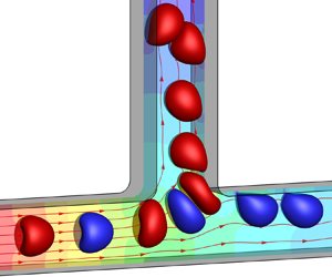
 $d=3.33a=2l$), when capsule 2 arrives at the bifurcation, capsule 1 is still around. A high lubrication pressure then builds up between the two capsules, as appears clearly from the pressure field contours shown in figure 4(a) at time $t_2$. This high pressure blocks the upwards motion of capsule 2, which can therefore only enter the downstream main channel (supplementary movie 3). At a longer initial interspacing ( $d=6.67a=4l$), capsule 1 has almost left the bifurcation at time $t_2$ when capsule 2 arrives (figure 4b). The large separation leads to interactions which are too weak to prevent the second capsule from entering the side branch (supplementary movie 4).

Figure 4. Illustration of the two interaction modes ( $a/l=0.6$, $Ca=0.1$, $Re=10$, $q=0.55$). The two capsules are shown at different times $t_1$ and $t_3$ before and after passing the bifurcation, respectively, and at time $t_2$, when the mass centre of capsule 2 is at $x=0$. The solid and dash lines are the trajectories of capsule 1 (grey) and capsule 2 (red). The colour contour represents the pressure field $pl/{\mathrm {\mu }}V$ in plane $y=0$ at time $t_2$. (a) Blocking mode ( $d=3.33a= 2l$, $Vt_1/l=-1.3$, $Vt_2/l=2.7$, $Vt_3/l=5.9$); (b) following mode ( $d=6.67a=4l$, $Vt_1/l=-0.1$, $Vt_2/l=3.8$, $Vt_3/l=7.1$). Here we define $t=0$ as the time when the first capsule reaches the bifurcation region.
The strength of the interaction between capsules can also be evaluated by the relative change in residence time, compared with the single capsule case. Figure 5 presents the effect of the initial interspacing  $d$ on the residence time of the two capsules, normalised by the residence time $t_0$ of a single capsule under the same flow conditions. It is quite interesting to see that the interaction between the two capsules has very little effect on capsule 1, whose normalised residence time is only slightly reduced compared with the single capsule case. This is true even for $d=3.33a$ where the strong interaction leads to blocking. The trajectories of the mass centre of capsule 1 at different $d$ can be found in figure 6(a), and time evolutions of the $z$-axis position of the mass centre of capsule 1 are shown in figure 6(c). The results of the two figures confirm that the motion of the first capsule is not significantly affected by the other capsule. The fine details of figure 6(c) indicate that at a same time $t$, the $z$-axis position of the mass centre of capsule 1 is larger when the initial interspacing between capsules is shorter. This arises from the fact that a shorter initial interspacing leads to a stronger interaction.

Figure 5. Residence time of the two capsules as a function of initial interspacing  $d$ at $a/l=0.6$, $Ca=0.1$, $Re=10$, $q=0.55$. The blocking mode takes place at $d=3.33a$ and the following mode prevails at $d \geqslant 5a$.

Figure 6. Trajectories of the (a) first and (b) second capsule at the channel bifurcation at different initial interspacing ( $a/l=0.6$, $Ca=0.1$, $Re=10$, $q=0.55$). The solid lines in (a,b) are the trajectories of a single capsule. Time evolution of the $z$-axis position of the mass centre of the (c) first and (d) second capsule when it is travelling through the bifurcation region. The solid lines in (c,d) are the results of a single capsule.
Compared with the first capsule, the hydrodynamic interaction, however, has a stronger effect on the motion of capsule 2. This can be seen in figure 5, where the residence time of capsule 2 is doubled when a blocking mode takes place at  $d=3.33a$. The interaction also causes the trajectory of the mass centre of capsule 2 to move further towards the downstream main channel (figure 6b) until the transition from following to blocking happens at a small initial interspacing. At the same instance, the $z$-coordinate of the mass centre of capsule 2 decreases when $d$ decreases (figure 6d).
4.3. A typical phase diagram
A typical phase diagram of capsule interaction is presented in figure 7 for two capsules with  $a/l=0.6$ at $Re=10$, $Ca=0.1$. In figure 7, the dash–dotted line marks the critical branch flow ratio ( $q_c=0.49$) of a single non-interacting capsule. The following mode is represented by circles and the blocking mode by triangles. The blocking mode tends to take place when the initial interspacing $d$ is small and/or the flow split ratio is close to the critical branch flow ratio.

Figure 7. Typical phase diagram of the interaction modes of two capsules for  $a/l=0.6$, $Ca=0.1$, $Re=10$. Triangles, blocking mode; circles, following mode; dash–dotted line, critical branch flow ratio $q_c$ for a single capsule. The dash lines represents the critical interspacing $d_{c2}$ at which the blocking-to-following transition occurs.
The critical interspacing  $d_{c2}$, which corresponds to the blocking-to-following transition for a two-capsule system (hence the index 2 in $d_{c2}$), increases sharply when $|q-q_c|$ decreases. This is linked to the fact that the residence time of a single capsule at the bifurcation region (figure 3b) increases when $|q-q_c|$ decreases. Consequently, when $q$ is near $q_c$, the first capsule spends a long time in the bifurcation region, and is therefore likely to interact with the second capsule at the corner. To avoid blocking, it is thus advisable to use a flow split ratio $q<0.4$ or $q>0.6$, depending on to which branch the capsules are to be sent.
It should be noted that when Barber et al. (Reference Barber, Restrepo and Secomb2011) studied the interaction of two-dimensional capsules at a symmetric  $Y$-shaped bifurcation, they not only observed following and blocking modes, but also identified a herding mode in which the destination of the first capsule was changed owing to interaction with the second capsule. Herding happens when the two capsules are almost in touch and are off-centred before they arrive at the bifurcation. Herding is not observed in the present study, possibly owing to the present larger capsule interspacing $d \geqslant 3.33a$ or $2l$.
$2l$.
Except for the herding mode, our results are qualitatively similar to those of Barber et al. (Reference Barber, Restrepo and Secomb2011). However, in the present study, we consider a 3-D system. We have provided a detailed analysis of the mode transition and a phase diagram relating the path-selection modes to the flow split ratio.
5. Path selection of a capsule train
The two-capsule interaction process leads to an increase of the residence time of the second capsule, which depends on the initial interspacing (figure 5). A natural question that arises is whether the increase of residence time will accumulate for a train of capsules, leading eventually to a blocking mode. We thus consider the influence of the initial interspacing  $d$ between adjacent capsules on the path selection of a capsule train consisting of identical capsules at various flow strength for capsules with different membrane shear elasticity and sizes.
5.1. Steady and unsteady regimes
For all the cases considered, we find, for a given value of  $q$, that the path selection of a capsule train is steady and stable for a sufficiently large initial interspacing $d$ but becomes unstable when $d$ decreases. This phenomenon is best illustrated for $a/l=0.6$, $Re=10$ and $Ca=0.1$, a situation for which a single capsule has a critical flow split ratio $q_c=0.49$. Figures 8 and 9 show the effect of the initial capsule interspacing $d$ on the normalised residence time $t_i/t_0$ and destination of the $i\text {th}$ capsule at flow split ratio $q=0.55$ and 0.45, respectively. Note that a single capsule flows into the side branch at $q=0.55$ but enters the downstream main channel at $q=0.45$.

Figure 8. Normalised residence time  $t_i/t_0$ as a function of capsule index $i$ with decreasing initial capsule interspacing $d$ for $a/l=0.6, Re=10, Ca=0.1, q=0.55$. Full black squares, capsules that enter the side branch; empty red squares, capsules that enter the straight branch.

Figure 9. Normalised residence time  $t_i/t_0$ as a function of capsule index $i$ with decreasing initial capsule interspacing $d$ for $a/l=0.6, Re=10, Ca=0.1, q=0.45$. Full black squares, capsules that enter the straight branch; empty red squares, capsules that enter the side branch.
When  $d$ is above a threshold interspacing $d_{ct}$ (where the index $t$ refers to ‘train’), the path selection of capsules in a train reaches a steady regime, as shown in figure 8(a) for capsules with $d=7.5a$ at $q=0.55$, and figure 9(a) for $d=11.67a$ at $q=0.45$ (supplementary movie 5). For such large values of $d$, the hydrodynamic interactions are too weak to affect the path selection of the capsules, which all take the same path as a single one would, but the trajectory is slightly different from that of a single capsule (figure 10). We then have a situation which is analogous to the following regime observed for two capsules. Compared with a single capsule, the steady-state residence time of capsules in the train has been increased by 24 % and 5 %, as shown in figures 8(a) and 9(a), respectively. Clearly the increase of residence time does not accumulate to lead to a blocking event.

Figure 10. Comparison of the steady trajectory of a capsule train with the trajectory of a single capsule at the same flow split for  $a/l=0.6$, $Ca=0.1$, $Re=10$: (a) $q=0.45$, $d=11.67a$; (b) $q=0.55$, $d=7.5a$.
When the capsule initial interspacing  $d$ is below the threshold $d_{ct}$, which is approximately $7a$ for the cases of figure 8 at $q=0.55$ and $11a$ for figure 9 at $q=0.45$, the path selection of the capsule train becomes unsteady with a succession of periodic and disordered states when $d$ is decreased. In the periodic state, the residence time of individual capsules oscillates periodically with respect to the capsule index (figures 8(b) and 9(b), supplementary movie 6). In the disordered state, the residence time oscillates irregularly with respect to the capsule index and can increase by more than two-fold from the residence time of a single capsule having the same flow conditions (figures 8(c) and 9(c), supplementary movie 7). The path selection is also erratic. This unsteady regime is somewhat different from the blocking situation of two capsules: indeed, it is difficult to predict the path of a given capsule when $d$ is smaller than $d_{ct}$. More details regarding the unsteady regime can be found in Appendix A.
5.2. Phase diagram
The phase diagram of path-selection state as a function of capsule initial interspacing and flow split ratio is shown in figure 11 for a capsule train with  $a/l=0.6$ at $Ca=0.1$, $Re=10$. The threshold interspacing $d_{ct}$ between the following and unsteady regimes increases sharply when the flow split $q$ approaches the critical branch flow ratio $q_c$. This can be expected from the results of two-capsule interaction. Note that for $d< d_{ct}$, it is very difficult to predict which regime (periodic or disordered) will occur as a very small change in $d$ for a given $q$ can lead to a change of state.

Figure 11. Path-selection states for a capsule train as a function of capsule initial interspacing and flow split ratio for  $a/l=0.6$, $Ca=0.1$, $Re=10$. Squares, following; triangles, periodic; and circles, disordered states. Black solid lines, minimum initial interspacing $d_{ct}$ for following regime; dash–dotted line, critical branch flow ratio $q_c$ of a single capsule.
We have conducted an extensive study on the effects of capsule size, flow strength and capsule membrane shear elasticity on the capsule interspacing threshold  $d_{ct}$. The results are summarised in figure 12, where $d_{ct}/a$ is plotted as a function of $q-q_c$, where $q_c$ is the critical flow split ratio for a single capsule. The values of $q_c$ for all cases in the present study are presented in table 2 in Appendix B. From figure 12 it is very interesting to find that all the data points collapse reasonably well onto a single master curve. We have also carried out simulations of capsules with a strain-softening neo-Hookean (NH) membrane (Green & Adkins Reference Green and Adkins1960), with a strain energy function given by
 \begin{equation} W = \frac{1}{2}G_s\left( I_1-1+ \frac{1}{I_2+1} \right). \end{equation}
Compared with the SK membrane, the NH law leads to slightly larger capsule deformation (not shown). However, as shown in figure 12, the results of capsule interspacing threshold  $d_{ct}$ can still be well predicted by the master curve.

Figure 12. Master curve of the threshold interspacing  $d_{ct}$ as a function of $q-q_c$.
We also consider the threshold interspacing  $d_{ct}$ normalised by the length scale $t_0V_c$, where $V_c$ is the steady velocity of a capsule in the feeding channel and $t_0$ is the capsule residence time in the bifurcation. Figure 13 shows that $d_{ct}/t_0V_c$ is always below unity. An initial interspacing of $t_0{V_c}$ can, therefore, be used to guarantee that the capsules in the train are in the steady regime. It corresponds to the case where a capsule arrives in the bifurcation region when the previous one leaves the region. We thus conclude that capsule interactions are too weak to affect their path selection when there is only one capsule in the bifurcation region at any time.

Figure 13. Threshold interspacing  $d_{ct}$ normalised by the length scale $t_0V_c$ as a function of $q-q_c$. Symbols in the figure are the same as those in figure 12.
6. Discussion
6.1. Comparison with a two-capsule system
The threshold interspacing  $d_{ct}$ of a capsule train is compared with the critical $d_{c2}$ of a two-capsule system for the same flow conditions ( $a/l=0.6$ at $Re=10$ and $Ca=0.1$) in figure 14. Because $d_{ct}$ is always higher than $d_{c2}$, it would be misleading to use the results from the two-capsule model to determine the minimum interspacing necessary to obtain a following regime in a train. This shows that the full capsule train analysis is necessary to be able to control the path selection of a train.

Figure 14. Comparison of the threshold initial interspacings of the two-capsule system and the capsule train ( $a/l=0.6$, $Re=10$ and $Ca=0.1$). Black solid line, $d_{ct}$ for a capsule train; dash line, $d_{c2}$ for two capsules; dash–dotted line, $q_c$ of a single capsule.
6.2. Relevance to experiments
The present study provides practical guidelines for experiments, in which bifurcated channels are used for capsule sorting or enrichment. We find that using a straight channel with a right-angled side branch is robust as long as hydrodynamic interactions between capsules in the train are too weak to affect the path-selection process. The model presented in the previous section will be useful to experimentalists to estimate the minimum interspacing to set between capsules in the feeding channel and ensure that capsules with the same properties have the same destination.
To maximize the number of capsules, it will be interesting to run the process with a capsule interspacing as close as possible to the critical value  $d_{ct}$. Indeed, the volume fraction of capsules in the suspension is a direct function of $d$. Many microfluidic cell enrichment devices (Hur et al. Reference Hur, Henderson-Maclennan, McCabe and Di Carlo2011; Warkiani et al. Reference Warkiani, Khoo, Wu, Tay, Bhagat, Han and Lim2016) are typically operated with a cell volume concentration much lower than $1\,\%$ to avoid cell interactions. However, our study shows that the present bifurcated channel can be run at much higher volume fractions. For instance, if one enriches a capsule suspension in a microchannel such that $a/l=0.6$, $Ca=0.1$, $Re=10$ and $q=0.55$, the 3-D LB simulations predict $d_{ct}=7.58a$, which corresponds to a capsule volume fraction in the feeding channel of $8.3\,\%$. This shows the potential offered by a device as simple as a microfluidic channel with a right-angled side branch for sorting or enrichment applications. Note that various techniques, such as surface acoustic waves (Wood et al. Reference Wood, Evans, Cunningham, O'Rorke, Wälti and Davies2008) or inertial flows (Lee et al. Reference Lee, Amini, Stone and Di Carlo2010; Kahkeshani, Haddadi & Di Carlo Reference Kahkeshani, Haddadi and Di Carlo2016), have been developed to organise particles following in a microchannel into trains with controlled interspacing. These techniques can be employed with the present branched channel platform to process suspensions with high concentration of capsules.
When enriching capsule suspensions, it is also desirable to operate the microfluidic device at a flow split ratio close to  $q_c$, so that capsules can be captured with as little suspending fluid as possible in the chosen daughter branch. However, if $q \sim q_c$, the master curve of $d_{ct}$, provided in figure 12, shows that a long initial capsule interspacing is needed to avoid capsule interaction at the bifurcation. There is thus a compromise to be found when choosing the flow split ratio $q$ and the capsule interspacing $d$ to optimize the capsule concentration in the chosen daughter branch and thus the device throughput. Let $\phi$ be the fraction of capsules of the train that enter the side channel. Figure 15 shows different values of $d$ and $q$ under the same conditions as those of figure 11 ( $a/l=0.6$, $Ca=0.1$ and $Re=10$), for which a single capsule has a critical flow split ratio $q_c=0.49$. When $q$ is close to $q_c$, the capsule fraction $\phi$ remains constant over a large range of values of $d$. It then quickly reaches zero or unity depending on $q$, when $d \lesssim d_{ct} - 3a$. When the flow split ratio is far away from $q_c$, $\phi$, however, changes almost linearly with the capsule interspacing $d$. Figure 15 will help experimentalists choose the values of $q$ and $d$ depending on the capsule fraction that can be tolerated in the other branch.

Figure 15. Fraction  $\phi$ of capsules entering the side channel as a function of the initial interspacing $d$ at $a/l=0.6$, $Ca=0.1$, $Re=10$. Full symbols correspond to the steady states; empty symbols correspond to the unsteady states.
Most simulations of the present study have been conducted at a flow Reynolds number  $Re=10$ where there is a finite inertial effect. The condition is relevant to the flow of artificial capsules with a polymerized albumin membrane, which typically have a radius in the range of $30 - 200\ \mathrm {\mu }\textrm {m}$ (Lefebvre et al. Reference Lefebvre, Leclerc, Barthès-Biesel, Walter and Edwards-Lévy2008; Chu et al. Reference Chu, Salsac, Leclerc, Barthès-Biesel, Wurtz and Edwards-Lévy2011; de Loubens et al. Reference de Loubens, Deschamps, Georgelin, Charrier, Edward-Lévy and Leonetti2014; Gubspun et al. Reference Gubspun, Gires, de Loubens, Barthès-Biesel, Deschamps, Georgelin, Léonetti, Leclerc, Edwards-Lévy and Salsac2016). If we flow such capsules with $a=60\ \mathrm {\mu }\textrm {m}$ in a channel with a half-side length of $l = 100\ \mathrm {\mu }\textrm {m}$ ( $a/l=0.6$), using a fluid with $\mu =0.01\ \textrm {Pa}\ \textrm {s}$ and $\rho =1000\ \textrm {kg}\ \textrm {m}^{-3}$, a flow Reynolds number of $Re=10$ can be achieved when the flow speed averages $0.5\ \textrm {m}\ \textrm {s}^{-1}$. In a straight channel, this corresponds to a pressure drop of 35.2 kPa per centimetre channel length. For polymerised albumin capsules with $a=60\ \mathrm {\mu }\textrm {m}$, a reasonable value of membrane shear elasticity is $G_s \sim 0.05\ \textrm {Nm}^{-1}$ (Chu et al. Reference Chu, Salsac, Leclerc, Barthès-Biesel, Wurtz and Edwards-Lévy2011; de Loubens et al. Reference de Loubens, Deschamps, Georgelin, Charrier, Edward-Lévy and Leonetti2014), which leads to $Ca/Re=0.01$. We have also considered flows with $Re=1$ and 40. Note that our earlier work (Wang et al. Reference Wang, Sui, Salsac, Barthès-Biesel and Wang2016, Reference Wang, Sui, Salsac, Barthès-Biesel and Wang2018) has suggested that at $Re=1$ the effect of inertia on capsule path selection is negligible. As shown in figure 12, which plots $d_{ct}/a$ as a function of $q-q_c$, inertia does not significantly affect the master curve when $Re \leqslant 40$.
It is also worth mentioning that in channel flow, inertia has been found to cause suspended rigid or deformable particles to migrate from the channel centreline (Chun & Ladd Reference Chun and Ladd2006; Di Carlo Reference Di Carlo2009; Kilimnik, Mao & Alexeev Reference Kilimnik, Mao and Alexeev2011). The off-centre motion is less pronounced for deformable particles because deformation enhances a lift force that drives particles towards the channel centreline. In the present study, we have considered capsules that are initially centred on the channel centreline. In experiments this can be achieved by using some upstream flow-focusing modules (Nawaz et al. Reference Nawaz2014; Vesperini et al. Reference Vesperini, Chaput, Munier, Maire, Edwards-Levy, Salsac and Le Goff2017). We have not observed any off-centre migration in the parent channel in all cases considered.
7. Conclusion
The present work is the first systematic 3-D computational study of the path selection of a train of spherical capsules flowing through a branched microfluidic channel. To understand the hydrodynamic interaction between capsules and interpret the path selection of a capsule train, we have also considered a pair of capsules in the same channel bifurcation. We find that capsule interaction crucially depends on the capsule interspacing in the feeding channel and the flow rate split ratio at the bifurcation. Generally a shorter capsule interspacing and a flow split ratio that is closer to the critical value at which a capsule becomes stuck at the bifurcation will lead to stronger capsule interaction in the channel bifurcation region. Interestingly, our results suggest that the interaction has little effect on the first capsule of the pair, however, it can significantly retard the motion of the second capsule. This can be quantified by the ratio of a capsule residence time in the channel bifurcation to that of a single non-interacting capsule. With the decrease of the capsule interspacing, the ratio of the residence time of the second capsule increases, which suggests a stronger retarding effect, till the second capsule gets blocked by the first one and enters a different downstream branch. This interesting phenomenon provides the foundation to understand the path selection of a capsule train in the channel bifurcation.
For a capsule train flowing through the bifurcation, a natural question that arises is whether the retarding effect from capsule interaction on a following capsule will accumulate in the capsule train. Our path selection phase diagrams, obtained from extensive numerical simulations covering capsules with different sizes, membrane laws and shear elasticity, capsule interspacing, and at various flow strength and flow split ratios, suggest that there are mainly two path-selection regimes. The regimes are separated by a critical initial interspacing  $d_{ct}$, which depends on flow conditions and capsule properties. When the initial interspacing is above $d_{ct}$, capsule interaction is not strong and its effect does not accumulate. The capsules adapt to a new steady trajectory which is very close to that of a single non-interacting capsule. Therefore capsule interaction does not have any effect on capsule destination. However, when the capsule interspacing is below $q_c$, the effect of strong capsule interaction accumulates and leads to an unsteady regime where capsules are frequently blocked by those flowing ahead and enter a different downstream branch.
Interestingly we find that the interspacing threshold  $d_{ct}$, normalised by the capsule radius, at various flow split ratios and strength, for capsules with different sizes and membrane shear elasticity, falls into the same master curve. We also find that the critical interspacing $d_{ct}$ is always less than the length scale of $t_{0}V_{c}$. The present study provides useful guidelines to avoid strong capsule interaction in experiments where branched microchannel bifurcations are used for sorting or enriching suspensions.
Supplementary movies
Supplementary movies are available at https://doi.org/10.1017/jfm.2021.571.
Funding
R.X.L. acknowledges a PhD studentship provided by Queen Mary University of London (QMUL) and the Chinese Scholarship Council. The simulations were performed using the high-performance computer clusters of QMUL (funded by the UK EPSRC grant EP/K000128/1). This work was also supported by the European Research Council (ERC) under the European Union's Horizon 2020 research and innovation programme (grant agreement no. ERC-2017-COG – MultiphysMicroCaps).
Declaration of interests
The authors report no conflict of interest.
Appendix A. Unsteady path-selection regime of the capsule train
The unsteady regime of the capsule train arises from an accumulation of the effect of capsule interaction. Compared with a non-interacting capsule, a longer residence time  $t_{i}$ of the $i\text {th}$ capsule in a train results from the hydrodynamic interaction with the $(i-1)\text {th}$ capsule, which causes an apparent reduction of the initial interspacing between the $i\text {th}$ and $(i+1)\text {th}$ capsules. This leads to an even longer residence time of the $(i+1)\text {th}$ capsule. The increase of residence time accumulates, until the triggering of a blocking event, which is the feature of the unsteady path-selection regime of the capsule train.
In the unsteady regime, the path selection of the capsule train may be periodic or disordered. Figure 16(a) shows the trajectories of individual capsules in the periodic state for  $a/l=0.6$, $Ca=0.1$, $Re=10$, $q=0.45$, $d=10.33a$, which corresponds to figure 9(b). The five represented capsules (i.e. from the $20\text {th}$ to the $24\text {th}$) form a periodic group and their normalised residence time increases with the capsule index, as can be seen from the small figure inset. The time evolution of the $z$-coordinate of the capsule mass centres are presented in figure 16(b). From the $20\text {th}$ to the $23\text {rd}$ capsule, the trajectory of the capsule moves gradually towards the side branch. The highest $z$-coordinate that the mass centre of a capsule can reach also increases with the capsule index. Figure 17(a–f) presents the instantaneous profiles of the capsules starting from the $19\text {th}$ one, when they are leaving the bifurcation region. It is clear from figure 17(b–e) that the distance between one capsule leaving the bifurcation and the following one is decreasing, which results in stronger capsule interaction in the bifurcation region. Not surprisingly this leads to a blocking event, which takes place on the $24\text {th}$ capsule. Note that the gradual decrease of the interspacing between capsules near the bifurcation in figure 17(b–e) arises from the increase in residence time of the capsule that is leaving the bifurcation.

Figure 16. Periodic state: (a) trajectories of individual capsules forming a periodic group for  $a/l=0.6$, $Ca=0.1$, $Re=10$, $q=0.45$, $d=10.33a$, corresponding to figure 9(b). The figure inset shows the evolution of the capsule residence time $t_i/t_0$ with respect to capsule index; (b) time evolution of the $z$-coordinate of the mass centres of capsules in (a).

Figure 17. Capsule profiles when the (a) 19th, (b) 20th, (c) 21st, (d) 22nd, (e) 23rd and ( f) 24th capsule leaves the channel bifurcation, in the periodic state shown in figure 16. The time instances for (a–f) are 79.2, 81.5, 86.1, 90.2, 95.1 and 97.9, respectively.
Figure 18(a,b) shows the capsule trajectories and  $z$-coordinate of their mass centres in the disordered state for $a/l=0.6$, $Ca=0.1$, $Re=10$, $q=0.45$, $d=9a$, which corresponds to figure 9(c). Similar to the previous case, the 20th to 22nd capsules form a group on track to a following-to-blocking transition. However, two capsules (the 22nd and 23rd) are this time trapped at the bifurcation, which affects the motions of the following few capsules (see figure 18 and the instantaneous capsule profiles in figure 19) and disrupts the regularity of the path selection of the capsule train.

Figure 18. Disordered state: (a) trajectories of individual capsules for  $a/l=0.6$, $Ca=0.1$, $Re=10$, $q=0.45$, $d=9a$, which corresponds to figure 9(c). The figure inset shows the evolution of the capsule residence time $t_i/t_0$ with respect to capsule index; (b) time evolution of the $z$-coordinate of the mass centres of capsules in (a).

Figure 19. Capsule profiles when the 22nd or 23rd capsule is near the channel bifurcation in the disordered state shown in figure 18. The time instances for (a–d) are 82.4, 84.2, 87.8 and 92.1, respectively.
Appendix B. Values of $q_c$

Table 2. Values of  $q_c$ of all cases.

Appendix C. Immersed boundary–lattice Boltzmann method
In the lattice Boltzmann method (LBM), fluid is treated as fictive particles that collide and spread along discrete directions at each spatial position. The distribution function  $f_i(\boldsymbol {x}, t)$ is the main quantity in LBM. It gives the probability of finding a particle having lattice velocity $\boldsymbol {e}_i$ at position $\boldsymbol {x}$ and time $t$. The discrete lattice Boltzmann equation for the D3Q19 model used in this study reads (Bhatnagar, Gross & Krook Reference Bhatnagar, Gross and Krook1954; Guo et al. Reference Guo, Zheng and Shi2002)
 \begin{equation} f_i(\boldsymbol{x}+\boldsymbol{e}_i\Delta t, t+\Delta t)-f_i(\boldsymbol{x}, t)={-}\frac{1}{\tau}[\,f_i(\boldsymbol{x}, t)-f_i^{eq}(\boldsymbol{x}, t)]+\Delta tF_i, \end{equation}
where  $\Delta t$ is the time step, $f_i^{eq}(\boldsymbol {x}, t)$ is the equilibrium distribution function, $\tau$ is the non-dimensional relaxation time related to the fluid viscosity and $F_i$ is the forcing term related to the fluid body force density $\boldsymbol {f}(\boldsymbol {x},t)$ (Guo et al. Reference Guo, Zheng and Shi2002). The macroscopic quantities (e.g. velocity, pressure) can be obtained from the particle distribution function. The lattice Boltzmann equation can recover the incompressible Navier–Stokes equations through the Chapman–Enskog expansion.
The immersed boundary method (IBM) of Peskin (Reference Peskin1977) has been used to solve the fluid–capsule interaction. In IBM, the no-slip boundary condition on the capsule membrane is satisfied by letting the membrane nodes move at the same velocity as the fluid around it. This will cause the capsule to deform. The body force density induced by the membrane on the fluid is obtained from distributing membrane forces by
 \begin{equation} \boldsymbol{f}(\boldsymbol{x},t)=\int_S (\,\boldsymbol{f}_e+\boldsymbol {f}_b)\delta(\boldsymbol{x}-\boldsymbol{x}')\,\textrm{d}\kern0.7pt\boldsymbol{x}', \end{equation}
where  $\boldsymbol {f}_e$ and $\boldsymbol {f}_b$ are the elastic and bending force densities of the capsule membrane, respectively. The terms $\boldsymbol {x}'$ and $\boldsymbol {x}$ represent the coordinates of the membrane and fluid nodes, respectively. The 3-D smoothed Dirac delta function is chosen to be
 \begin{equation} \delta(\boldsymbol{x}-\boldsymbol{x}')=\delta(x-x')\delta(y-y')\delta(z-z'), \end{equation}
where
 \begin{equation} \delta(r)=\begin{cases} \dfrac{1}{4}\left(1+\cos\left(\dfrac{{\rm \pi} |r|}{2\Delta x}\right)\right) & |r|\leqslant 2\Delta x.\\ 0 & \textrm{otherwise}. \end{cases} \end{equation}
The same Dirac delta function is used to obtain the velocity of capsule membrane nodes by interpolating the local fluid velocity.
In the present simulations the volume change of individual capsules is always less than 1 %. We have not used any additional algorithm to conserve the capsule volume.


 Open access