

Introduction
Friction of ice against the hull of a ship is an important factor in the resistance of an icebreaking ship (Reference Jones, Sinha, Sodhi and ChungJones, 1989; Reference Liukkonen, Ayorinde, Sinha, Sodhi and NixonLiukkonen, 1992). During model tests it is routinely measured by all ice tanks and used as a correlation factor when comparing model-scale results to full-scale. Friction is also important in such diverse area as glaciers sliding on bedrock at very low speeds, and skiing or skating at very high speeds. Often, an icebreaking ship hull slides against wet ice so the interface is essentially at, or close to, the melting point. Consequently ice tanks usually measure the friction of wet model ice, which is slowly melting, for comparison with full-scale results, usually at speeds of about 0.2 ms−1 (Reference Bell and NewburyBell and Newbury, 1991).
The present work was designed to measure the friction coefficient of melting ice against materials of different thermal conductivity. By choosing pure ice rather than sea ice or model ice, we hoped to simplify the physics of the problem by eliminating the brine. We were able to cover a wide range of velocities, from 0.05 to 400 mm s−1, which extends from that of surging glaciers at the low end, to that of model ship tests in ice tanks, and full-scale ice-structure interactions found in nature at the other. The work was performed at the Ship Research Institute, Tokyo, Japan, while the senior author was a guest worker there, and lack of lime prevented completion of all the planned experiments. This paper summarizes the results obtained.
Method
A schematic drawing of the friction test set-up is shown in Figure 1. The ice sample was fixed in position and the friction plate moved underneath it. The path length was usually 760 mm, except for the very slow tests when it was shorter, and tests ranged from 4 hours to 2 seconds, corresponding to speeds of 0.05 to 400mm s−1. The frictional force acting on the ice sample was measured by a load cell of capacity 10 kgf which was placed between a supporting frame and the sample. The normal force was a deadweight, which could be varied from 0 to 50 kg, but which was kept constant at 10 or 20 kg for the majority of the tests. The weight of the supporting frame, load cell and ice sample was eliminated by means of a counter weight.

Fig. 1. A schematic diagram of the friction test apparatus.
The friction plates were 1 m long, 0.3 m wide, and 30 mm thick. Four friction plates were tested: aluminium, acrylic, copper, and a plate coated with a melamine resin, tradename Formica. Other plates were built bul not tested in the time available. The surface roughness of the plates was measured by a Surface Texture Measuring Instrument (Tokyo Seimitsu, model Surcom 550A) using a replica of a small part of the surface, made by pouring a cold-curing resin with a methylmethacrylate base (Kulver, Technovit 3040) on to the plate and waiting for it to dry. An example of a surface profile is shown in Figure 2 for the aluminium plate. In this paper, the average roughness, Ra , given by the following equation, is taken as an index of the surface roughness of a plate.

Fig. 2. An example of the roughness results obtained from a replica of the aluminium plate.
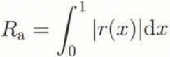
where 1 is the length of roughness measurement, r(x) is the roughness height at distance x measured from the average level over 1. The roughness meter used in this study has an accuracy of 0.02 μm in terms of the average roughness.
The signal from the frictional force load cell was amplified and recorded on magnetic tape, which was also digitized and analyzed simultaneously by a desk top computer. An example of the time history of the frictional
force is shown in Figure 3. As seen in this figure, there is a steady signal of the kinetic friction, preceded by a high peak, due to static friction, at the beginning. Assuming Coulomb’s law to be applicable, friction coefficient μ was calculated as μ = F/N, where F is the average frictional force over the steady state, the kinetic friction, and Ν is the normal force. In this paper we ignore the static friction coefficient.

Fig. 3. An example of the time history of the frictional force obtained for the Formica friction plate, at a speed of 0.5 mm s−1. The friction coefficient was the average force between the vertical lines at times of 75 and 1400 s, divided by the normal force.
Air temperature in the room — the trim dock area of the ice tank — was maintained at + 2 ± 1°C. Temperature control was by the opening and shutting of the ice tank door, so occasionally the temperature rose somewhat before we realised what had happened. The sample was, therefore, always melting slowly during the tests. The only exception to this was one set of tests done at −3°C, on a copper plate, in order to compare with literature values of friction coefficient.
Ice samples were prepared from distilled, de-aerated water frozen in plastic containers insulated at the sides and bottom, in a freezer at −15°C. They were not seeded but were allowed to freeze naturally. The grain structure of the bulk of the ice was columnar with a grain size of approximately 5 mm, and the part of the samples from near the bottom and sides of the container was cut away with a band saw. The end result was a sample approximately 150 × 100 × 30 mm with friction surface of 150 × 100 mm, and columnar grains perpendicular to the friction surface. The samples were frozen into a brass holder which was then attached to the friction apparatus and allowed to sit at room temperature for some time, approximately 30–60 min, until the sample was slowly-melting.
Immediately prior to testing, the sample and the friction surface were dried with absorbent tissue paper. After a test, the water formed on the plate was mopped-up with another piece of tissue paper which had been weighed. The wet tissue was then weighed and the weight of meltwater produced was determined.
Result
General results
Tests were conducted on aluminium, copper, Formica and acrylic plates. Their roughness values, as measured by us, and thermal conductivities at 273 K, from reference books, are given in Table 1.
Unfortunately, the roughness of the acrylic sheet was not measured but it was much smoother than the Formica as judged by feel, and probably had a roughness close to a glass plate, which we did measure, and which had an Ra of 0.02, or just at the accuracy limit of the equipment. Our original intent was to have all surfaces of identical roughness, but this was not possible. However, the aluminium and Formica plates were similar in roughness, but very different in conductivity, and so were studied the most. The Formica and acrylic plates were similar in thermal conductivity, but different in roughness. The copper plate was used only for some tests at −3°C, for comparison with literature values of friction coefficient.
Table 1. Results of roughness values and reported thermal conductivity for materials used

Meltwater produced
Observations of the friction surface after a test showed that at high speeds water droplets were dragged along by the moving plate, but at slow speeds all the meltwater
remained with the ice sample, held in place by surface tension. This transition occurred at approximately 50 mm s−1.
The amount of meltwater produced depended greatly on the thermal conductivity of the slider as can be seen by-comparing Figures 4(b) and 5(b), with the higher thermal conductivity aluminium producing almost ten times more water than the Formica. It was also a strong function of velocity as can be seen in the figures, with the amount of meltwater increasing dramatically between about 10 and 100 mm s−1.

Fig. 4. Friction coefficient (a) and meltwater produced (b) for the aluminium plate as a function of velocity, for a normal pressure of 7kPa.

Fig. 5. Friction coefficient (a) and meltwater produced (b) for the Formica plate, normal pressure 14kPa.
Copper
Tests were conducted on a copper plate with air temperature maintained at −3°C, principally to compare with results obtained by Reference Evans, Nye and CheesemanEvans and others (1976). Our values for friction coefficient, μ not shown, were essentially constant over the range 0.5–400 mm s−1 at 0.028 ± 0.005, for a normal pressure of 7 kPa, compared to a value of 0.035 extrapolated from Reference Evans, Nye and CheesemanEvans and others I 1976), under similar conditions.
Aluminium
Figure 4(a) shows the results obtained for three different ice samples on the same aluminium plate, and Figure 4(b) shows the corresponding amounts of meltwater produced for each test. Similar results were obtained on a different day at a higher normal pressure, 14kPa, as against 7 kPa for Figure 4. The general pattern was as for Figure 4; a gradual increase in friction coefficient with velocity, v, from the slowest speed to a maximum at v = 10 mm s−1 followed by a decrease to v = 100mm s−1 and then another increase. The results were more scattered at the highest speeds, above 30 mm s−1, while it was always possible to obtain good agreement with different ice samples tested on different days at speeds slower than this. Agreement between the two sets of measurements, Figure 4 and those at 14kPa (not shown), was good except in the speed range 10–40 mm s−1, where the tests at the higher normal load gave somewhat lower friction coefficients, and also at the very highest.
Formica
Figure 5 shows results for two sets of tests (on different days) on the same Formica sheet. The results are consistent at speeds below 30mm s−1, but above this speed, results show much greater scatter. As can be seen in Figure 5(b), it is just at this speed that the amount of meltwater produced starts to increase dramatically. At high speeds, 100 mm s−1 and up, the friction coefficient seems to level off, rather than go through a minimum as was the case with the aluminium plate, and there is again considerable more scatter in the results. The peak in the friction curve is shifted to a slightly lower value of velocity, 4mm s−1, as opposed to 10mm s −1 for aluminium, and the value of the Formica/ice friction coefficient is about twice that of the aluminium: this, for plates of a similar roughness but very different thermal conductivities. The amount of meltwater produced is much less for the Formica than the aluminium; note the very different scales in Figures 5(b) and 4(b). However, the shape of the curves are the same, with little meltwater being produced until speeds of about 30 mm s−1 are reached.
Acrylic
Figure 6 shows results for an acrylic sheet, much smoother than the Formica but of similar thermal conductivity. Here the friction values are much smaller, by a factor of 10, and therefore subject to bigger errors, essentially because one is trying to measure small loads with a large load cell. There is a suggestion of a maximum at a velocity of about 2 mm s−1, but the scatter of the results is too great to justify this, except in comparison to the Formica and aluminium results. The meltwater produced was comparable to the Formica, but slightly greater except at speeds above 70 mm s−1. This is because although the friction coefficient was much smaller, the thermal conductivity of acrylic is similar to Formica and it is the thermal conductivity that is controlling the amount of meltwater.

Fig. 6. Friction coefficient (a) and meltwater produced (b) for the acrylic plate, normal pressure 7 kPa.
Discussion and Conclusions
Previous work
The results obtained on the copper plate at −3°C were consistent with literature values, and so confirmed that we were obtaining reliable results.
Our results are different from most friction results in the literature, but almost no-one has studied the friction of ice at the melting point. Reference Barnes, Tabor and WalkerBarnes and others (1971) obtained results which at first sight look like ours, namely a bell-shaped curve, but under very different conditions, well below the melting point. They interpreted their results in terms of creep at low speeds, plastic flow and fracture at the medium speeds and frictional heating and melting at high speeds. Clearly there is no creep, plastic flow or fracture in the present experiments so the similar appearance of the results is fortuitous.
For sea ice at −8°C, and a similar speed range, Reference Saeki, Ono, Nakazawa, Sakai and TanakaSaeki and others (1984) gave results for concrete, and coated and uncoated steel. All showed a decrease in friction coefficient as speed was increased from 0.3 to 10mm s−1, followed by a levelling off and an essentially constant friction to the highest speeds measured, 1000 mm s−1. Reference Oksanen and KeinonenOksanen and Keinonen (1982) studied ice at −1°C and lower temperatures but only over a narrow speed range, 500–3000 mm s−1, at the upper end of our range. Reference Evans, Nye and CheesemanEvans and others (1976) studied ice friction in the range of 200–10000 mm s−1, between −15° and −1°C. They found that μ was proportional to temperature below the melting point and to v −1/2. This is expected when the friction is controlled by thermal conduction into the slider and ice, and little heat is used to melt ice. However, in our-case this is not true, heat is being conducted into the ice from the surroundings which are warmer than the ice, and heat generated at the interface will also melt ice. In this case, Reference Oksanen and KeinonenOksanen and Keinonen (1982) have shown that μ, as well as the thickness of the water layer, should be proportional to v 1/2.
Our results
In our experiments we have to explain an increase in μ with v, followed by a maximum, a decrease, and then a levelling off, or possibly another increase. At the very lowest speeds there is sufficient heat conduction through the plates to melt enough ice to cover all the asperities on the plate surface, thus giving a very low friction coefficient. This can be shown by a simple calculation from the measured amount of meltwater, and the roughness of the plates. The rise of μ with velocity up to the maximum does indeed follow approximately a v 1/2 dependence, as shown in Figure 7(a) for Formica, where the results are plotted on a log-log scale. Also, the amount of meltwater produced follows a similar dependence in this range, and continues the same dependence somewhat beyond the friction coefficient maximum, as shown in Figure 7(b) for aluminium. This rise of μ with velocity is due to increased ice-plate direct contact, with the water film being squeezed out with increasing speed. However, another mechanism must cause the maximum to occur,

Fig. 7. Friction coefficient for Formica (a) and meltwater produced for aluminium (b) plotted against velocity on a log-log scale. A line of slope 1/2 is shown, corresponding to ![]() .
.
and the subsequent decrease in μ with v. We believe that the maximum occurs because the amount of meltwater generated by thermal conduction through the plate to the interface increases dramatically, and eventually becomes so large that the asperities in the plate are again covered with water, thus reducing the frictional force to a low value. For aluminium, with the much larger amount of meltwater, the friction is then reduced to a very low value, whereas with Formica, and less meltwater, the friction is not reduced as much. For the acrylic plate, which was much smoother, the amount of meltwater required to cover the asperities was much less, and was essentially provided by thermal conduction at all speeds.
The reason that the amount of meltwater is a strong function of velocity is that at high speed, the ice is always in contact with a warm plate at +2°C, whereas at low speeds the melting ice cools down the plate. Also, as noted above, the meltwater (at 0°C) stays in contact with the ice at low speeds, below 50 mm s−1, thus acting as a thermal mass which must be warmed by conduction through the plate before more melting can occur. Above 50 mm s−1, where the meltwater is dragged along by the sliding plate rather than always being in contact with the ice, there is no meltwater to warm before more melting can occur. Heat generated by friction would also aid melting, but this can be shown to be negligible compared to the heat conducted through the plate.
The final increase in μ at high speeds for the aluminium, or the levelling off for the Formica, is, we believe, due to viscous drag of the very large amount of meltwater now being produced.
Implications of Results
Ice tanks usually measure the friction coefficient of their model ice against their ship model at speeds of about 200 mm s−1, because these are the scaled speeds of icebreaking ships. This is, perhaps, unfortunate because the present results in this range show considerable more scatter than at lower speeds, and a dependence of friction on the thermal conductivity of the slider. However reproducible results are achieved at a given tank, and even when different tanks test the same friction plate (Reference Bell and NewburyBell and Newbury, 1991). This is probably because the roughness of a typical model is much greater than the plates used here, with consequently higher friction coefficients.
Surging glaciers slide on their beds at speeds of the order of the slow speeds reported here, 0.1 mm s−1 or 3 km a−1. These results show that in this range the friction coefficient starts to rise with speed, which could possibly act as a negative feedback mechanism tending to prevent further acceleration of the glacier.
Full-scale ice/structure interactions, for example ice against bridge piers, drilling rigs etc., occur at speeds of 10–1000 mm s−1. In this range, we have shown that the friction coefficient can vary considerably with different amounts of meltwater, although for design purposes this may not be relevant because design loads would be calculated using significantly larger friction coefficients corresponding to lower temperatures. Also, full-scale structures, whether made of concrete or steel, would have significantly rougher surfaces than those used in this work, which would also increase the friction.
Acknowledgements
The senior author would like to thank the Ship Research Institute, Japan, for inviting him to work there for eight months in 1987–88, and for treating him in a manner to which he would like to become accustomed. He is also grateful to the National Research Council of Canada for allowing him to go. All the authors are grateful for support from the Japan Ship and Ocean Foundation.


