


Introduction
While small by Antarctic standards, Sørsdal Glacier (68°42’ S, 78°30’ E) is the largest of a number of outlet ice streams that contribute to the discharge of the East Antarctic ice sheet from Princess Elizabeth Land and Wilhelm I I Land into Prydz Bay (Fig. 1). Observations from existing aerial photography indicate that the Sørsdal contains significant regions of ice that contain zones of anomalously high flow rates and localized strain juxtaposed to regions where the surface is characterized by either planar, en echelon or sigmoidal fracture patterns. This paper is part of a detailed study of glacier dynamics to gather information regarding the relationship of strain rate and/or dilation to fracture initiation and propagation in a fast-flowing polar ice stream.

Fig. 1. Map of project area, Vestfold Hills/Sørsdal Glacier region, East Antarctica, showing the locations of the Russian Fuel Depot (RFD), Christensen (CTSN) and Ingrid (ING) grids. Also shown are the locations of the Doris site and rock-mounted survey control points.
During the 2000/01 season, three high-density strain grids, totalling 254 markers, were established on the glacier surface to provide reference for ice-monitoring surveys. The strain grids were located at accessible regions along the northern marginal shear zones (Fig. 1) where large velocity gradients exist. These are indicated by the transition from stagnant blue ice through to zones of compound crevasse traces and active crevasses. These shear zones mark the boundary of the Sørsdal ice stream against the adjacent ice plateau. The areas investigated are situated in the ablation zone, and upstream of the grounding line, at elevations of 180–460ma.s.l. (Fig. 2). Velocity fields at each strain grid have been computed using the available temporal survey data collected using the stop-and-go global positioning system (GPS) technique during two field seasons. The results show ice-flow rates increasing exponentially from 2 ma–1 to 61 ma–1 over a 2 km reach of ice at the Sørsdal Glacier margin. The highest velocity measured was 123 m a–1 at an isolated survey site a further 700 m south into the ice stream.
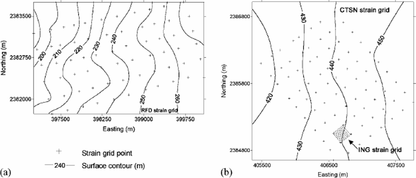
Fig. 2. The three strain grids established on Sørsdal Glacier: (a) the RFD grid, and (b) the CTSN and ING grids. The spatial resolution of the ING strain grid can be clearly seen. Strain markers are referenced to the UTM (GRS80) grid coordinate system, zone 44.
The velocity gradients at each strain grid have a good spatial correlation with field observations and sketch maps showing the occurrence of brittle and ductile deformation features (e.g. active crevasses occur where there is a significant increase in the velocity gradient). Strain-rate tensors computed at 64 regularly spaced points, at an interval of 20 m, are found to match the crevasse pattern in this study area. The close agreement between the crevasse pattern and the strain-rate tensors provides evidence that the crevasses are local and transient in nature, which is also supported by direct field observations. In a similar study, Reference Harper, Humphrey and PfefferHarper and others (1998) concluded that surface-flow features, reflecting conditions of strong shear and fast flow, could prove useful for mapping the strain-rate tensor. The detailed velocity measurements and structural observations of local ice flow on Sørsdal Glacier, which are the highest-spatial-resolution recordings of ice flow known to the authors, support Harper’s findings.
A DORIS (Doppler Orbitography and Radiopositioning Integratedby Satellites) beacon was also deployed on Sørsdal Glacier during the 2001 season, allowing ice movement to be measured at a fine temporal and spatial resolution (Fig. 3). DORIS comprises a permanent network of satellites (the orbitography network) equipped with receivers capable of measuring the Doppler shift on signals emitted from ground units to a high accuracy. The ground units broadcast signals on two frequencies so that ionosphere-induced errors can be reduced during post-processing. The receivers are currently placed on board SPOT2, SPOT4 and Topex-Poseidon satellites (http://www.ing.fr/fr/PI/activities/geodesite/DORIS/index-en. html). Measurements made by the receivers are downloaded to visible control stations where the data are processed to determine the precise trajectory of the satellite(s).

Fig. 3. The DORIS unit on Sørsdal Glacier. In the background is the DORIS transmitting antenna. This is connected via cables to the solar panel array seen in the foreground. This was located at 68.637° S, 78.718° E.
The orbit computations are then used to calculate the exact positions of individual ground units, such as the beacon placed on Sørsdal Glacier. The DORIS ground network comprises more than 50 evenly distributed stations worldwide with precisely determined coordinates. The positional accuracies achievable by DORIS allow for its current use in several important geodetic applications including tectonic monitoring and contributing to the determination of the terrestrial reference system of the Internal Earth Rotation Service. DORIS is promoted for deformation monitoring applications in high-risk (and remote) areas where continually acquired data can be processed remotely on a permanent basis, i.e. daily, weekly, monthly, etc.
Strain Grids
Ice-flow velocities were determined by monitoring the movement of three strain grids emplaced in the surface of the glacier. Each grid comprises a geometric network of aligned 6 m bamboo canes, inserted to a depth of 1 m in the glacier surface (Table 1). The strain grids for this project are referred to as Russian Fuel Depot (RFD), Christensen (CTSN) and Ingrid (ING) (Fig.1.). The layout of each strain grid is shown in Figure 2. Individual markers within the grid network are identified by a unique reference, which is engraved onto an attached copper plate.
Table 1. Dimensions of the strain grids on Sørsdal Glacier

The strain grids were surveyed using Leica Series 399 dual-frequency GPS receivers. The stop-and-go technique (Reference Hulbe and WhillansHulbe and Whillans, 1993) was chosen for this project because it provides a very efficient and relatively robust method for surveying large numbers of points in open (unobstructed) areas. The technique combines dual-frequency carrier-phase data from a fixed receiver with those recorded by a roving receiver occupying discrete points ― in this case, the bamboo canes. Post-processing of the data allows the positions of the rover with respect to the reference receiver to be computed to an accuracy of a few centimetres over baseline lengths up to 10 km. The method is dependent upon the satisfactory resolution of the carrier-phase integer ambiguities and the maintenance by the rover of satellite lock between survey points. At each point, 12 measurements were recorded at an observation rate of 3 s.
Reference baselines for the stop-and-go surveys have zones varied over the course of this project as problems and/orbetter strategies were discovered. Difficulties (resolving integer ambiguities) were experienced due to the long distances (up to 15 km) between the reference stations and roving antenna. To shorten the baselines, a strategy was adopted that included placing a local reference receiver on the ice at each strain-grid site for each survey (Reference Corvino and CollierCorvino and Collier, 2002). The success of this approach was made possible by the online GPS processing AUSPOS (Dawson and others, http://www.auslig.gov.au/geodesy/sgc/wwwgps/auspos.pdf) which allowed the raw GPS data for each ice-control station(s) to be submitted via the Internet and processed differentially against a network of nearby permanent GPS sites in Antarctica (maintainedbythe National Mapping Division of Geosciences Australia). The computed coordinate accuracies of the ice-control stations were with typically at the order of 1cm in horizontal and 3 cm in vertical. Ice Absolute coordinates for the ice-control stations were computed directly using AUSPOS (http://www.auslig.gov.au/cgi-bin/gps.cgi), and were used to provide fixed reference for the ensuing survey network adjustments (using least-squares) incorporating the stop-and-go baselines.
The coordinate precisions of each marker (for each survey) are at the order of ±2cm in horizontal and ±5cm in vertical. Comparable results, using stop-and-go GPS surveying for glacier monitoring, have been found by Reference Hulbe and WhillansHulbe and Whillans (1994) and Reference Eiken, Hagen and MelvoldEiken and others (1997). Importantly, the accuracy of the stop-and-go surveys has allowed the relative displacements between the individual points to be unambiguously detected, and this has a bearing on the accuracy of the computed velocities and strain rates. Velocity computations must account for the positional errors of two independent measurements. For ice movement at the orders of 2 and 20 ma–1, which are common velocities recorded at the Sørsdal margin, the error is approximately one part per hundred and one part per thousand, respectively. All survey data for this project are referenced to the UTM (GRS80) grid coordinate system and expressed in terms ofgrid easting and northing, zone 44, unless specified otherwise.
Surface Flow Structures
The surface of Sørsdal Glacier is devoid of englacial debris, and foliations are restricted entirely to active and remnant structures. The predominant structural features along the marginal shear zones are compound sets of distorted en echelon crevasse traces overprinted by the most recent generations of crevasses (Fig. 4).

Fig. 4. An en echelon band of sigmoidal crevasses infilled frozen water along the northern margin of Sørsdal Glacier. axes provide scale.
Crevasses
Planar extension fractures and sigmoidal crevasses are the two most common brittle structures that occur along the Sørsdal Glacier margin. Hairline linear fractures are the first structures encountered south of the ice-stream margin. At the RFD strain grid these are the northernmost structures, ranging up to 70 m in length and occurring regularly at 1–2 m intervals.Tracing them along strike is difficult due to surface recrystallization during the summer months. Progressing south into the ice stream (across a 500 m transect from the first crevasse traces), there are regions dominated by distinct planar extension fractures, occurring in en eche-lon bands, that incrementally increase in width the nearer they encroach the regions undergoing simple shear. These crevasses are up to 0.3 m wide and 30 m long, and strike consistently at 300–330° northwest.
As the velocity gradient across the glacier margin increases, the crevasses begin to show distortion, becoming markedly sigmoidal in nature and outcropping in vast, sub-parallel, en echelon bands marking distinct zones of simple shear. These crevasses are short (2.5–5 m), rotated and lenticular in character, and are the predominant structures in the southernmost regions of the RFD (Fig. 5a) and CTSN (Fig. 5) strain grids (including the I NG strain grid) and beyond. The geometry of the crevasses indicates a dextral shear sense as shown in the field sketch of the I NG strain grid (Fig. 6a) and the representative diagram (Fig. 7a). The frequency and magnitude of the crevasses are observed to increase towards the central ice stream as the velocity gradient increases. At the CTSN strain grid (Fig. 7), the spacing between the en echelon bands decreases from 30 m to 5 m, and the width of the crevasses increases from 0.5 m to 2 m. The en echelon bands consistently strike at around 280–290°, and the individual crevasses are observed to strike at 300–330° (parallel to the linear crevasses).

Fig. 5. Velocity vectors at the RFD (a) and CTSN (b) grids superimposed on a field sketch of the crevasse pattern.

Fig. 6. ING strain grid. (a) Velocity vectors superimposed on a field sketch of the crevasse pattern. A dextral shear sense is clearly evident in the en echelon bands of crevasses. (b) Contour map of the principal extending strain rates.

Fig. 7. Deformation structures observed on Sørsdal Glacier. (a) The geometries of sigmoidal en echelon crevasses, which occur vast bands along the Sørsdal margin, indicate ice flow in a dextral shear regime. (b) Sketch map of the glacier surface at the southern region of the CTSN strain grid showing various crevasse traces and a recent crevasse. This style of outcrop istypical along the northern margin of the Sørsdal. (c) The evolution of a crevasse trace within a dextral shear regime. The trace deforms in a ductile manner, folding and rotating in response to increasing shear strain. Many traces on the Sørsdal were observed to exhibit geometries similar to those shown here. (d) Schematic illustration showing how a crevasse trace is offset with a sinistral sense of movement relative to crevasse rotation in a zone of dextral shear.
In a few cases, dip measurements of the crevasse walls were taken. Results ranged from vertical to approximately 50° southwest. Most of the crevasses appear to curve upstream to the observed crevasse depth of 20–30 m. Field measurements were limited beyond the strain grids for safety reasons, although aerial reconnaissance indicates that the lateral (e.g. north–south) extent of the shear zones is > 10 km and that the crevasses become significantly larger farther south.
Crevasse traces
Crevasse traces outcrop synonymously with the en echelon crevasses, and give the glacier surface a distinct hatched appearance (Fig. 7). In the absence of any distinct icefall or dilation zones, all crevasses must be the result of localized conditions. In this dynamic environment, all crevasses are subject to local perturbations in the shear zone that can incrementally evolve from year to year (Fig. 7c). In this manner it is possible to determine relative ages where traces intersect and displace each other, but not to determine individual generations of crevassing as no discrete brittle fracture zones are present.
The northernmost crevasse traces, like the crevasses, are more linear than those observed in the southern regions of the strain grids (Fig. 5). In the south they have been caught up in zones of intense shearing and are markedly attenuated or arcuate in outcrop. Earlier crevasse traces are distinguished by their apparent degree of rotation and attenuation, and are offset by more recent crevasses and traces. The movement sense of each offset is predominantly sinistral (Fig. 7 and c). This phenomenon is explained by the fact that the traces are being offset relative to rotating fractures in a dextral shear zone (Fig.7d). Orientation measurements of the crevasse traces taken regularly during each field season show that traces generally strike between 300° northwest and 70° east. The most recent features strike 300– 330° northwest, and all earlier traces appear to be rotating toward the direction of ice flow (southwest–west).
Flow Rates
Ice velocities computed using both the summer and annual positional data collected at each strain grid are found to be largely consistent, and in most cases agree to within ±1m a–1. At each strain grid, the glacier surface exhibits substantial differential ice flow, in accordance with expectations, increasing from north to south coincident with the onset and distortion of surface structures. Local variations recorded at several markers, mostly in the direction of movement, have been attributed to the resetting of excessively tilted or lost stakes during the summer months. In the case where canes were observed to be tilted, the differences between the annual and summer derived velocities are in the order of ±1m. The magnitude of the tilt was unmeasured. In all other cases, the agreement between annual and summer velocities is better, typically at the order of ±0.3ma–1. There are also a handful of points that have poor positional data (e.g. where integer ambiguities on the GPS signals were unresolved) and these are well known. The annual velocity vectors at each strain grid are shown in Figures 5 and 6, and summarized in Table 2.
Table 2. Summary of ice velocities (m a –1) (the symbols μ and σ refer to mean and standard deviation, respectively)

The surface movement at each study site is clearly in the southwest direction (Table 2), and there is little divergence in this trend except at the northwest corner of the RFD strain grid, where a few stakes show more southerly movement (Fig. 5a). This region is located within 300 m of a vast lateral moraine adjacent to the Vestfold Hills, and movement here is <ma–1. The bulk of the RFD strain grid is moving steadily at 3 m a–1, except in the southernmost row where the velocity suddenly increases to 10 m a–1, and up to 22 m a–1 at the most extreme southwest point (Fig. 5a). This row encroaches into the crevasse field and is situated immediately adjacent to the first notable en echelon bands of sigmoidal crevasses and roughly marks the shear zone boundary in this region (Fig. 5a).
The most pronounced velocity gradient has been measured across the CTSN strain grid. It is clear that in addition to a general southwest–west translation of this grid, there is marked lateral distortion (Fig. 5), induced by the extreme variation in laminar flow rate which increases towards the south from 2ma–1 to 61ma–1. A simple plot of velocity gradient taken across a southerly transect indicates an exponential increase in ice flow across the shear zone (Fig. 6). Measurements of ice flow up to 114ma–1 recorded at the DORIS site reveal that the ice flow continues to increase in this manner beyond the extent of the CTSN strain grid, but to what extent remains unknown. Structural observations and measured flow gradients correlate well between the CTSN and RFD strain grids. For example, the direction and magnitude of surface movement is similar at marker CTSN4/8 and marker RFD1/1 where the crevasse outcrop pattern corresponds. Velocities at the ING strain grid (Fig. 8) show a gradational increase from 31 and 45 ma–1 and verify velocity measurements recorded at the CTSN strain grid in this region.

Fig. 8. Velocity gradient at the CTSN study site. The transect A–B shows an (approximately) exponential increase in across the shear zone boundary.
Strain-Rate Computations
To determine the principal strain-rate components for points within the ING strain grid, computations have been performed using the well-established method developed by Reference NyeNye (1959). The high-density ING strain grid can be used for determining strain rates in this way because the markers are geometrically arranged so that numerous arrays of five stakes can be constructed. The strain-rate tensor has been computed at every marker bounded by four adjacent points, totalling 64 points (Table 3). The strain rates are derived from survey data separated by 364 days, and are adjusted per annum only for consistency. The distances and angles between the stakes were computed using GPS-derived coordinates. The misalignments between the strain axes and the strain directions, ideally 0°, 45°, 90° and 135°, were computed using the law of cosines and are nearly always <2° for each of the reconstructed strain grids.
Table 3. Surface strain rates (a–1) at the ING strain grid, computed using the method of Reference NyeNye (1959), and percentage change in surface area of each square (computed using AutoCAD 2000 software). The strain rates were derived from annual survey measurements obtained on 31 January 2001 and 31 January 2002

The strain-rate tensors across the ING strain grid are found to be consistent in orientation and magnitude (Table 3), indicating maximum longitudinal extension sub-parallel to the direction of ice flow and maximum compression sub-parallel to the steepest velocity gradient in this region. There is a gradational increase in the values of principal extending strain rate by 60% in a north–south direction across the ING strain grid, ranging from 0.025 a–1 to 0.041 a–1 (Fig. 6). This suggests that there are greater surface strain rates in the south, which is also implied by the gradational increase in crevasse frequency, size and the attenuation of the crevasse traces. The rate of compression remains uniform across the ING strain grid at –0.027 a–1. There is no notable rotation of the strain-rate axes, although it is expected that models of Sørsdal Glacier dynamics produced using future data, and incorporating the broader spatial extent of the CTSN strain grid, will reveal this. The work of Reference VaughanVaughan (1993) and Reference Harper, Humphrey and PfefferHarper and others (1998) suggests the high-spatial-resolution velocity data of the ING strain grid will prove valuable for examining the precise nature of individual crevasses within a determinable strain field.
The strain-rate tensors in this region closely match the crevasse pattern (Fig. 9), with the most recent en echelon crevasses bands propagating at an acute angle (15°) to the direction of principal extension, which in this case represents σ1. Crevasse traces also show maximum attenuation sub-parallel to the direction of ė3 (Table 3).

Fig. 9. Relationship between the strain-rate tensor and crevasse geometry at the ING strain grid.
Computations of area change for each of the reconstructed squares, using the initial and final survey datasets, show that there is an average increase of 0.01% in surface area across the ING strain grid (Table 3). This suggests that the ING strain grid is also experiencing volume increase. Observations by Reference Marmo and WilsonMarmo and Wilson (1998) showed that the zones of active fracture were confined to areas that underwent volume increase. They also found that fracturing was highly dependent on dilation and not strain rate, making it possible for crevasses to form in relatively low-strain areas.
Doris Results
During the period December 2001–February 2002, a DORIS beacon was deployed on Sørsdal Glacier to monitor ice flow (Fig. 3). The site was located approximately 700 m south of the southernmost extent of the CTSN strain grid in an area of fast-flowing ice and significant crevassing. Processing of the DORIS-acquired data shows ice flow in the southwest direction at an average rate of 34 cm d–1 over a 31 day period (Table 4). The more successful measurements showing constant ice movement are presented in Figure 10. In many instances, the DORIS-derived coordinates were found to have an absolute accuracy of around 10 cm or smaller, although a significant portion of the coordinate data is less accurate than this (up to 1m or larger in a few cases). The loss of data quality in these instances is due to problems discovered during the course of the experiment and for which there was no precedent. These included the efficient regulation of power to the DORIS unit in the cold Antarctic conditions and choosing the optimal parameters for transmission to passing satellites (including factors such as the duration and rate of signal transmission). As a consequence of significant power reduction, no successful measurements were obtained after 12 January 2002.

Table 4. Comparison between the initial and final coordinates derived from DORIS system and the GPS

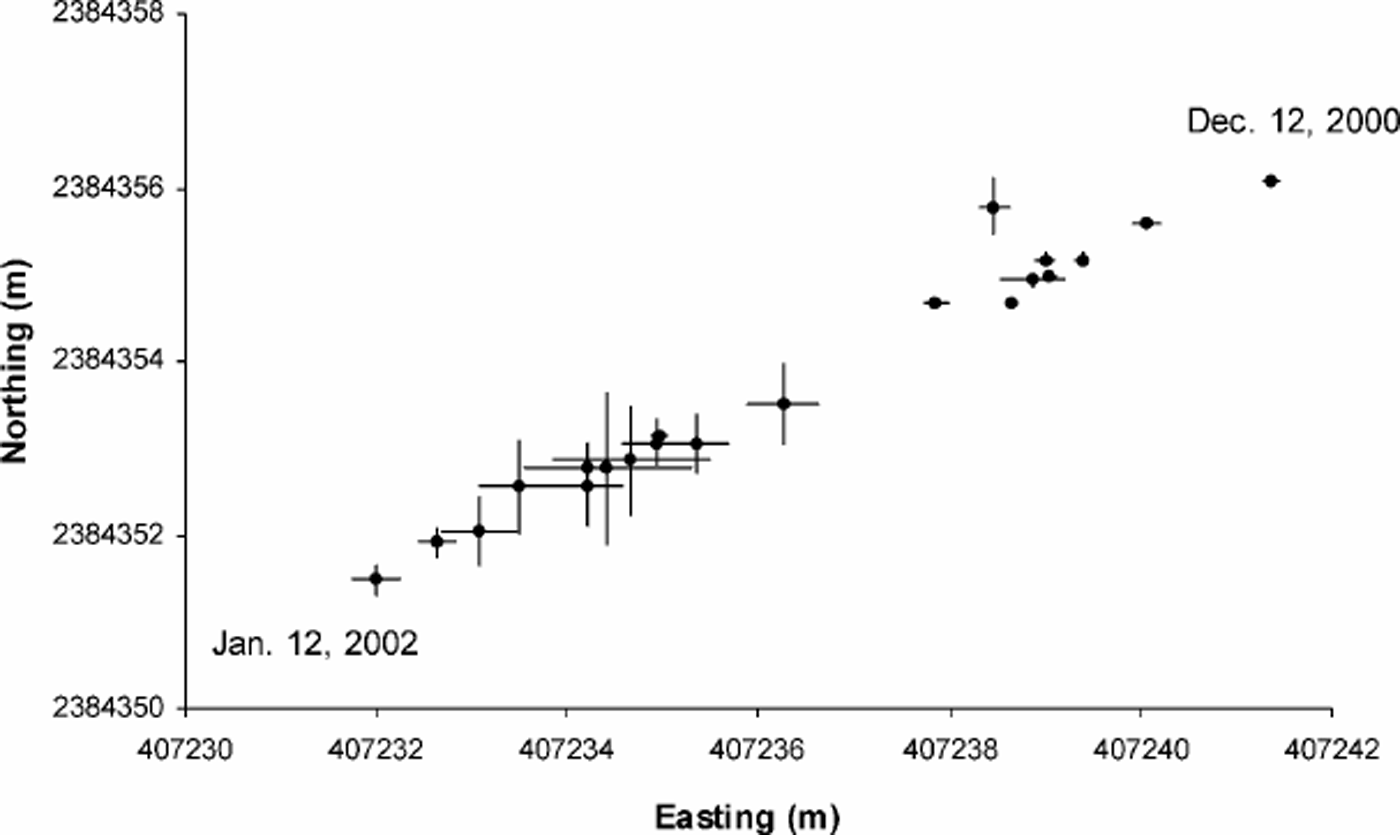
Fig. 10. Plot of DORIS-derived coordinates (UTM (GRS80), zone 44) during the period 12 December 2001 to 12 January coordinates migrate towards the southwest in a regular fashion, reflecting the movement of ice at this location.
Note: The differences in initial coordinates (12 December 2001) may be due to the observations being made at different times of the day.
The DORIS antenna on Sørsdal Glacier was surveyed using static GPS at the time of deployment and again when the installation was retrieved. The ice-flow rates computed using DORIS-derived coordinates (34 cm d–1) are in close agreement with those computed using the GPS coordinates (31cm d–1) as shown in Table 4. The GPS-derived velocities are based on two independent measurements taken 65 days apart, whereas the DORIS-derived velocity is the mean of 30 days continuous data. The 3 cm d–1 discrepancy is due to the differences in survey time between the two methods and the survey precision. The discrepancy of 3 cm d–1 should therefore not be extrapolated as a 9 m a–1 difference in velocity.
Summary
Measurements of ice flow along the northern margin of S⊘rsdal Glacier correlate well with the brittle and ductile structures observed in these regions. At two separate study sites, crevasses were observed to initiate where there is a marked increase in velocity (from approximately 3 ma–1 to 17 ma–1), and continue to show a gradual increase in size, quantity and distortion that correlated with the exponentially increasing velocity gradient through zones of simple shear. This change in velocity gradient is believed to approximate the shear zone boundary as faster-flowing ice of Sørsdal Glacier converges with slow-moving ice of the Antarctic plateau to the north. The geometries of the arcuate and sigmoidal crevasse traces and sigmoidal crevasses indicate a dextral shear sense, which is confirmed by the survey results and is in accordance with fast-moving ice in the south (flowing southwest) juxtaposed with slow-moving ice in the north. The enhanced attenuation of the complex crevasse-trace patterns (products of cumulative deformation), and the increase in crevasse size and frequency also reflect the intensity of the incrementally increasing strain (evident from the changing velocity gradient) from north to south across the glacier margin.
The active fractures in this region strike consistently at 300–330° and have been observed to anneal with meltwater over a single summer season to form the most recent crevasse traces. Observations suggest that most crevasses anneal before they have dextrally rotated >20°. The relative ages of the traces, determined using principles of superposition (e.g. offset criteria), show that the traces continue to rotate and distort until they are sub-parallel to the direction of glacier flow and normal to the direction of principal compression. Where strain rates have been computed, extension is found to be approximately 15% greater than compression (Fig. 9), in accordance with an extensional flow regime indicated by the widespread occurrence of crevassing perpendicular to glacier flow.
The density of crevasses and crevasse traces does not appear to increase downstream along the margin, as observations made at the RFD strain grid are almost identical to those of the CTSN strain grid, which is 10 km upstream. This suggests that clear blue ice from the northern periphery is entering the Sørsdal ice stream at each strain-grid location, and then deforming in a similar fashion while progressing southwest into the central ice stream. Otherwise the crevasse-trace pattern at the RFD strain grid (downstream) would be extraordinarily complex compared to the CTSN strain grid (upstream), and this is not observed. However, the crevasse-trace pattern appears more complex at each location towards the south, farther into the shear zones.
Acknowledgements
The authors would like to acknowledge the support of P. A. Collier and the Department of Geomatics, The University of Melbourne, for providing all of the necessary survey equipment and for helpful advice regarding deformation monitoring and survey networks. Thanks to J. Dawson and R. Govind, of the Space Geodesy Centre at the National Mapping Division of Geosciences Australia, for coordinating the DORIS component of this project. The French space agency (Centre National d’Etudes Spatiales) and the French national survey agency (Institut Geographique National) are thanked for making DORIS available to this project. The support of the ANARE expeditioners of Davis station from 2000 to 2002 is also gratefully acknowledged. This work is supported by an Australian Antarctic Science Advisory Council grant to project 1205, and B.A.P. acknowledges an Australian Antarctic Science scholarship. We thank an anonymous reviewer and D. A. Meese for their comments that substantially improved the manuscript.


