


Introduction
It is a well-known fact that the demand for wireless data is constantly growing at an exponential rate. A look at the evolution of maximum available data rates presented in [Reference Fettweis and Alamouti1] shows that the trend for increased rates has been following the same exponential increase as Moore's Law for semiconductors. Already in 5G data rates exceeding 10 Gbps are expected [2]. This alone pushes the limits of current networks not to mention the very important challenges of network latency and energy efficiency. It is already clear, that 5G technologies with frequencies up to 86 GHz [3] although revolutionary will not be able to support the continuously increasing demand for high data rate. This is why research on the field of millimeterwave wireless communication has been very intense in the last two decades, investigating new paradigms for achieving the ambitious goal of 100 Gbps. Efforts made toward a new standard IEEE 802.15.3d show the potential of the subterahertz frequency band as a possible candidate to support ultra-broadband applications [4]. This standard allocates the frequency band from 252 to 325 GHz to future wireless communication networks, such as backhauling, fronthauling, last-mile access, ad-hoc networks for big events or in dense urban areas, smart offices, and data centers, and is the worldwide first wireless communication standard operating at 300 GHz. Furthermore, eight different channel bandwidths between 2.16 and 69.12 GHz are defined.
The results of all the resources invested toward the goal of 100 Gbps can already be seen. An experiment reported lately in [Reference Castro, Nellen, Elschner, Sackey, Emmerich, Merkle, Globisch, de Felipe and Schubert5] has even outreached this limit. A data rate of 128 Gbps was successfully transmitted over half a meter using a 16-quadrature amplitude modulation (QAM) at a carrier frequency of 300 GHz. The frontend consists of a positive-intrinsic-negative photodiode (PIN-PD)-based transmitter and an active electronic receiver based on InGaAs metamorphic high electron transistors (mHEMT). In total, 100 Gbps were also successfully transmitted using an all-electronic link based on InP HEMTs, like presented in [Reference Hamada, Fujimura, Abdo, Okada, Song, Sugiyama, Matsuzaki and Nosaka6]. Here the center frequency was 300 GHz and the transmission distance 2.22 m. This data rate goal was achieved also by a frontend based on Si technologies. Rodríguez-Vázquez et al. [Reference Rodríguez-Vázquez, Grzyb, Heinemann and Pfeiffer7] present a set of modules in 0.13 μm SiGe HBT technology. Using these components, data rates up to 100 Gbps over 1 m modulated with 16-QAM can be transmitted.
A very promising technology for terahertz communication is the 40nm Si-based CMOS process. Lee et al. [Reference Lee, Dong, Yoshida, Amakawa, Hara, Kasamatsu, Sato and Fujishima8] report on a transceiver based on this technology which achieves a data rate of 80 Gbps over 3 cm at a center frequency of 265 GHz using 16QAM modulation.
All these successful transmissions make 100 Gbps a reality in laboratory conditions. The integration of these links into either a network or other devices demands even more research and poses challenges that were not addressed before. This paper concentrates on the proof of concept for a 300 GHz link for future wireless transport links. This solution will provide the required capacity for backhauling/fronthauling in beyond 5G networks. The work presented here is compatible with the new frequency standard IEEE 802.15.3d
The superheterodyne concept
There are several architectures established for data transmission systems to convert the baseband frequency to the radio frequency (RF) and back. Figure 1 shows the schematic of two concepts for a double-sideband (DSB) transmission, where the modulated sidebands are symmetrically arranged around the used carrier frequency, creating an upper sideband (USB) and a lower sideband (LSB) and resulting in a bandwidth of twice the baseband bandwidth. The single-sideband transmission was for a long time the preferred transmission scheme due to a better performance in fading and multi-path environments, a better receiver performance, but also due to the savings in RF spectrum. On the downside, it requires a more complex filtering or mixer architecture. Since in the terahertz range, spectrum is not an issue, DSB transmission is preferred thanks to a lower complexity.
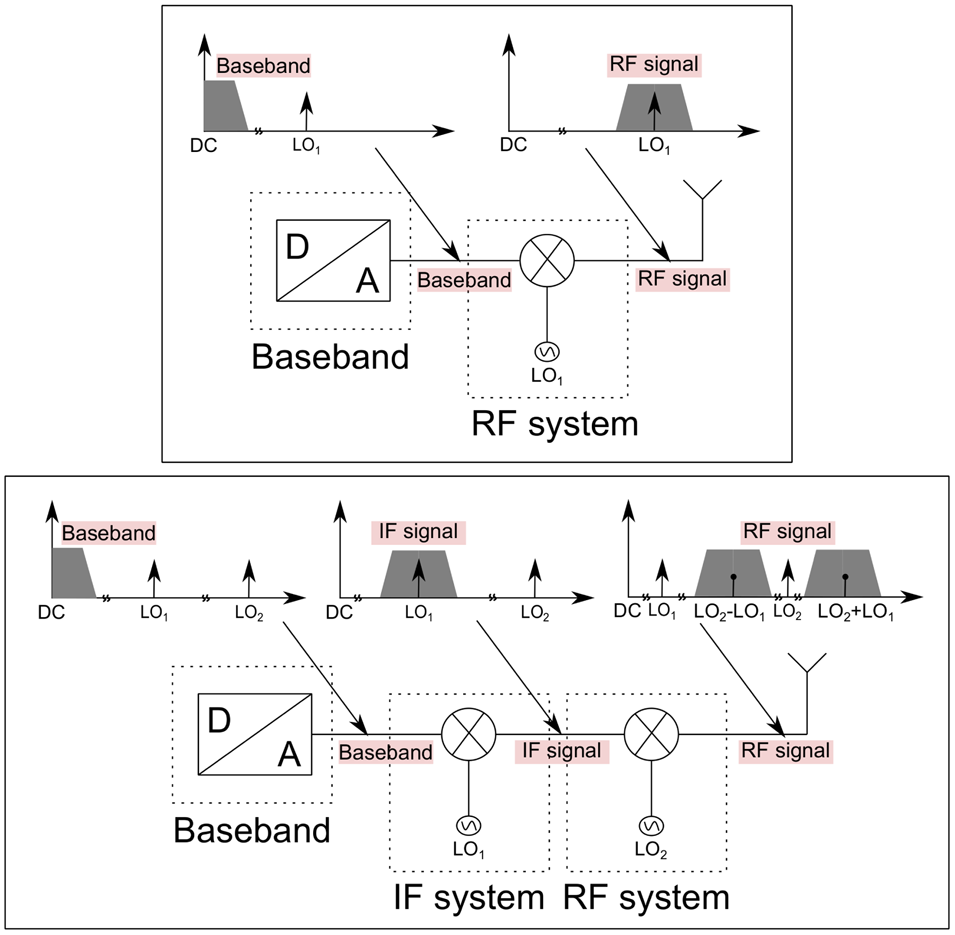
Fig. 1. Simplified schematic of a double-sideband transmission in a zero-intermediate frequency (IF) system (upper schematic) and in a superheterodyne system (bottom schematic).
The first architecture is based on the direct conversion scheme, also called zero-IF, and has been largely used until now for terahertz communication systems. In this case, the converting mixer is used as a modulator, resulting in an RF signal symmetrically arranged around the carrier frequency. From the receiver perspective, the input RF signal is directly down-converted to the baseband, which translates to an IF of 0 Hz, where the information included in the signal can be recovered.
The second architecture is based on the superheterodyne concept and is very common at lower frequencies, but was never used before in combination with IF frequencies above a couple of GHz. In a superheterodyne system, a modulator is used to modulate an IF LO1 with the information carrying signal coming from the baseband. The resulting IF signal is then fed into a second mixing stage, up-converting the signal to the conveying RF range by mixing it with a carrier signal LO2. At lower frequencies, since the gap between the USB and LSB is low, a series of highly selective filters are necessary to suppress unwanted image signals in the RF spectrum. This is not the case at frequencies in the millimeterwave range, where the gap between the center frequencies of the two sidebands is intrinsically high.
The first option has been the architecture of choice used in wireless point-to-point links with carrier frequencies above 200 GHz due to a reduced complexity and component count. Another advantage is that the phase noise of only one instead of two LOs contributes to the total noise of the transmitted signal. High data rates were achieved thanks to the availability of appropriate analog-to-digital (ADC) and digital-to-analog (DAC) converters. These components realize the carrier recovery as well as the clock and data recovery in the digital domain, which means that an enormous computational power to process the bandwidths and data rate is necessary.
But what was once an enabler of wireless ultra-high data rate links and a big advantage of the zero-IF transmission scheme becomes a concern for the integration into a real network. The ADCs and DACs are too expensive and bulky to be used in an application outside the laboratory. Other disadvantages of direct-conversion are the intrinsic sensitivity to direct current (DC)-offsets and an insufficient LO-to-RF isolation. These problems have been investigated in detail in [Reference Dan, Grötsch, Shiba and Kallfass9] and can be avoided in a superheterodyne architecture.
Furthermore, with the significant progress of 5G technologies, the availability of an IF system does not represent a problem anymore, but a chance. Wireless links based on the IEEE 802.15.3e-2017 [4] and on the ETSI EN 302 217 standard [10] are already commercially available in the V- and E-band. Using these components as IF system for a 300 GHz superheterodyne wireless transport link would enable a feasible solution for front- and back-haul in future networks. Figure 2 shows a possible combination of 5G technologies and terahertz communication links integrated in a live network. The last portion of a communication network, which makes the link between an edge cell and the core network, is realized at the moment by either wired or wireless links. The wired solutions are fast but very expensive and often impossible to deploy in remote areas. The future exponential growth of individual data rates means that the access cells have to be smaller and appear more frequent. The increasing number of cells will cause additional costs of optical fiber, which is already extremely high in an urban environment. Employing the solution pictured in Fig. 2 would provide the required capacity for this application but requires a super-heterodyne architecture and can not be realized with already available RF frontends like presented in [Reference Hamada, Fujimura, Abdo, Okada, Song, Sugiyama, Matsuzaki and Nosaka6–Reference Lee, Dong, Yoshida, Amakawa, Hara, Kasamatsu, Sato and Fujishima8].
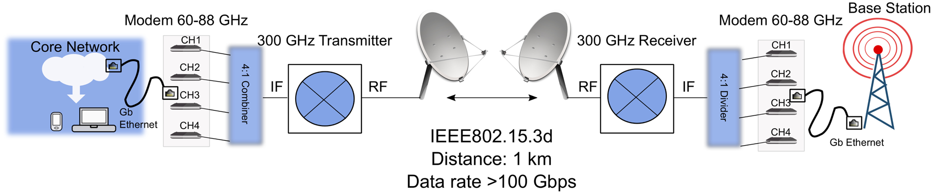
Fig. 2. Proposed solution for the integration in a live network of a 300 GHz wireless link.
The usage of a superheterodyne system like proposed in Fig. 2 involves the parallelization of different IF channels. Combined in the RF, this leads to a high data rate, needed for this kind of application. According to the new 300 GHz standard, the bandwidth of each channel is 2.16 GHz, or a multiple of 2.16 GHz. Due to the relatively low bandwidth complex modulation, formats are a must for high data rates. To sum up, following requirements can be defined for a 300 GHz transmitter and receiver that can be employed in a superheterodyne system:
(1) an IF frequency range between 60 and 86 GHz
(2) an RF frequency range between 285 and 315 GHz
(3) minimum linearity requirements: 64QAM, under channel aggregation
Furthermore, a spectral pure LO source is desired for a good performance of the link.
Since no frontend that achieves the above mentioned specifications is available yet, this paper focuses on the proof of concept for the superheterodyne transmission in the 300 GHz range. For this purpose, an existing RF frontend is used. This frontend has been designed for zero-IF transmission and shows good performance in this range [Reference Kallfass, Dan, Rey, Harati, Antes, Tessmann, Wagner, Kuri, Weber, Massler, Leuther, Merkle and Kürner11]. Two possibilities of realizing the superheterodyne architecture are analyzed. The usage of an arbitrary waveform generator (AWG) which provides the IF by applying a carrier offset to the desired data, validates the concept and the potential of the system. The second possibility uses commercially available mixers, which work as direct up- and down-converters, to generate the IF input and output for the 300 GHz transmitter and receiver. The second option, although realized with far from ideal components, shows the compatibility of the 300 GHz RF system to low-cost IF and models better the application case portrayed above. Key impairments of data transmissions, like linearity and phase noise, are depicted and described in detail.
System analysis
A superheterodyne link like proposed in Fig. 1 can be partitioned in three important components: the RF system, the IF system, and the baseband.
RF system
The RF system consists of a 300 GHz transmitter and receiver based on monolithic millimeterwave integrated circuit (MMIC) packaged in split-block waveguide modules with a WR-3 output at the RF port and a WR-12 at the LO input. The MMICs have been described in detail in [Reference Kallfass, Harati, Dan, Antes, Boes, Rey, Merkle, Wagner, Massler, Tessmann and Leuther12] and are fabricated in a 35nm metamorphic high electron mobility transistor (mHEMT) InGaAs technology with a maximum oscillation frequency above 1 THz and a maximum transit frequency of above 500 GHz [Reference Leuther, Tessmann, Massler, Losch, Schlechtweg, Mikulla and Ambacher13]. Figure 3 shows the schematic of the active electronic transmitter and receiver MMICs.

Fig. 3. Schematic of the active electronic transmitter and receiver MMIC. The two components integrate a frequency multiplier by three, a buffer amplifier, a fundamental passive I/Q mixer, and a final amplifier for the transmitter and a low noise amplifier for the receiver. The MMICs are packaged in a waveguide split-block module.
The transmitter consists of a frequency multiplier by three, a buffer amplifier, a fundamental up-converter, and a power amplifier as a final stage. It achieves a saturated output power of − 5 dBm and 20 GHz of IF bandwidth. The receiver integrates a low-noise amplifier, a down-converter and the same LO path as the transmitter. The receiver module achieves an average conversion gain of 6.5 dB, has an RF frequency of operation between 270 and 325 GHz, and an average noise figure of 8.6 dB [Reference Tessmann, Leuther, Wagner, Massler, Kuri, Stulz, Zink, Riessle and Merkle14].
A very important aspect is the 100 GHz LO input signal. This is generated by a separate waveguide multiplier module with a multiplication factor of 12.
It was shown in [Reference Antes and Kallfass15] that the LO noise floor is one of the most critical parameters influencing the quality of data transmission. Especially, for communication links where wide band signals are transmitted, the phase noise floor at high offset frequencies from the carrier, also known as white LO noise, shows a much more significant impact on the system's performance than the effects introduced by the near carrier phase noise. In [Reference Chen, Kuylenstierna, Gunnarsson, He, Eriksson, Swahn and Zirath16] a new model of LO noise is presented, which defines the white LO noise as being the combination of phase (angular phase error) and amplitude noise. This is of importance, because the signal-to-noise-ratio (SNR) of a frequency-converted signal degrades with increasing LO noise floor.
The LO source for the 300 GHz transmitter and receiver is provided by a commercially available signal source, an Agilent N5183B MXG, at 8.33 GHz. Figure 4 shows the measurement of the LO phase noise at the input of the multiplier module. Phase noise measurements are difficult to perform at the frequencies used at the input of the RF transmitter and receiver. Since no matching measurement equipment was available, the LO phase noise is calculated by adding of 20log(n), where n is the multiplication factor, in this case 12. According to [Reference Weber, Tessmann, Zink, Kuri, Kallfass, Stulz, Riessle, Massler, Maier, Leuther and Schlechtweg17], which presents the phase noise curve of a similar multiplier by 12 module realized using the same technology, the difference between the measured value and the theoretical one is very small in the range of 2 dB. A theoretical calculated phase noise curve of the 300 GHz LO signal is also plotted in Fig. 4. When assuming, that the amount of spectrum which is disturbed by the near carrier phase noise, commonly ranging up to a 10 MHz, is negligibly small compared to the overall modulation bandwidth in the range of several GHz, a white LO noise floor of around − 100 dBc/Hz can be taken into account. As predicted in [Reference Antes and Kallfass15], the influence of the carrier phase noise is expected to be significant. Thus, it would be desirable to generate the carrier signal in a different way. One solution would be to use a signal generated by an optical source. This topic will be discussed in more detail in section “Influence of the frequency source”.

Fig. 4. Phase-noise of the measured LO source at 8.33 GHz and of the theoretical calculated LO input at 100 and at 300 GHz.
IF system
Two possibilities of realizing the IF system are employed. The first uses the option available in the AWG of generating an IF signal centered around a certain carrier frequency. The 10 GHz is most appropriate as carrier frequency to take advantage of the full analog bandwidth of the AWG of 20 GHz. The RF signal contains both side bands, since no filtering is applied. Like shown in Fig. 5, the USB is centered around 310 GHz and the LSB around 290 GHz. The gap between the sidebands determines another limit for the maximum transmission bandwidth, which is 20 GHz. For higher transmission bandwidths, the AWG analog limit is exceeded and an overlap between the USB and LSB occurs. Both facts will lead to a significant degradation of the transmission quality.

Fig. 5. Overview of IF and RF spectra for the two possibilities of realizing the superheterodyne system: using the AWG on the left and the X-band mixers on the right.
The second IF system involves the usage of commercially available mixers, which work as direct up- and down-converters, to generate the IF input and output. They have an IF frequency of operation between 7.5 and 20 GHz with a baseband frequency range up to 7.5 GHz [18]. Although this range covers the frequency bands X, Ku, and K, they will be, for simplicity, referred to as X-band mixers. For an LO frequency of 10 GHz, the resulting IF signal will have a bandwidth up to 14 GHz. Figure 5 shows the IF and RF spectra for this second IF system. The bandwidth limitation of the mixers leads to a frequency gap of 6 GHz between USB and LSB.
Baseband
The transmitted signal is generated by an AWG with 8 bit resolution, 20 GHz analog bandwidth per channel and a maximum sampling rate of 65 GSa/s. The complex in-phase and quadrature (I/Q) data signal is numerically generated as follows: a pseudo random binary sequences with a length of 215 − 1 is converted to an integer sequence and mapped over a QAM constellation. The resulting complex sequence is up-sampled to match the AWG sampling rate range and filtered using a raised-cosine digital filter with different roll-off factors α. In comparison to rectangular pulses, which have a theoretically infinitely broadband spectrum and will influence other frequency bands, raised cosine pulse shaping offers a low adjacent channel interference. The bandwidth (BW) of a broadband signal transmitted in a DSB transmission can be calculated using the following equation:

where R s is the symbol rate.
At the receiver side, a real-time oscilloscope with 60 GSa/s, an analog bandwidth of 20 GHz and 8 bit vertical resolution captures the I- and Q-signals from the receiver, in recordings with a length of 500 μs. A vector signal analyzer software analyzes the incoming signal, subdivided in 2000 packages, each containing 4096 symbols and performs the carrier recovery and the frequency equalization to compensate for the frequency and phase drift along the link. The digital equalization tool of the software has been applied to all the results shown in this paper.
The performance of the link is analyzed in terms of measured root mean square error vector magnitude (EVM). This figure of merit has been chosen at the detriment of bit error rate (BER). BER can be measured using bit error testers, which can generate, transmit, and receive digital signals and compare the received signal with the transmitted ones to identify errors. The disadvantage of such equipment is its inability to perform carrier recovery in an incoherent system. This is only possible when the transmitter and receiver share the same LO signal. Furthermore, BER provides only limited insight into the origin of signal distortions causing the errors. Amplitude and phase imbalances, DC offset, phase noise have a particular signature in the constellation diagram and are reflected in the measured EVM [Reference Georgiadis19].
In the literature, many works can be found that investigate a dependency between EVM and BER. A certain probability of error, P b and accordingly a certain BER can be associated with the ratio of bit energy to noise power density, which is dependent on the SNR. This dependency also takes into account the used modulation format and digital filter [20, Reference Shaik, Rahman and Islam21]. In [Reference Chang, Onohara and Mizuochi22] it is shown that forward error correction codes can be further applied to reduce the BER limit, hence the limit for successful transmission is BER < 4 · 10−3. With the above mentioned dependency between BER and EVM, this translates into an EVM smaller than the following values under the assumption of an Additive White Gaussian Noise channel (AWGN): for QPSK ${26.5}{\percnt }$ , for 16QAM ${15.2}{\percnt }$
 , and for 64QAM ${6.8}{\percnt }$
 .
.
Linearity considerations
Linearity is a key issue in the success of ultra-fast wireless links in the low terahertz range. In the following section, this will be examined for both RF and IF systems.
RF frontend
The 300 GHz transmitter and receiver system presented in the previous section are measured in a scenario they were designed for, when the baseband is directly up- and down-converted in and from the RF range.
The transmitter module is characterized by measuring the power at the RF output using a VDI Erickson PM5B power meter. An LO input power of 0 dBm at the frequency multiplier input is sufficient to drive the up-converter in saturation. Different signals are fed at the IF input using the AWG and the IF power is swept.
Figure 6 shows the measurement results of the transmitter output power. The maximum and minimum input powers are determined by the limits of the AWG. However, the range between − 19 and − 2 dBm is sufficient to determine the linear region of the transmitter. The power meter calculates the results of this measurement by integrating over the whole spectrum. A WR-3 waveguide is used with a recommended frequency range between 220 and 335 GHz. No prediction about possible adjacent channels resulting from undesired mixing products can be gained from this measurement. It cannot be clearly stated, alone from this measurement, that the achieved transmitted power is only in the frequency band of interest, centered around 300 GHz, and with different bandwidths. Unfortunately, no spectrum analyzer capable of measuring in the 300 GHz band was available. Therefore, a theoretical consideration is needed.

Fig. 6. Measured transmitter output power in dependency of the IF input power for QPSK (upper graph) and 16QAM (lower graph) modulation formats and different symbol rates.
Table 1 shows the desired LO carrier and possible LO harmonics after the multiplier module (multiplication factor of 12) and after the integrated multiplier by three. A similar multiplier module as the one used in this work is presented in [Reference Weber, Tessmann, Zink, Kuri, Kallfass, Stulz, Riessle, Massler, Maier, Leuther and Schlechtweg17]. There it is shown that all harmonics are suppressed with a minimum of 35 dBc, with the lowest suppression measured for the 10th and 14th harmonic (X10 and X14). In addition, the buffer amplifier presented in Fig. 3 acts like a bandpass filter further suppressing all signals outside the band 270–330 GHz. This means that only the harmonics 11, 12, or 13 can reach the up-converter and they show a very good suppression in the multiplier module. Furthermore, thanks to the balanced design of the mixer, a good LO to RF isolation assures that the amplitude of the 300 GHz carrier is well below that of the RF signal. This demonstrates that the power measured and plotted in Fig. 6 is the power level of the desired signal centered around 300 GHz.
Table 1. Desired LO carrier and possible LO harmonics at up-converter input

The first important observation is that the transmitted output power is not only dependent on the input power, as expected, but also on the modulation format and symbol rate. The output power decreases slightly with increasing symbol rate. This effect can be observed for both modulation formats, QPSK and 16QAM, but it is higher for the more simple one, QPSK and is a direct consequence of the RF transmitter's frequency dependency. Like presented in [Reference Kallfass, Dan, Rey, Harati, Antes, Tessmann, Wagner, Kuri, Weber, Massler, Leuther, Merkle and Kürner11], the conversion gain of the TX is not constant over the IF frequency, the 3 dB IF bandwidth of the TX lies at around 10 GHz. With increasing bandwidth, the conversion gain decreases, which leads to a decrease of output power for increasing symbol rates in Fig. 6.
The second important observation concerns the saturated output power, which is higher for QPSK than for 16QAM. A constant difference of 2 dB is noted between the same symbol rate and different modulation formats, like shown in Fig. 7. The measurement is realized with a power meter, hence the resulting values represent the average power. Therefore, this result is in good accordance with the theory presented in [Reference Miller and O'Dea23]. For root raised-cosine filtering with a roll-off factor of 0.35, the difference between the peak-to-average power ratio of QPSK and 16QAM is around 2 dB.

Fig. 7. Comparison between measured output power when the symbol rate of the IF signal is kept constant and the modulation format is being varied.
Finally, it can be concluded that although modulation format and symbol rate have an influence on the transmitted output power, the measured curves follow the same trajectory, which means that the input related 1 dB compression point remains the same. For all measured symbol rates and modulation formats, it lies at − 8 dBm.
Using the 300 GHz transmitter, receiver, and a zero-IF setup, like presented in [Reference Kallfass, Dan, Rey, Harati, Antes, Tessmann, Wagner, Kuri, Weber, Massler, Leuther, Merkle and Kürner11], broadband signals are transmitted over the air. Complex modulation formats up to 32QAM are successfully transmitted up to a symbol rate of 8 GBd. Figure 8 shows the constellation diagram for an 8 GBd 32QAM modulated signal measured in a zero-IF configuration. This proofs that the RF frontend used for the superheterodyne system presented in this paper is highly linear.

Fig. 8. Measured constellation diagram for a 32QAM modulated signal with a symbol rate of 8 GBd measured in a zero-IF configuration.
External mixers and AWG
The X-band mixers, which form one option for the IF system in the final superheterodyne experiment, need to be tested and their linearity needs to be analyzed. Since the IF output lies in the range between 7.5 and 20 GHz, their IF spectrum can be measured more easily than in the case of the RF components. For this purpose, a spectrum analyzer is connected at the IF output of the X-band up-converter. The LO signal is provided by a commercially available synthesizer and has a frequency of 10 GHz and an input power of 5 dBm. At the baseband port, a broadband signal with different modulation formats and symbol rates is applied. Figure 9 shows the measured spectra of two IF signals, both modulated using 16QAM. The one plotted using the solid black line has a symbol rate of 3 GBd and occupies a bandwidth of 4 GHz and the second one plotted using the dashed red line has a symbol rate of 6 GBd and occupies a bandwidth of 8 GHz. The poor isolation of the second LO harmonic at 20 GHz is visible for both measurements. An undesired non-linear mixing product can be observed in the spectrum of the 6 GBd signal in the low frequency range, below 5 GHz.

Fig. 9. Measured spectrum of the IF signal generated with the external X-band mixer. The baseband signal is 16QAM modulated and has symbol rates of 3 and 6 GBd.
To characterize the X-band mixers, a back-to-back transmission measurement is conducted. The IF output of the up-converter mixer is directly connected to the IF input of the down-converter mixer. The LO signal is provided coherently from the same source and it has a frequency of 10 GHz and an input power of 5 dBm. The baseband input signal is generated in the AWG. The output baseband signal is captured by an oscilloscope, like described in section “System analysis – Baseband”. Different modulation formats and symbol rates are transmitted in this back-to-back configuration. The 16QAM is the most complex modulation format which was successfully transmitted using this configuration. Symbol rates up to 9 GBd, corresponding to a transmission bandwidth of around 12 GHz are achieved. This exceeds the baseband bandwidth of the mixer indicated in the datasheet [18]. Efforts to transmit 32QAM show that this modulation format is possible if only the up-converter X-band mixers are used. The resulting IF signal is directly fed to the oscilloscope and demodulated using the signal processing software. In conclusion, the superheterodyne link which uses this IF system is expected to transmit modulation formats up to 16QAM.
To determine the full potential of the superheterodyne concept, the IF signal can be generated in the AWG using an internal carrier frequency. This IF signal has, due to the usage of this equipment, a high spectral purity and can cover bandwidths up to 20 GHz. Figure 10 shows the comparison between the measured IF signals using both IF system options. In dotted blue, the spectrum generated in the AWG, and in solid black, the spectrum at RF output of the X-band mixers is plotted. The baseband signal is in both cases the same using 16QAM modulation and a symbol rate of 3 GBd. A similar input power at the IF of the RF transmitter is crucial for a good and fair comparison between the two IF systems. Hence, the input power at the baseband is chosen in order for the output power of the IF signal to have a similar value. This can be observed in Fig. 10.

Fig. 10. Comparison between measured IF spectrum generated with both available options: with the external mixers and with the AWG. The baseband signal is 16QAM modulated and has a symbol rate of 3 GBd.
When using the AWG, no linearity constraints can be derived from the IF system.
300 GHz superheterodyne transmission
Combining all the previously described components, a wireless data transmission experiment is carried out. Figure 11 shows the schematic of the measurement setup. Two antenna systems are employed depending on the desired transmission distance. For a short range, up to 1 m, two horn antennas each with a gain of 22 dBi are used. In addition, a variable attenuator is placed between the receiver and the antenna. This allows the setting of an optimal input power independent of distance and path loss. To overcome even higher distances and to prove that the system is suitable for indoor applications like smart offices, additional collimating dielectric lenses are added in front of the horn antennas to compensate for the additional free space path loss. The maximum transmission distance is 10 m.

Fig. 11. Setup of the terahertz superheterodyne wireless link composed of the RF system, the X-band mixers representing the IF system and the digital-to-analog and analog-to-digital converters, representing the baseband.
Figure 12 shows the measurement results for a short range distance and for 16QAM modulation. The superheterodyne link using the X-band mixers successfully transmitted this modulation format up to a symbol rate of 6 GBd, which corresponds to a transmission bandwidth of around 8 GHz. This even exceeds the baseband bandwidth of the X-band mixer mentioned in the data sheet by 0.5 GHz. In back-to-back configuration symbol rates up to 9 GBd were possible. This points out that the amplitude and phase imbalances introduced by the RF components degrade the signal, making the demodulation impossible. Furthermore, due to bandwidth limitations in the IF system, the SNR is decreasing leading to an erroneous transmission.

Fig. 12. Comparison of the performance of the wireless superheterodyne system using the AWG and the X-band mixers. The transmitted signals are modulated with 16QAM and the symbol rate is increased up to 15 GBd. The transmission distance is 0.5 m.
Constellation diagrams of the signals that achieved the highest data rate are also plotted in Fig. 12. Using the external mixers, a maximum data rate of 24 Gbps is achieved. This data rate can be significantly increased with a better IF system. This is proven by the 60 Gbps achieved with the AWG. The relatively constant difference between the EVM achieved with the external mixers and the one achieved with the AWG is caused by the different SNR values of the IF signals plotted in Fig. 10. The 10 dB SNR difference observed there leads to an EVM deterioration of around 3%.
As predicted in section “Linearity considerations – External mixers and AWG”, the linearity of the X-band mixers is not sufficient for 32QAM transmission. Hence, no transmission with this modulation format using the superheterodyne link that uses external mixers is possible. Successful transmissions were achieved using the AWG option. Figure 13 shows the measurement results for this complex modulation format and up to a symbol rate of 8 GBd. A high linearity of the RF components is a prerequisite for a superheterodyne system designed for future network integration. The transmission of 32QAM up to a bandwidth of almost 11 GHz, under less then ideal conditions, shows the potential of this concept.

Fig. 13. Performance of the wireless superheterodyne system using the AWG. The transmitted signals are modulated with 32QAM and the symbol rate is increased up to 8 GBd. The transmission distance is 0.5 m.
For the 10 m transmission, the superheterodyne architecture is realized only with the AWG, which generated the IF signal centered around a carrier of 10 GHz.
Prior to the 10 m experiment, measurements in back-to-back configuration with a variable attenuator placed between the 300 GHz transmitter and receiver are conducted. As in the case of the longer distance transmission, the superheterodyne concept is realized using the AWG and an IF centered around 10 GHz. The variable attenuator is set for an optimal RF input power of − 40 dBm into the receiver. The same input power reaches the receiver also in the other two transmission cases: 0.5 and 10 m. Figure 14 shows the measurement results of the 10 m transmission and the comparison to the back-to-back measurement as well as to the short range one.

Fig. 14. Wireless transmission results of the 300 GHz superheterodyne link using the AWG under different transmission distances. The transmitted signals are modulated with 16QAM and the symbol rate is increased up to 15 GBd.
Influence of the frequency source
All of the above-mentioned results were achieved using an electronic LO source at 8.33 GHz. Due to the necessary multiplication factor of 36 and considering the important aspects gained from the work presented in [Reference Antes and Kallfass15] and in [Reference Chen, Kuylenstierna, Gunnarsson, He, Eriksson, Swahn and Zirath16], this method is not considered ideal. The influence of the white LO noise is expected to be significant. One solution would be to use a signal generated by combining two optical signals onto a uni-traveling carrier photo diode so that the differential mixing product is the desired frequency signal. A good trade-off would be to generate an LO in the W-band and keep the last multiplication stage integrated in the RF components, like presented in this work.
Since such an optical test bench was not available for the testing of the superheterodyne link, one initial scheme to generate the photonic LO at 8.33 GHz was tested. It is composed of an electrical signal that drives an optical modulator to generate an amplitude modulation, further detected by a photodiode. Then this signal is amplified to reach the required LO level of the RF transmitter and receiver. Figure 15 shows the comparison between the measured phase noise of the electronic source represented in solid black line and the phase noise of the photonic source represented in dotted red line, both at 8.33 GHz. The white noise floor of the photonic LO source is around 10 dB higher than the electronic one. The phase noise of the 300 GHz carrier is calculated adding a factor of 20log(36) as explained in section “System analysis – RF system” and plotted in the dashed black curve and in dot dash red curve, respectively.

Fig. 15. Comparison between measured phase noise of the electronic and photonic source at 8.33 GHz and calculated phase noise curves at 300 GHz.
Further investigation has shown that not only the phase noise of the photonic LO was different, but also the SNR of the LO carrier. A measurement using a spectrum analyzer has revealed that the SNR of the photonic LO is 40 dB, in comparison to the SNR of the electronic LO which has a value of 60 dB. To have a fair comparison between the two measurements, noise was artificially added to the setup using an electronic LO, until the same SNR value was achieved. For this purpose, pure thermal noise coming from a wideband amplifier without any input was added to the LO signal. An electrical attenuator was placed after the amplified noise to adjust the SNR of the LO signal. The available range is between 30 and 65 dB. Figure 16 shows the comparison between two constellation diagrams both representing 16QAM modulated signals with a symbol rate of 1 GBd. The diagram on the left-hand side was achieved using the photonic LO source and has an EVM of 11.3%, while the diagram on the right achieved an EVM of 8.5% using an electronic LO source. A degradation of more than 2% is caused by phase errors due to a higher white noise floor of the photonic LO source.

Fig. 16. Measured constellation diagrams representing 16QAM modulated signals with a symbol rate of 1 GBd using an electronic LO source on the right and a photonic LO on the left.
Figure 17 shows the evolution of EVM when the SNR of the electronic LO is varied. It is shown in this measurement, that not only the phase noise alone has an significant impact on the performance of a wireless link, but also the SNR of the frequency carrier.

Fig. 17. EVM evolution under degradation of the SNR of the LO. The transmitted signal is modulated using 16QAM and has a symbol rate of 1 GBd.
A possible solution of improving the white noise floor at 300 GHz would be to generate the LO using the photonic test bench at 100 GHz. This would reduce the overall white noise floor by 15 dB in comparison to the noise floor using the electronic LO source and frequency multipliers. This is shown in Fig. 15 in the dotted magenta curve, which is calculated by the addition of the factor 20log(3) to the noise curve of the measured photonic LO.
Two important guidelines for the design of the frequency source for future terahertz links can be derived from this measurement. First of all, the SNR of the LO source has to be taken into account and a value of 60 dB is recommended. Second of all, a photonic source in the W-band is preferred to one at lower frequencies due to the influence of white noise floor on broadband transmissions.
Conclusion
This work reports on a 300 GHz superheterodyne system that reaches a maximum data rate of 60 Gbps and can cover distances up to 10 m. Two possibilities of realizing the superheterodyne architecture are available: with commercial, easily accessible mixers and with an AWG. This paper evaluates the advantages and disadvantages of the superheterodyne transmission concept and presents a possible architecture for the integration of a 300 GHz link in a live network.
Since the transmission of complex modulation formats is of vital importance for ultra-high data rate under channel aggregation, a linearity analysis of the RF and IF components and of the final superheterodyne link is presented.
The influence of phase noise on the quality of the transmission is experimentally examined. For this purpose, a comparison between an electronic source and a photonics-based one is realized. The importance of both white noise floor and SNR of the carrier frequency is demonstrated. For future wireless links operating in the low terahertz range, an LO source in the W-band with a low phase noise is recommended.
The link shows compatibility to low-cost existing baseband solutions and to the new IEEE frequency standard for ultra-fast communication networks. Although a redesign of the 300 GHz transmitter and receiver needs to be made, so that the circuits are particularly designed for superheterodyne configuration with an IF frequency of 70 GHz, this experiment validates the applicability of terahertz communication.
Acknowledgement
This work has received funding from Horizon 2020, the European Union's Framework Programme for Research and Innovation, under grant agreement No. 814523. ThoR has also received funding from the National Institute of Information and Communications Technology in Japan (NICT). We express our gratitude to the colleagues at Fraunhofer Institute of Applied Solid-State Physics for MMIC manufacturing. We also thank the IEMN Nano-Microwave RF/MEMS characterization center and the IEMN-IRCICA Telecom platform facilities.
Supplementary material
To view supplementary material for this article, please visit http://dx.doi.org/10.1017/S1759078720000495.
 Iulia Dan received the B.Sc. and M.Sc. Degree in Electrical Engineering from the University of Stuttgart in 2012 and 2015, respectively. Currently, she is pursuing her Ph.D. as a research assistant with the Institute of Robust Power Semiconductor Systems at the University of Stuttgart, with a focus on 300 GHz transmit-receive systems for ultra-fast communication.
 Guillaume Ducournau obtained the Master degree at Rouen University in 2002, and the Ph.D. degree from Université de Rouen, France on fiber optic communication systems usingDPSK/DQPSK in 2005. He is a full professor at the IEMN (Institute of Electronics, Microelectronics and Nanotechnology)/University of Lille 1 and Polytech'Lille Graduate School, in the THz Photonics group. reviewed He is the leader of the THz wireless communications activity at IEMN using optoelectronic THz photomixers, electronic receivers, THz instrumentation, and mm-wave characterization. He has more than 140 publications in peer-international journals or peer-reviewed conferences proceedings and holds one patent. He coordinates the ANR/DFG TERASONIC project for the use of THz photonics technologies and electrical solid-state technologies for 100 Gbps wireless links. He is also a member of the ThoR project, an EU-Japan funded project for the development of super-heterodyne THz transmission systems using IEEE 802.15.3d standard.
 Shintaro Hisatake received his M.E. and Ph.D. degrees in electrical engineering from Doshisha University, Kyoto, Japan in 2000 and 2003, respectively. From 2003 to 2017, he was an assistant professor at the Graduate School of Engineering Science, Osaka University, Osaka, Japan. Since April 2017, he has been an associate professor at Gifu University, Gifu, Japan, where his major fields of research are generation, manipulation, and detection of millimeter and THz waves and their applications. In 2014, he received The Optics Prize for Excellent Papers 2013 from the Japan Society of Applied Physics, and the Osaka University Presidential Awards for Encouragement (2014, 2015). In 2016, he was awarded the Young Scientists’ Prize of the Commendation for Science and Technology by the Minister of Education, Culture, Sports, Science and Technology, Japan.
 Pascal Szriftgiser received in 1996 the Ph.D. degree (“quantum physics”) from the University Paris VI, Laboratoire Kastler Brossel, Paris (France). He then joined the laboratory PhLAM (Physique des Lasers Atomes et Molécules) as a CNRS Researcher. He is currently a Research Director, the leader of the Cold Atoms group, and deputy director of laboratory PhLAM. His expertise spans from cold atoms physics, quantum chaos, non-linear optics in optical fibers to coherent optical communications. He is a coauthor of 68 publications in peer-reviewed journals.
 Ralf-Peter Braun received his M.S. and Ph.D. degrees in Electrical Engineering from the Technical University Berlin, Germany, in 1985 and 1995, respectively. He has more than 30 years of research and industry experience on optical transmission systems and network architectures. After 14 years of research work at the Heinrich-Hertz-Institute, Berlin, Germany, he joined Deutsche Telekom in 1997. He is engaged in network architecture, technology, service, control, Terahertz communications, test networks, and standardization. He is a member of VDE, ITG, and IEEE802.3 working group.
 Ingmar Kallfass received the Dipl.-Ing. degree in Electrical Engineering from the University of Stuttgart in 2000, and the Dr.-Ing. degree from the University of Ulm in 2005. In 2001, he worked as a visiting researcher at the National University of Ireland, Dublin. In 2002, he joined the Department of Electron Devices and Circuits of University of Ulm as a teaching and research assistant. In 2005, he joined the Fraunhofer Institute for Applied Solid-State Physics. From 2009 to 2012, he was a professor at the Karlsruhe Institute of Technology. Since 2013, he holds the chair for Robust Power Semiconductor Systems at the University of Stuttgart, where his major fields of research are compound semiconductor-based circuits and systems for power and microwave electronics.


 Open access