


1 Introduction
Since the emergence of high-power lasers, the field of laboratory astrophysics has rapidly grown[ Reference Remington, Drake and Ryutov 1 , Reference Takabe and Kuramitsu 2 ]. Currently, laboratory astrophysics experiments are able to replicate complex phenomena that are key to understanding processes such as the formation of stars[ Reference Revet, Khiar, Béard, Bonito, Orlando, Starodubtsev, Ciardi and Fuchs 3 , Reference Burdonov, Yao, Sladkov, Bonito, Chen, Ciardi, Korzhimanov, Soloviev, Starodubtsev, Zemskov, Orlando, Romanova and Fuchs 4 ], the dynamics of planetary interiors[ Reference Koenig, Henry, Huser, Benuzzi-Mounaix, Faral, Martinolli, Lepape, Vinci, Batani, Tomasini, Telaro, Loubeyre, Hall, Celliers, Collins, DaSilva, Cauble, Hicks, Bradley, MacKinnon, Patel, Eggert, Pasley, Willi, Neely, Notley, Danson, Borghesi, Romagnani, Boehly and Lee 5 – Reference Davis, Döppner, Rygg, Fortmann, Divol, Pak, Fletcher, Becker, Holst, Sperling, Redmer, Desjarlais, Celliers, Collins, Landen, Falcone and Glenzer 7 ], the behavior of magnetized plasma flows[ Reference Falize, Loupias, Ravasio, Gregory, Dizière, Koenig, Michaut, Cavet, Barroso, Leidinger, Ribeyre, Breil, Takabe, Sakawa, Kuramitsu, Morita, Woolsey, Nazarov and Pikuz 8 – Reference Albertazzi, Falize, Pelka, Brack, Kroll, Yurchak, Brambrink, Mabey, Ozaki, Pikuz, Van Box Som, Bonnet-Bidaud, Cross, Filippov, Gregori, Kodama, Mouchet, Morita, Sakawa, Drake, Kuranz, Manuel, Li, Tzeferacos, Lamb, Schramm and Koenig 11 ] and the evolution of supernovae[ Reference Woolsey, Ali, Evans, Grundy, Pestehe, Carolan, Conway, Dendy, Helander, McClements, Kirk, Norreys, Notley and Rose 12 – Reference Mabey, Albertazzi, Rigon, Marquès, Palmer, Topp-Mugglestone, Perez-Martin, Kroll, Brack, Cowan, Schramm, Falk, Gregori, Falize and Koenig 15 ]. The initial plasma conditions in the experiment need to be controllable and reproducible in order to draw a comparison between the laboratory setting and the specific aspects of the astrophysical system under investigation. To ensure this, target design and fabrication require careful consideration and ingenuity.
The current standard in this field is to use microfabricated targets specifically built for the characteristics of the experiment[ Reference Klein, Deiniger, Gamboa, Manuel, Satcher, Young, Kuranz, Keiter and Drake 16 – Reference Spindloe, Wyatt, Haddock, East, Cross, Danson, Falize, Foster, Koenig and Gregori 20 ]. While this allows maximum adaptability to the desired geometry, it can also imply some drawbacks: the cost of microfabricating these targets is often higher than it would be if they were machine produced, in addition to the lead time required for their manufacturing, assembly and metrology. Moreover, their design is usually difficult to alter after they have been built. Since the targets have to be ready in advance, the experimental plan cannot be modified during an ongoing campaign, unless backup targets are available. Overall, while microfabrication has the capacity to produce targets that best suit the experiment, it can be desirable to increase the flexibility in the choice of sample materials to allow for changes to the intended experimental plan, and the capacity to alter target designs if flaws are discovered.
In this work, we suggest a complimentary approach to target design: a platform based on reusable modular structures that can improve on some of the points described above. The basic components of a target assembly using this design are a sample carrier, a target body and a target fixture. The samples for irradiation are fixed onto the sample carrier, which is itself attached to a target body that defines the experimental geometry. The body is held in its place inside the experimental chamber by a target fixture. Ideally, the samples would be prefabricated foils or structures available commercially, but the possibility exists to microfabricate samples on top of the carriers. Thus, the platform is not intended as a replacement of microfabricated targets, but rather as an alternative that can combine the specificity of microfabrication techniques with the flexibility, reproducibility and alignment robustness that machined modular components provide.
This platform has several advantages: the replaceable sample carriers allow one to change the sample type quickly, according to the requirements of the experiment, without the need to build entire backup targets, as long as the desired material is procured beforehand. This means that, if all the possible samples of interest for an experiment are readily available, it is possible to try all possible configurations and focus on the ones that yield the best results. The use of different modules that form a complete assembly allows for diverse variant pieces to be used as it is most convenient, and these may be produced in different numbers depending on their rate of use. All the parts are designed using computer-aided design (CAD) software and may be machined using computer numerical control (CNC) devices, which makes producing them more precise, since the manufacturing accuracy is determined by the tolerances of the machines, which can be better than for handmade targets. It also makes the targets more reproducible, bypassing the need for metrology of individual targets. After the initial design phase, the manufacturing of additional pieces is fast and cost-effective, which means target production is scalable to large numbers for parts that do not require additional fabrication, and can be done in a workshop with standard equipment. However, the lead time for the initial design and machining of the parts can be long, which requires this process to be finalized early during planning of a campaign. When the initial parts have been manufactured and tested, it is possible to produce copies or slight variants of the initial design on short notice with the support of a dedicated machinist. Since major redesigns of the assembly design are undesirable and might not be possible within the constraints of an experimental campaign, the use of a test target to ensure the viability of a design or the construction of a 3D representation of the experimental setup using CAD models can be helpful to avoid problems at the start of an experiment. The modular approach implies that the targets require some assembly, which means the initial design requires careful thought so that target replacement can be kept easy and fast, allowing for flexibility in the shot plan, as any available sample can be mounted at any time. An uncomplicated design also enables someone who is not familiar with the assembly to still be able to put it together, which is particularly advantageous for remote experimental campaigns.
The initial design presented was specifically intended for experiments on plasma flows, but we believe its design concept shows potential to be generalized to more setups by altering the present components, or adding new ones. This capacity to adapt the different parts of the assembly also means it is possible to introduce corrections and additions to a prior design, even in the late stages of experimental planning, and to improve upon designs from previous campaigns.
In the first section of this paper, we describe the basic design concept of the target platform and provide some examples of the different models that have already been developed. The second section deals with the specific case of targets for use inside of a pair of Helmholtz-like coils, and the third section showcases some results obtained with these designs of experiments at different facilities.
2 Design concept
The main interaction that has been studied using this target platform is the formation and development of rear-driven plasma flows. In this process, a laser pulse is focused onto the surface of a thin foil sample, which leads to the formation of a plasma flow on the side opposite to the laser irradiation. A simplified view of this interaction is given in Figure 1(a), and a specific example of the design concept, employed in experiments involving counter-propagating plasma flows, is shown in Figure 1(b). The target assembly is composed of the following parts.
-
(1) Sample: the material onto which the driver laser will focus. It can be a commercial or otherwise prefabricated foil, which can be affixed to the sample carrier without requiring a target specialist, but it is also possible to microfabricate the sample on top of the carrier if complex structures or materials are required.

Figure 1 Schematic views of the target assembly: (a) side view of the laser–target interaction; (b) 3D visualization of a target assembly with laser cones.
-
(2) Sample carrier: the sample is attached to this part, which has a hole and a machined cone allowing the laser to be focused on the surface of the sample. Foils or composite samples are attached to the carrier using a vacuum compatible adhesive, ensuring that the sample surface is flat. A specific case that was tested experimentally is that of Crystalbond[ 21 ], a solid adhesive with a low fusion point. To apply it, the carrier is heated over the melting point of Crystalbond using a hot plate with precise temperature control. The adhesive can then be applied to heated part, and the sample is placed immediately afterwards. It rapidly solidifies again and leaves the sample flat, stretched and firmly attached to the carrier. The carrier pieces can easily be reused since any adhesive remaining on them can be melted again when they reheat. In the case of microfabricated samples, it is possible to send just the sample carrier for microfabrication and then directly incorporate those carriers into the assembly during the experimental campaign.
-
(3) Body: this constitutes the base onto which all removable parts are attached, and thus defines the geometry of the experiment. This ensures that the assembly is easy to build up while still being reproducible. It is experiment-specific, since the access for diagnostics is defined by the ports in the target body. Therefore, all necessary alignment markers, exhaust and diagnostic ports, and other features required by the experimental setup, must be present on it. Since this part is critical for the experimental setup, it needs to be designed carefully in advance and ideally tested to confirm it is suitable for the specific experimental setup.
-
(4) Target fixture: its purpose is to mount the assembly in the target positioning system of the experimental chamber. It can be a simple post, or a base, or other system that best suits the specific geometry of the experiment, its diagnostic plan and the alignment of the laser. Alignment markers must be added on as many places of the target as necessary to ensure efficient target and beam alignment, minimizing the downtime between shots and making the laser cool down the main limitation for data acquisition.
-
(5) Additional components: any extra parts that are added to the target body in order to meet specific requirements of the experiment, diagnostics, alignment, etc. This could be shielding for the diagnostics, secondary targets, objects for interaction with the plasma, etc.

The pieces were machined using a Deckel-Maho DMU 50 universal milling machine with a tolerance of $\pm$
0.01 mm. The bodies were made of aluminum of grade 3.3547, while the rest of the parts were of aluminum grade 3.3535, 3.0255, 3.1325, or 3.2315. All these materials performed similarly to one another and can be used interchangeably for manufacturing the assembly components. Lead time for the initial production of the pieces can be estimated as short as two weeks, if a dedicated mechanical workshop is available.
$\pm$
0.01 mm. The bodies were made of aluminum of grade 3.3547, while the rest of the parts were of aluminum grade 3.3535, 3.0255, 3.1325, or 3.2315. All these materials performed similarly to one another and can be used interchangeably for manufacturing the assembly components. Lead time for the initial production of the pieces can be estimated as short as two weeks, if a dedicated mechanical workshop is available.
This approach to target design has been applied in several experiments on rear-driven plasma flows. The specifics of the target assembly have been modified to give it different functionalities tailored to the requirements of each experiment. However, the core concept of the platform is versatile and we believe it can be applied to different systems than the one it was originally devised for, giving it the potential to fit the needs of other experimental configurations.
The design shown in Figure 2(a) is used to study flow collisions with static objects. Additional to the standard components of the assembly, it includes a stainless steel obstacle to stop the propagation of the flow. Several different thicknesses were manufactured, to study collisions at different times, as well as to accommodate for different plasma flow velocities, since heavier flows travel at lower velocities and thus cover shorter distances at a given time. The target fixture in this case is a rail that can be screwed to a base or post. In Figure 2(b), a design for experiments on counter-propagating flows is depicted. It includes two sample carriers facing each other, which are used to generate two flows that collide head-on. In this case, the fixture is a stalk that is mounted to the target positioning system of the chamber. This target is also equipped with an aluminum shield that protects the diagnostics from the self-emission of the plasma and a backlighting target for generating X-rays as a probe, visible in Figure 1(b).

Figure 2 Comparison between variant target assemblies for different experiments on astrophysical flows: (a) design for experiments on flow collisions with static objects; (b) design for experiments on collisions of counter-propagating flows, also depicted in Figure 1(b).
Figure 3 shows an example of such a backlighting target, a vanadium sample used for the generation of X-rays used as a radiography source. This is a microfabricated structure, since it is too complex to be machined or obtained commercially. The backlighting target is built on top of a CNC machined plate, which is then attached to the target body using two screws. The structure consists of a 5 μm thick vanadium foil mounted in a 50 μm thick tantalum pinhole with a 20 μm diameter, over a 2 mm aluminum substrate. It includes a laser-machined circular alignment marker, visible in Figure 3(b), which facilitates the alignment of the backlighter laser.
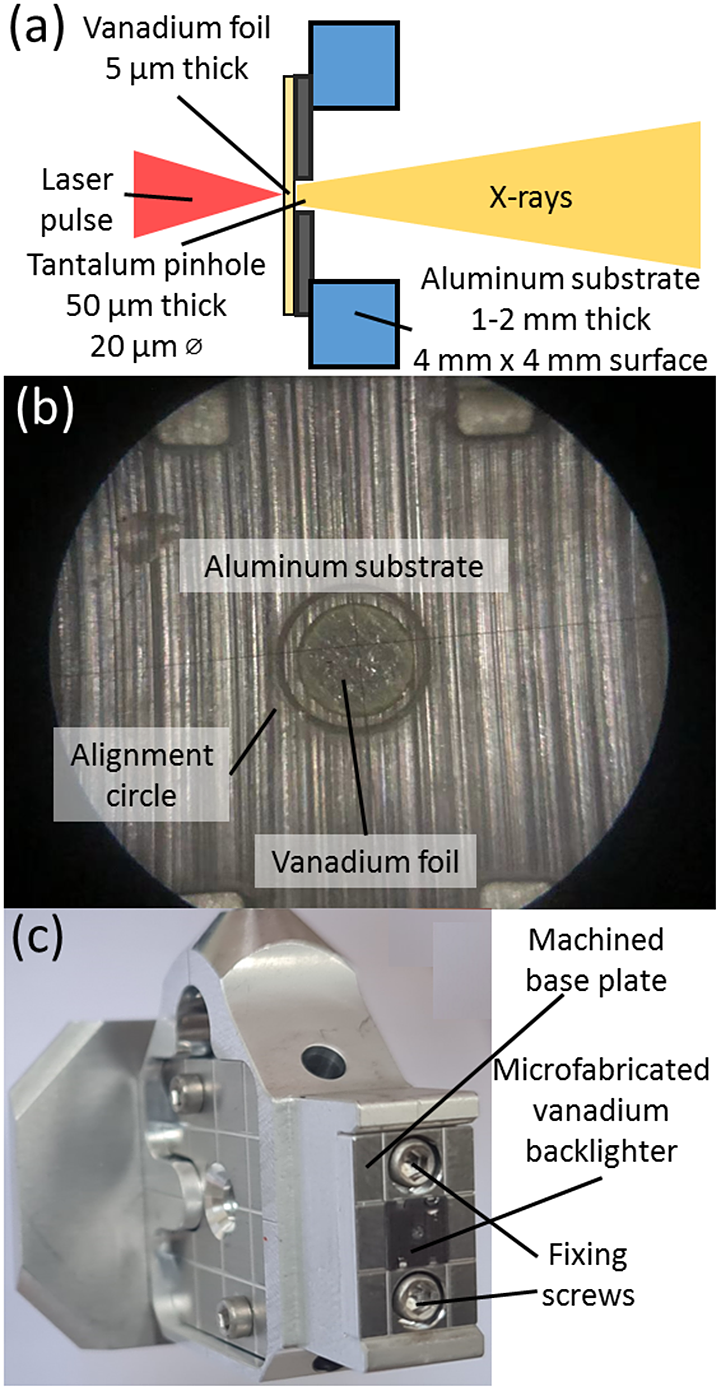
Figure 3 Representations of the microfabricated radiography backlighter: (a) schematic; (b) magnified view; (c) full view of the backlighter plate attached to a target assembly.
3 Incorporation of external magnetic fields
The adaptation of this design to the constrained environment required for generating a magnetic field over the interaction area presents a series of challenges. Numerous design changes are required to accommodate the new physical and mechanical restrictions present in the system, as well as the presence of the additional forces that a strong magnetic field implies. In the setup presented, the magnetic field was generated by a split pair of coils in a Helmholtz-like configuration[ Reference Kroll 22 ]. This means the target needs to fit inside of the coil and align correctly to its center, which imposes a restriction on its geometry.
The basic design concept of the target assembly remains the same, with a carrier where the sample is affixed, which is then integrated into a target body that includes the viewing ports for the diagnostics. In order to place the sample in the correct position inside of the coil, the target body is attached to a rod that brings it to the center of the coil structure. This rod is then fixed onto the side of the coil by a plate with several screws, ensuring its robustness and stability. The structure of the target assembly and the different parts that form it are shown in Figure 4.

Figure 4 Components of a target assembly for use inside a magnetic coil.
To address the concerns related to the effects of the high magnetic field, the assembly was made out of stainless steel of grades 1.4301 and 1.4541, both of which have low magnetic permeability and thus do not react strongly to the magnetic field. Several holes are present to reduce Foucault currents, which can induce deformation of the structure through heating and additional forces.
The complete assembly of the coil target includes a sample carrier, which is screwed inside of a hollow body with several observation windows. On the opposite side to the carrier there is a stainless steel obstacle used to study the collision of a flow with a static object. The position of the sample carrier must be aligned with the starting edge of the observation window on the body, while the obstacle can be placed at any desired distance, using the provided markers as a reference, allowing the study of collisions of flows at any desired stage of development. When both pieces are in position, the body can be fixed by tightening a pair of nuts. The body is then incorporated into the target fixture, where an insertion rod positions the sample in the center of the coils and a plate screws the assembly into the side of the coil housing. A fixing nut made of rigid plastic is added to keep all the components in their place. The final design of the target assembly inserted inside of the coil can be seen in Figure 5.

Figure 5 3D representations of a target assembly inserted into a split pair coil: (a) side view; (b) cross-section. The basic interaction that is studied remains the same as shown in Figure 1(a), with the laser focusing on a thin foil sample and generating a plasma flow in the center of the coils.
Alignment of the target inside of the coil would be challenging, and thus an alternative solution is sought. The use of an external bench with the same geometry as the coil allows one to adjust and pre-align the target outside of the interaction chamber. The assembly of the target, body and obstacle is fixed in the middle of the bench using a screw. The target fixture is then screwed in until the length of the assembly matches that of the bench. When the assembly is at the correct length, it is secured with a rigid plastic nut that keeps the components firmly in place. The setup used to prepare a target for insertion in the coil is shown in Figure 6.

Figure 6 Alignment bench used for alignment of a magnetic field target. The target assembly can be directly taken out of the bench and inserted into the coil, where it would sit at an already aligned position.
4 Experimental results
Results from experimental campaigns on the study of rear-driven plasma flows at two different facilities are presented in this section. Each campaign had its focus on different properties of this system, and thus different diagnostics and experimental setups were used. The design of the target assembly was therefore tailored to the specific requirements of each experiment, proving the versatility of the target platform.
4.1 Campaigns at the SG-II facility
The experimental setup for the experiments at the SG-II facility is shown in Figure 7. The objective of these experiments was to measure the density of colliding plasma plumes by the use of X-ray radiography and flow velocity using streaked optical self-emission[ Reference Albertazzi, Falize, Pelka, Brack, Kroll, Yurchak, Brambrink, Mabey, Ozaki, Pikuz, Van Box Som, Bonnet-Bidaud, Cross, Filippov, Gregori, Kodama, Mouchet, Morita, Sakawa, Drake, Kuranz, Manuel, Li, Tzeferacos, Lamb, Schramm and Koenig 11 ]. For this, the target design shown in Figure 2(b) was employed.

Figure 7 Schematic of the experimental setup for the SG-II campaign. Four beams come from each side, each carrying 250 J of energy, for a total of 1 kJ. The separation between samples is 3.6 mm, and the beams on each side are set to different delays depending on the samples being studied, to ensure the resulting flows meet roughly at the middle of the observation window. The backlighter depicted follows the design shown in Figure 3, and the timing of its driver laser is determined depending on the expected velocity of the plasma flows.
Representative results from the radiography diagnostic can be seen in Figure 8. Some changes were introduced to the initially designed assembly in order to optimize the diagnostic. In an early design, the plasma self-emission from the front and from the trapped material inside the gaps between the sample carriers and the body could get into the field of view of the X-ray diagnostic and contaminate the data, as seen in Figure 8(a). The problems can be solved by using a design where these gaps on the target assembly are filled, and with the introduction of a 2 mm thick aluminum shield, shown in Figure 8(b), which leads to reduced noise in the radiography and makes visible the shock that forms when the two flows collide. This change in shielding requires a small modification of the target body and the fabrication of an extra part, both of which can be done in a short time, but the impact on the quality of the results obtained is significant.
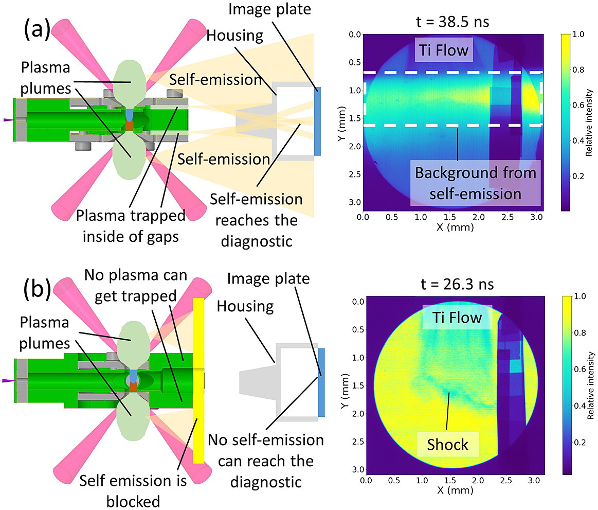
Figure 8 Target changes introduced to optimize the radiography diagnostic at SG-II. Both images show two colliding plasma flows, one formed from a 10 μm titanium foil, coming from the top, and one from a 6 μm polyethylene terephthalate (PET) foil, from the bottom. The latter cannot be seen in the radiography due to the low X-ray absorption of PET. The separation between the samples is 3.6 mm, but the initial 0.3 mm of propagation of each flow is blocked by the target body. In the initial case without shielding, the self-emission of the plasma plume that expands from the interaction area and that of trapped material inside gaps in the target body are able to reach the X-ray diagnostic, projecting a bright stripe into the radiography (a). By adding shielding and eliminating any of the gaps on the assembly, this emission can be blocked and the results are cleaner (b).
The velocity data, an example of which is shown in Figure 9, enables tracking of the expansion of the plasma flow during 3 mm of propagation. The first 0.3 mm behind the sample is shielded by the target body itself, to avoid direct laser light getting into the field of view of the camera. The contamination seen in Figure 8 distorted only the radiographic measurements, while the streaked self-emission remained unaffected due to its different field of view. This diagnostic was intended to accurately measure the velocity of single jets over time, rather than collisions, explaining why only one signal is visible in Figure 9.

Figure 9 Streaked optical self-emission of a single flow from a 10 μm aluminum sample, obtained during the SG-II campaign. The flow velocity can be calculated by tracking the maximum of the detected self-emission over time, and then fitting those points to a line using the least squares method. The flow in the image traverses 900 μm in 12 ns, which corresponds to the velocity of 75 km/s.
The sample carriers proved durable enough to withstand three laser shots before showing any significant damage, and the bodies could withstand at least five shots without deteriorating or deforming to a point that would impair use.
4.2 PALS experimental campaign
The campaign at the PALS facility, the setup of which is outlined in Figure 10, was focused on conducting a wide parametric scan of targets, as well as studying the effects of an external magnetic field on flow formation and structure. Two target designs were used during this campaign, one for studying the propagation of unmagnetized flows, seen in Figure 2(a), and one used to study the influence of magnetic fields, which was discussed at length in Section 3. Both of these designs incorporate the option to place a stainless steel obstacle at an adjustable distance from the sample to study the collision of a flow with a static object.

Figure 10 Schematic of the experimental setup for the PALS campaign.
The ports of the target body allowed one to simultaneously use two diagnostics: streaked optical self-emission, as described in Section 4.1 and shown in Figure 9, and a four-frame interferometry system in a Mach–Zehnder configuration[ Reference Hronová 23 ], the results of which are shown in Figure 11.

Figure 11 Interferometry results for a flow from a 6 um aluminum foil under the conditions detailed in Figure 10 (a) with the target design for unmagnetized flows (Figure 2(a)), and with the magnetic field target (Figure 5) inserted inside the coil with (b) no field, (c) a 5 T field and (d) a 10 T field. All images are taken using a Grasshopper3 U3-28S4 charge-coupled device integrated over 0.3 ns. The limited space and exhaust capacities inside the magnetic field targets cause an accumulation of material visible in the interferograms.
The use of two different target assemblies during the experiment allows one to observe the influence of the target design on the experimental results. Figures 11(a) and 11(b) are images of flows from the same sample, but housed in different assemblies. The results present visible differences despite the identical laser drive conditions used in both images. This shows the target assembly itself slightly alters the dynamics of the flow. The targets for use inside the coil, shown in Figure 4 and with results corresponding to Figures 11(b)–11(d), are narrow and have fewer exhaust ports for the plasma that expands sideways, leading to an accumulation of material that stays confined inside the target assembly that can affect plasma dynamics, and thus the interpretation of the data. In contrast, the targets used for unmagnetized jets, shown in Figure 2(a) and corresponding to the results in Figure 11(a), have more space for sideways expansion and several ports through which excess material can expand and leave the assembly, explaining the differences between Figures 11(a) and 11(b), despite identical drive conditions. Effects such as this mean caution must always be exercised when comparing results obtained using different target designs.
A broad parameter space was explored thanks to the ease of replacement of the target assembly. The targets allow the study of the effect of the magnetic field on the flow, as the visible differences among Figures 11(b)–11(d) show. The sample carriers and bodies for both unmagnetized and magnetized flows were able to withstand three laser shots, and the obstacles for the collisions needed to be replaced after a single use, as they were damaged by the impact of the flow. The rest of the magnetic field assembly presented no visible damage or deformation after 20 shots.
5 Discussion and conclusions
The target platform presented in this paper can reduce the cost and the complexity of manufacturing and assembling targets for laboratory astrophysics experiments thanks to the emphasis on using machined parts. This is in part due to the reduced cost in materials, but mainly because it does not require a target specialist to microfabricate, characterize and assemble the entire target. The component pieces can be manufactured using standard machinery, and the assembly of all the parts can be done by someone who is not deeply familiar with the targets. This also allows for the possibility of remote experiments while maintaining flexibility on the target design.
While this target design does not fully replace microfabrication techniques, it provides an excellent alternative. Moreover, it constitutes a great platform to combine highly specialized microfabricated components, which can be added to the modules, which are robust to align and do not require individual metrology of each target, allowing the flexibility of the modular structure in combination with other target components.
This platform is adaptable, since different components can easily be added to build target variants customized for specific setups. The basic design principle is applicable even in cases with very constrained geometries, as in the case of the insertion of the target assembly inside of a pair of Helmholtz-like coils. The presented platform implies tighter geometrical constraints when compared with traditional microfabricated targets, but it has the benefit of allowing one to iterate and modify existing designs to fit any number of experimental geometries.
The flexibility when choosing the target sample allows for last minute alterations in the shot plan, which means the experiment can be focused on the most promising samples, using the data obtained in prior shots. As a consequence, extensive datasets covering a large parameter space can be built, while also saving costs in redundant targets by only using the samples that provided useful results. This is an improvement over microfabricated targets, which usually require targets to be ready in advance of the campaign, restricting the freedom to course correct after the first results are obtained. When testing the design in different facilities, it has yielded reproducible results, and the need to prepare the target before shooting did not prolong the shot cycle thanks to the ease of assembly and use of the targets. The durability of the individual parts allows for multi-shot capabilities, further reducing the need to manufacture extra pieces.
Through the use of this platform, a number of astrophysical phenomena can be studied in the laboratory at a reduced cost from that usually associated with these experiments. This also opens the possibility for more systematic studies where target conditions are varied slightly in order to obtain better statistics and a more detailed understanding of how the different characteristics of the target material can affect plasma conditions and the subsequent dynamics of the specific astrophysical phenomena being studied.
Acknowledgements
The authors would like to acknowledge the work of the laser teams at the SG-II facility and the PALS facility, as well as the assistance in target manufacturing provided by the HZDR mechanical workshop. Additional funding was provided by the Student Grant Competition of CTU (No. SGS22/180/OHK4/3T/14), the Ministry of Education, Youth & Sports of the Czech Republic (No. LM2018114) and the Horizon 2020 project Laserlab-Europe V (No. 871124). This work was funded by the Helmholtz Association (No. VH-NG-1338).


 Open access