


Locating objects and features in three-dimensional space is a critical component of archaeological field investigations, and the past several decades have seen digital tools gradually replace traditional recording methods (Stephen and Craig Reference Stephen and Craig1984; Dibble Reference Dibble1987). Electronic distance measurement (EDM) devices, or total stations, have generally been archaeologists’ go-to tool for recording three-dimensional coordinates at a range of scales, from artifact proveniences to landscape mapping. However, archaeology has begun to follow the larger survey community in shifting away from EDMs and toward the use of high-precision, survey-grade global navigation satellite systems (GNSS). These systems include the well-known global positioning system (GPS) operated by the United States and satellite navigation systems operated by other countries, such as GLONASS, Galileo, and BeiDou. Most archaeologists are familiar with mapping-grade GPS devices used in field survey. These devices use aspects of the GNSS (called code-based) signals to provide precision that can approach 10 cm–20 cm. In comparison, survey-grade systems use carrier- or phase-based aspects of the signal and, with proper use and some form of correction data, which we will discuss below, can provide high-precision (1 cm–2 cm horizontal and 3 cm–4 cm vertical) coordinates. Survey grade GNSS systems offer key advantages over EDMs because they do not require a clear line of sight between an instrument and reflector (which can pose challenges in areas where vegetation, buildings, or topographic features obstruct visibility) and can map features over long distances. All GNNS systems, however, have two notable limitations. To be most effective, they need a clear sky so that signals from the satellites are not blocked or attenuated by intervening obstacles. As a result, they may have reduced accuracy in forested areas, narrow canyons, or urban areas where there are tall buildings. A second limitation, multipath error, develops when the GNSS receiver is near a radio-reflective surface such as a chain-link fence.
Another limitation survey-grade GNSS instruments have is that to obtain high precision coordinates from one instrument (often designated as an autonomous position), a location needs to be occupied for (typically) more than 20 minutes. However, real-time kinematic (RTK) survey-grade systems provide near instantaneous high-quality coordinates by transmitting correction data from a stationary base station established over a known point to a mobile unit, or rover, enabling the XYZ position of the rover to be calculated within a few centimeters. Survey-grade GNSS systems have been available for more than a decade, but the high cost (often exceeding $20,000 for the two devices needed) and large size of commercial systems has limited the degree to which most archaeologists make use of this technology. Now a new generation of low-cost GNSS receivers is making precise survey data available and applicable to a much wider range of archaeological projects. While these new receivers have some limitations (such as receiving satellite signals on only one frequency rather than the two or more frequencies of more expensive systems), they provide new tools for archaeologists to collect survey data for many research goals, including recording artifact and feature proveniences, laying out site and survey grids, preparing aerial surveys, and constructing topographic maps.
This paper provides an overview of how low-cost GNSS RTK systems can be integrated into archaeological research. While several companies have begun producing such systems, at this point, most offerings are in kit forms and are primarily intended for drone control system integration and similar applications. They also require additional technical skills to be field usable. As a result, we focus here on the Reach RS and recently released RS+, a relatively new, low-cost, single frequency GNSS RTK receiver produced by Emlid Ltd. and designed primarily as a terrestrial survey instrument. It is likely that soon we will see other vendors move into this space.
After reviewing various approaches to set up the instrument for archaeological applications, we discuss results of case studies in which we have deployed this system on field projects, offering both a practical guide to implementing GNSS RTK surveys as well as some cautionary issues for prospective users. We have also provided detailed workflow guides and related information on a website (https://n2t.net/ark:/87296/s6159w) that extends the information provided here.
LOW-COST HARDWARE
Some companies that have released RTK systems based on mass-market, low-cost GNSS chips include offerings from Navspark, Drotek, Swift, and ProficCNC. Most of these products are intended for uses other than terrestrial survey. The Emlid Reach RS is currently the only RTK system priced under $1,000 ($799 per unit) that is sold as a fully functional survey instrument out of the box. The Reach RS comes with a built-in long-range (LoRa) radio, is based on GNSS receiver chips from the Chinese chip maker U-Blox, and runs a variation of the open-source RTK processing software RTKLib (https://github.com/emlid/RTKLIB). It is important to note that two devices are required for a self-contained system that does not depend on remote access to correction data (see below). The base of the receiver has a camera tripod mount (1/4 in) as well as a brass adaptor for a traditional survey tripod mount (5/8 in) so that the device can be mounted on a variety of tripods. Operating a pair of Reach RS units in the field requires a base-station tripod, a 2 m survey pole, a browser-enabled mobile device (a cell phone, an android tablet, or an iPad) or a Bluetooth-capable survey data collector, and a measuring tape. The Reach RS is powered via an internal rechargeable lithium-ion battery. Emlid claims 30 hours of operating time on a full charge, and our fieldwork testing corroborates this. For longer-term operation, the Reach RS can also be powered via the nine-pin connector on the bottom, which we have used in some fieldwork setups.
Applications
The Emlid Reach system provides a number of workflow options depending on the survey type and field conditions. The traditional option is to use a pair of receivers and utilize the built-in long-range radios. In this case, the receivers can operate in RTK mode with one receiver acting as a base station that is set up over a known location and sends real-time correction to the second receiver acting as a rover. In this setup, the rover can record survey points in several ways: 1) internally, using onboard tools built in to the firmware and accessed via any web-browser-enabled device such as a cell phone or tablet; 2) on a traditional survey-data logger, such as the Archer and Mesa models from Juniper Systems (JuniperSys.com); 3) directly on any windows-based tablet or computer running data-logger survey software like SurvPC from Carlson Software (CarlsonSW.com); or 4) on android or iOS tablets running free or low-cost third-party survey apps, such as Mobile Topographer Pro (http://applicality.com/projects/mobile-topographer-pro/ or https://play.google.com/store/apps/details?id=gr.stgrdev.mobiletopographerpro). If the unit operating as a base station is set up over a known previously surveyed point with a high degree of accuracy, the points recorded by the rover should have centimeter accuracy. The data output formats available from the rover will depend on which method is used to collect data. In the simplest method, the onboard firmware tools can be accessed by any web-browser-enabled device, and data can be exported directly in CSV, DXF, GeoJSON, or ESRI shape-file format. However, at the moment, this onboard system will only record data in latitude, longitude, and height (EPSG:4326). Displaying or recording coordinates directly in a projected coordinate system, such as UTM, requires one of the other methods mentioned.
While the availability of known points over which to set up the base station can be a major hurdle for archaeological projects working in remote locations, there are several solutions to this issue. First, the Emlid can establish its own relative base-station position over an unknown point by averaging its uncorrected, estimated location over several minutes. In this situation, the rover can obtain centimeter-accurate coordinates relative to the base station, but the entire survey will float relative to real-world coordinates by the error in the location of the base station, which could be up to several meters. Additionally, if the uncorrected, “averaged” base location is too inaccurate (tens of meters), the relative accuracy can also suffer. However, in many archaeological applications, accurate and repeatable relative measurements are much more critical than real-world, geodetically accurate coordinates, making this a viable option in many instances. In this case, as long as the base station is always set up in the same location and the original averaged coordinates are used for that point, all points recorded with the rover will be accurate relative to each other. Alternatively (for projects in the U.S.), the coordinates for a local base station can be post-processed using automatically recorded log data from the base station combined with data from a local National Geodetic Survey (NGS) continuously operating reference stations (CORS; www.ngs.noaa.gov/CORS/), if available, or other data sources (see below). This process is more technically demanding, and we have prepared a guide that is available on the accompanying website (https://n2t.net/ark:/87296/s6159w). It is also possible to establish base-station coordinates using precise point positioning (PPP; cf. de Bakker and Tiberius Reference de Bakker and Tiberius2017; Zumberge et al Reference Zumberge, Heflin, Jefferson, Watkins and Webb1977) and a log file from a single Reach RS unit. This provides results with accuracy less than the other alternatives but may still be acceptable for many purposes. Finally, coordinates for a base station could instead be established by using a dual-frequency receiver for static GNSS survey in conjunction with the Emlid Reach RTK system. Standard dual-frequency, survey-grade receivers from many vendors can be used as well as lower-cost (~$2,300) static GPS instruments like the IG3s from IGage (igage.com). Such an instrument can be used to establish base-station coordinates for the Emlid system with a minimum of 15 minutes of observation data in much of the United States or two hours of data anywhere. One IG3s and a pair of Reach RS units allow rapid recording of accurate coordinates, even in remote locations, for a low cost. Processing data from a dual-frequency receiver is simplified by using one of a variety of online tools such as the Canadian Spatial Reference System (CSRS) PPP tool provided by the National Resources Canada (NRCAN) Canadian Geodetic Survey (webapp.geod.nrcan.gc.ca/geod/tools-outils/ppp.php?locale=en), the Online Positioning User Service (OPUS) maintained by the NPS (www.ngs.noaa.gov/OPUS/), the Automatic Precise Positioning Service (APPS) maintained by the Jet Propulsion Lab (apps.gdgps.net/apps_uniquefeatures.php), or the GNSS Analysis and Positioning Software (GAPS) maintained by the University of New Brunswick (http://gaps.gge.unb.ca).
Alternatively, if you have access to the internet via a cell phone with data service, it may be possible to operate one Reach RS receiver in RTK mode using a remote correction service. Some states in the United States provide free RTK correction data, such as the Vermont Enhanced CORS and Transmission of Real-Time Corrections (VECTOR) service (http://vector.vermont.gov/trimblepivotweb/). A list of free RTK services is available at http://gpsworld.com/finally-a-list-of-public-rtk-base-stations-in-the-u-s/.
Paid services are available in many parts of the world. In 2017 we utilized the national subscription RTK network in Israel (www.mapigps.co.il/) as part of the Galilee Prehistory Project survey at Tel Nes. In such cases, one Reach RS receiver can receive correction data from a remote base station via a cell phone data hotspot. The baseline length limitations of single-frequency receivers, however, can become significant.
The Reach system also provides a novel approach to recording accurate landscape data. One of the traditional uses of GNSS and EDM survey instruments for archaeology was to record topographic data for building landscape maps around archaeological sites and surveys. These topographic surveys usually require many hours of point-data collection yet result in relatively low-resolution contour maps. Increasingly, mapping sites and landscapes is being accomplished through photogrammetric processing of drone-acquired aerial imagery, which offers collection times that are far shorter while also producing higher-resolution data (Verhoeven Reference Verhoeven2011). In most drone survey workflows, ground control points (GCPs) are laid out over the survey area, their coordinates are recorded using a total-station or GNSS system, and then a drone is flown over the survey area to record the overlapping images necessary for photogrammetric data extraction. GCP data is then combined with the image sets in photogrammetry software packages such as Agisoft Photoscan Pro (Agisoft.com) and Pix4d (Pix4d.com) to produce accurate orthophotographs and digital elevation models (DEMs). As drones have become more powerful, reliable, and affordable, the placement and recording of GCPs is the most time-consuming part of drone survey, while the survey equipment necessary to do so represents the most expensive and bulky component (Roosevelt Reference Roosevelt2014). The Emlid Reach RS can be used to record GCP coordinates quickly and accurately using a system that is low cost and ultra-portable. In some cases, the standard code-based, onboard GPS units in UAVs can be replaced with a code- and phase-based receiver (such as the Reach M+), providing much higher-quality camera positioning for use during photogrammetric processing. Depending on the project objectives, the use of sUAS RTK control may even reduce or eliminate the need for GCPs (Hill 2019).
Finally, since the Reach RS can output its RTK position in the NMEA format that many devices require for precision GPS data integration, the system potentially can be paired with a variety of geophysical instruments to increase survey accuracy and to speed data collection.
Data Collection Workflow
There are several ways to deploy the Reach, depending on survey goals, geographical location, and available hardware. More detailed guides covering setup, operation, and post processing of data collected with the Reach system, as well as a sample dataset, are available at https://n2t.net/ark:/87296/s6159w.
Limitations
Along with the many benefits offered by the Emlid Reach RS, there are some significant limitations. Like other low-cost GNSS devices, it only receives satellite signals on one frequency (L1 - 1575.42 MHz) whereas higher-cost traditional RTK GNSS systems receive satellite signals on two or more frequencies (L1 - 1575.42 Mhz + L2 - 1227.60 MHz). Dual-frequency receivers allow the easy elimination of ionospheric transmission impacts, quickly improving the location accuracy. They also allow longer functional baseline lengths, or the distance between the base station and the rover. Emlid's published specifications for the Reach RS say that the units can function up to 15 km from the base station with accuracies that degrade as distance increases at the rate of 1 mm/km, although in practice the viable distance may be considerably shorter. In addition, it takes more time (often several minutes) for the single-frequency receiver to calculate its initial position and obtain a fixed position after startup.
Similarly, there are limitations on precision GNSS measurements that may not be obvious to users coming from total-station-based recording. For example, while GNSS systems can operate without intervisibility between the base station and the rover, they require continuous communication with a constellation of satellites. Thus, recording can fail for reasons including radio interference between the base station and rover, the number of satellites that are visible above the horizon, orbit errors in the satellites, ionosphere error, troposphere error, and multipath error (Van Sickle Reference Van Sickle2015 covers these issues). Thus, it is important to bear in mind that there are nonobvious reasons it might be difficult or impossible to get accurate data from an RTK system in certain contexts. In places where a total station would work perfectly well, a GNSS system might struggle. For instance, a total station can work in a forested environment if the targeted points are visible from the total station. Conversely, a GNSS system will struggle in forested environments because tree canopies interfere with L1 and L2 signals (e.g., decreased signal-to-noise ratio and increased cycle slips).
As we note in more detail below, a major difference between the Emlid and the much more expensive professional survey-grade devices is that the latter are more successful in the acquisition of high-quality positions in challenging settings, such as in areas that have extensive vegetative cover (e.g., forested areas), steep canyons, or metal structures. While many archaeologists will be happy to simply acquire a location's XYZ coordinates, professional survey instruments are part of a combined software and hardware environment that focuses on professional surveyor objectives that go far beyond simple coordinate acquisition.
Users coming from total-station systems may be unfamiliar with what is often termed the grid-to-ground problem. Coordinates from GNSS systems are usually reported in geographic coordinates (latitude, longitude, and height), while archaeologists are accustomed to working in Cartesian coordinates, often using grid projections like the universal transverse mercator (UTM) or state plane coordinates (SPC). The conversion between geographic and projected coordinates is non-trivial and can create a major source of error (see Limp and Barnes Reference Limp and Barnes2014). Additionally, GNSS systems provide elevation in “ellipsoidal” height (HAE). Standard elevations as shown on traditional maps are “geoid” based (this is the technical term for what is commonly called mean sea-level elevation). The conversion of HAE to the traditional elevation value is a simple mathematical process. As long as traditional elevation values are not needed, using HAE values for the site elevations are more than satisfactory. Finally, all users should be cognizant that because of fundamental issues such as satellite geometry, the precision of any GNSS-derived elevation value commonly will be less than the quality of the horizontal coordinates.
ACCURACY
Low-cost RTK systems like the Emlid Reach RS can provide useable positioning data for archaeological surveys only if they provide sufficient accuracy. To assess the quality of the units, we compared Reach RS–derived position information with position information obtained through a professional dual-frequency RTK system produced by Leica Geosystems: the GS15. By way of comparison, the commercial value of the Leica system can range between $10,000 to $20,000 per unit depending on configurations.Footnote 1 We elected to set up an evaluation that was comparable to real-world archaeological field practices. It is important to understand that the results presented here are not representative of a robust metrology-based assessment but are designed to reflect the likely results archaeologists would generate when using the systems in the field. We have provided the details of the testing regimen on the associated web page.
Using Known Points
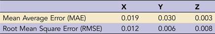
In the main test, we compared results from the Emlid and Leica systems by recording points in an open field (Figure 1) with the base station from each system set up over a known point. In survey parlance, a known point is one for which the mapping coordinates have previously been determined. Finding or establishing a known point may be challenging in real-world archaeological settings (see below), but this test allowed a direct comparison of the relative accuracy of these two systems. We assumed here that the dual-frequency Leica system provides the most accurate results and we compared the difference between points recorded with the Leica and Reach systems using a previously surveyed base-station coordinate. In all tests, any point with a float solution was removed. Essentially, the float solution flag indicates that the quality of the point is substantially reduced from the desired fixed solution. Commonly, this is due to the presence of tree cover or structure proximity. When both the Reach RS base station and rover devices had a clear view of the sky, they provided very good results. Tables 1 and 2 provide the results of two tests of the Reach RS, with 5- and 10-second recordings per point respectively. Both mean average error (MAE) and root mean square error (RMSE) results are presented. We present these in three-dimensional coordinates. As we have noted above, the height value in GNSS is one of the more challenging dimensions to calculate. A rule of thumb is that the vertical dimension often has one to two times greater error than the horizontal dimensions. As can be seen in the 5-second recording, both the MAE and RMSE values are under 4 cm. For the 10-second recording, results are much better. The RMSE value for the X dimension is only 1.2 cm, and the Y and Z values are at the millimeter level.
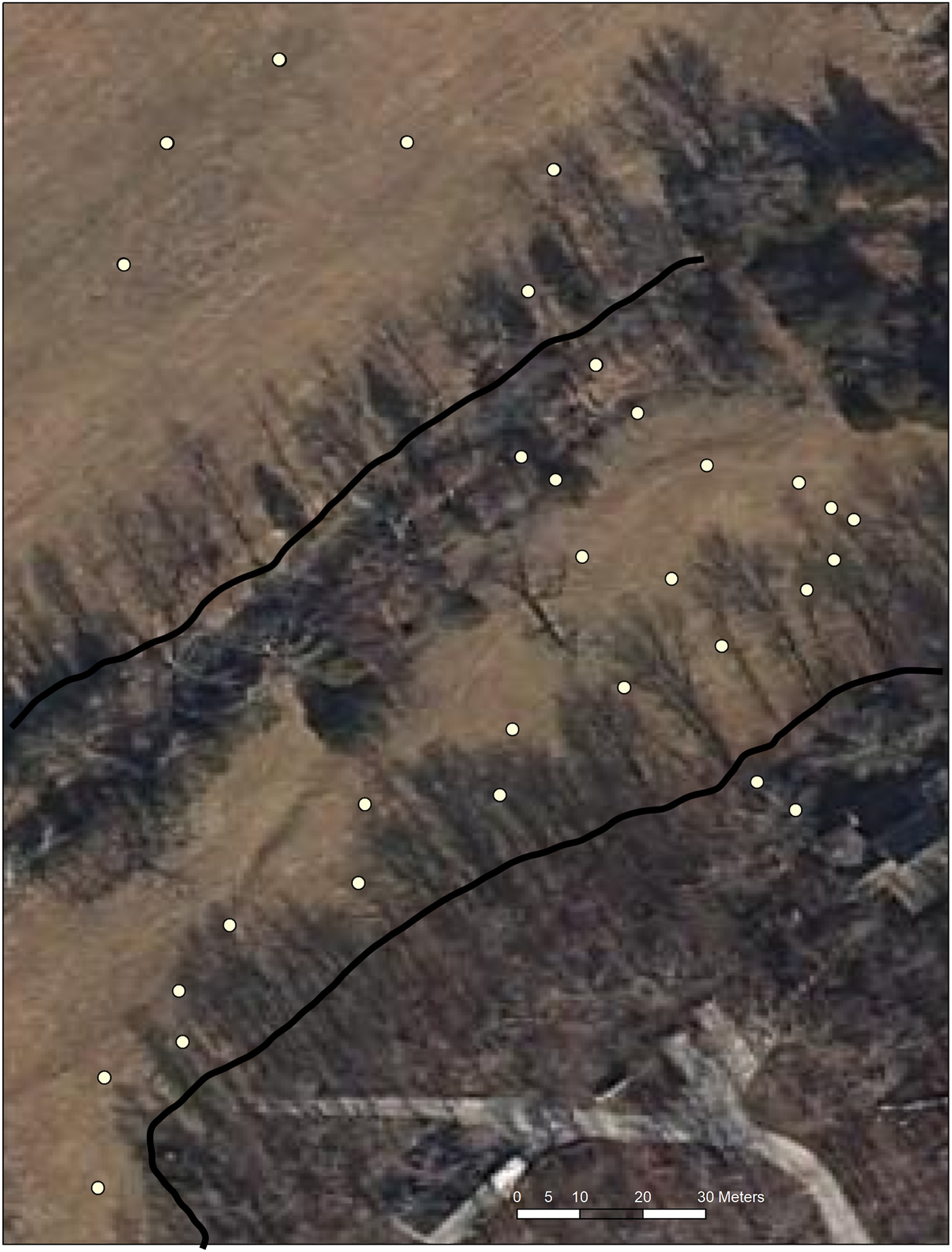
FIGURE 1. Locations of survey points in the test comparing Reach RS and Leica GS15. Each point was recorded by both instruments, and then the computed positions were compared. Note the placement of points in open spaces and near trees.
TABLE 1. Test 1 Comparison of All Leica GS15 to Reach RS Points Using 5-Second Recording for 21 Locations.*

* all float solutions removed. Differences in meters.
TABLE 2. Test 2 Comparison of All Leica GS15 to Reach RS Points Using 10-Second Recording for 20 Locations.*
* Float solutions removed. Differences in meters.
Given that we had duplicate surveys of the same locations, we also compared the results from the Reach RS of both surveys, as shown in Table 3, to examine how replicable the results are. As with the Leica comparisons, all float solutions were removed before the metrics were calculated. RMSE values ranged between 1.6 cm–3.2 cm in X, Y, and Z dimensions. Remembering that the effort was to duplicate standard archaeological practice with brief occupation times, these results are quite good.
TABLE 3. Comparison of Reach RS Test 1 to Reach RS Test 2 Points.*

* Float solutions removed. Differences in meters.
Over Any Point
In the previous comparison, we examined the RTK capabilities of the Reach RS. In that comparison, the initial coordinates of the base-station point were determined using the Leica GS15 system and differential correction processing via the NGS's OPUS. The resulting comparison assessed just the RTK capabilities of the Reach RS in an apples-to-apples comparison. There are many situations, however, when no known point is available. In conventional GNSS survey, this is often referred to as setting up “over any point.” In this approach, extended data is obtained by the base. The position generated by this extended data is then adjusted using other concurrently recorded station data.
There are several free, online systems that, unlike OPUS, accept single-frequency, L1-only data like that recorded by the Reach RS. One widely used system is the National Resources Canada's (NRCAN) PPP service available at webapp.geod.nrcan.gc.ca/geod/tools-outils/ppp.php. The strategy used in PPP is technically very different from that used in OPUS, and it is beyond the scope of this paper to explain the differences. A brief, accessible explanation of PPP can be found at www.novatel.com/an-introduction-to-gnss/chapter-5-resolving-errors/precise-point-positioning-ppp/. Usefully, PPP processing can be obtained for observations made anywhere on Earth without the constraints of baseline length. It has been our experience that the accuracy of L1-only PPP code-based processing may be only marginally better than an uncorrected (e.g., autonomous) base-station position estimate. However, NRCAN upgraded their PPP service on August 16, 2018, to add code and carrier-based processing for L1-only receivers. We submitted both the single-frequency Reach RS and dual-frequency Leica base-station data to the newly updated service and compare the results in Table 4. Differences of only 1.4 cm and 6.8 cm in the X and Y dimensions are impressive, and the significantly bigger 53.7 cm difference in Z is not surprising. This improved agreement between single and dual frequency receivers suggests that PPP processing may be a good alternative for users in remote locations with no nearby CORS data.
TABLE 4. Comparison of Leica GS15 NRCAN PPP Processing to Reach RS NRCAN PPP Processing.*

* The coordinates calculated for the base-station position using both instruments are provided in universal transverse mercator (UTM) coordinates. Differences in meters.
However, if there is nearby (<~100 km) NGS CORS or International GNSS Service (IGS) CORS data available, it is also possible to use the free and open-source, PC-based software RTKLib (www.rtklib.com/) to post-process static data collected with a single Emlid Reach unit to establish a base-station coordinate with a high degree of accuracy (up to centimeter accuracy). We provide detailed workflow for this in the associated webpage. This postprocessing is more intensive than submitting a file to an online processing service, but it can provide comparable results to those obtained by the OPUS service. A comparison of a base-station position derived from postprocessing a two-hour static Emlid RS log with the base station position from OPUS processing of the Leica base station data is provided in Table 5. In this case, the two positions differ by 1.3 and 1.6 cm horizontally and 6.3 cm vertically. If CORS data is available, this is the best option for establishing a base-station coordinate with a single Emlid receiver.
TABLE 5. Comparison of Leica GS15 OPUS Processing to Reach RS Processing Using the Open-Source RTKlib Software.*

* The coordinates calculated for the base-station position using both instruments are provided in Universal Transverse Mercator (UTM) coordinates. Differences in meters.
We underscore the importance of accurate base-station data. When operating in RTK mode with a base, a rover, a clear sky, and no multipath error, as demonstrated above, the Reach RS system provides location data for the rover positions, with respect to the location of the base, at very nearly equivalent accuracy to those of the Leica GS15. It is important to recognize the caveats in that statement. Reach RS–derived locations with tree cover and nearby buildings were significantly less accurate than the Leica derived coordinates. We note additional field limitations of the rover in the following section. There are significant limitations to deriving an absolute position for the base station with the Reach RS compared to a dual-frequency system like the Leica GS15. It is possible to collect data using only an averaged base-station position, but this has some drawbacks. The Reach RS rover coordinates in such a situation will be relatively precise, but they will have some error in an absolute geodetic sense. For archaeological applications, the within-project (relative base to rover) qualities would clearly be the essential objective, and the inaccuracy of the base-station coordinate may not be problematic. In many instances, locating point data with relative accuracy using such a base-station coordinate would be more than adequate. In traditional survey applications, however, absolute accuracies would be desired. In such cases, it may be necessary to generate better accuracy by using one Reach RS with RTKLib and CORS data, the newly updated NRCAN PPP service, or an additional dual-frequency receiver and OPUS to establish a known point before the Reach RS units are deployed in RTK mode.
FIELD APPLICATIONS
The authors have tested the Emlid Reach RS units in a variety of roles and fieldwork contexts on several continents with favorable results. In June 2017, the Galilee Prehistory Project (galileeprehistoryproject.org) used a pair of Reach RS units to set up excavation units and record ground control points for terrestrial and multispectral drone surveys at the site of Tel Nes, Israel. For this survey, one Reach RS functioned as a base station, broadcasting correction data to the other unit acting as a rover paired with a Microsoft Surface tablet running Carlson SurvPC as a datalogger (Figure 2). Base station coordinates were initially recorded using a single Reach RS connected to the Israel national subscription RTK correction service (http://www.mapigps.co.il). The entire campaign—which included creating local temporary datums for base-station setup, laying out and marking excavation grids, placing and recording ground control points for drone survey, and flying visible and multispectral sensor drone flights—was accomplished in several days. The only issues encountered were overheating of the Surface tablet in midday summer heat and difficulties connecting to the RTK network via cell phone data connection. Examples of the results of the survey include orthophotographs and DEMs of the entire site (Figure 3) and higher-resolution orthophotographs of the excavation areas showing the site grid and excavation units defined using the Emlid Reach (Figure 4).
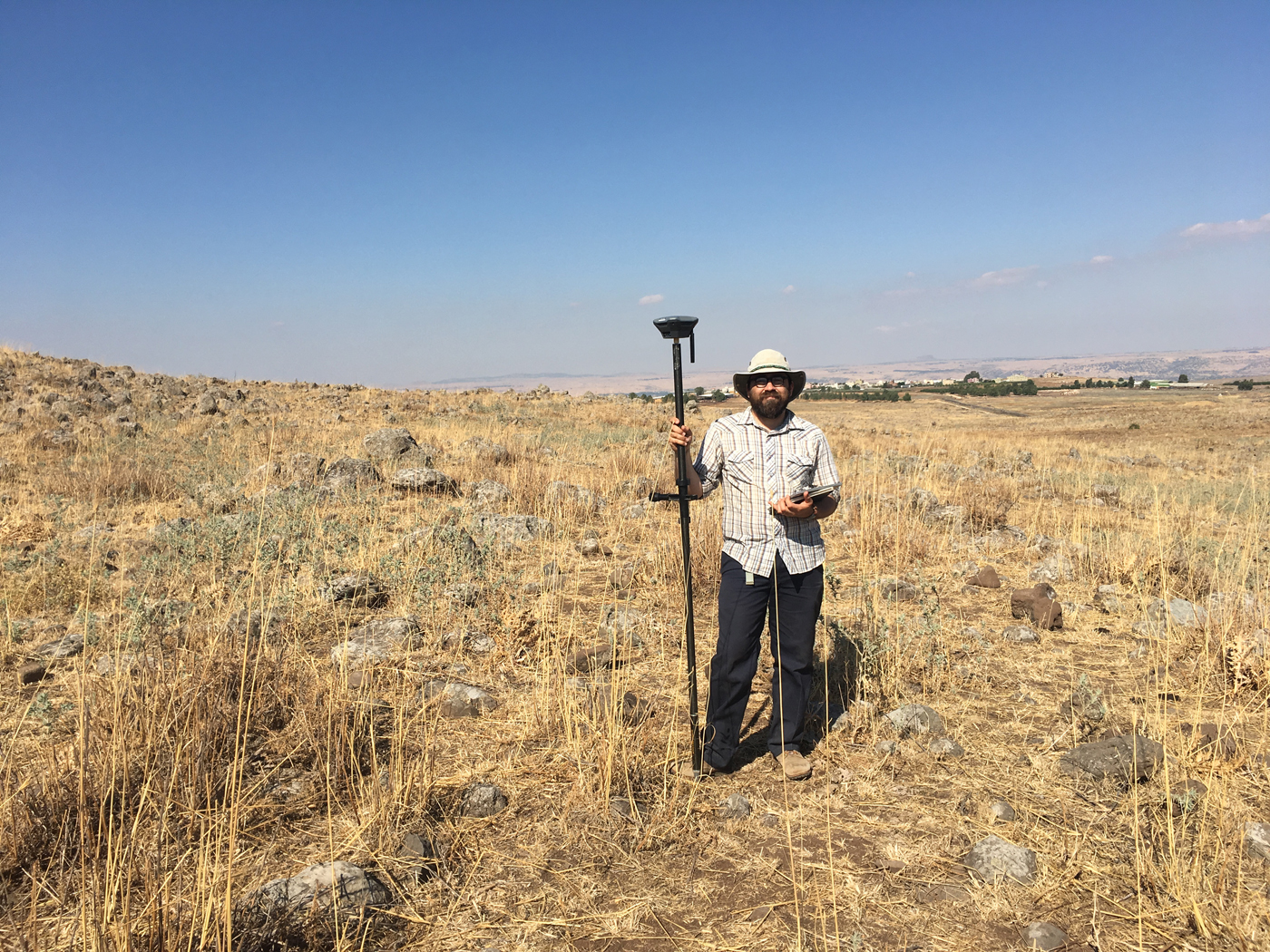
FIGURE 2. Author (Hill) at Tel Nes with Reach RS and a Windows tablet for data collection (courtesy of Yorke Rowan and the Galilee Prehistory Project).

FIGURE 3. Hill-shaded digital elevation model (DEM) of Tel Nes, Israel, derived from low-elevation drone photography and Reach RS–derived GCPs (courtesy of the Galilee Prehistory Project).
FIGURE 4. Orthophoto closeup showing UTM-based site grid of an excavation area of Tel Nes, Israel, derived from low-elevation drone photographs, Reach RS-derived GCP data, and Reach RS-derived grid stakeout (courtesy of the Galilee Prehistory Project).
The extreme portability of the Emlid Reach system was also used successfully in a drone survey of a late prehistoric Puebloan site in northern New Mexico in July 2017. In this case, no nearby RTK correction was available because the survey was conducted in a remote region where equipment had to be carried in. To lighten the weight of the equipment needed, we used an ordinary camera tripod to set up one Reach unit as a base station and simply averaged its location. We then used a second unit as a rover mounted on a collapsible camera monopod. We easily collected all the ground control points used for the survey with accuracy of a few centimeters. By also collecting coordinates of several nearby power lines and other fixed features, the resulting imagery could be subsequently georeferenced if necessary.
However, in other field experiments, we had more difficulty with the Emlid Reach RS, and prospective users should be aware of the potential limitations of these low-cost instruments. For example, we attempted to use the Emlid Reach to collect ground control points as part of a drone survey at Tlaxcala, Mexico, in May 2017. Having no local RTK correction service, we first established a fixed point using an iG3s static GNSS, and then attempted to collect the GCPs using one Reach as a base and one as a rover. While the study area was on a mountaintop with a clear view of the sky, it was adjacent to a steep canyon, and this created sufficient multipath error that we were unable to acquire an RTK fixed solution for any of the ground control points located in view of the canyon. Fortunately, we had sufficient ground control points located on the high points across the site to enable georeferencing of our imagery, but this may create a problematic limitation in some survey areas. Similarly, in a drone survey at the late prehistoric site of Etzanoa in southeastern Kansas during April 2018, we used the Emlid Reach to record ground control points. After setting up one Emlid Reach as a base station on a known point, we had to restart the system numerous times after losing fixed status on the rover, likely because nearby trees blocked part of the horizon, before eventually collecting all the ground control points.
Perhaps our most challenging experience with the Emlid Reach was in August–September 2017, when we sought to use it as our primary surveying instrument for excavation and geophysical survey on the Sirwan Regional Project and Khani Masi excavations in the Kurdistan region of Iraq. In this case, we had many of the same issues described above, in which interference from multipath errors, problems with communication between the base and rover, or glitches in software caused the system to periodically fail. On a drone survey where only a few ground control points needed collection, we generally were able to work through the issues we encountered and successfully complete the survey. However, in the context of a multiscalar excavation and survey project that necessitates frequent point collection on a time sensitive basis, particularly in the absence of nearby broadcast RTK correction signals, the unpredictable failure of the Emlid Reach system proved to be a handicap and a source of frustration in the field. While many of these problems were reduced significantly in 2018, possibly due to improvements in the Reach RS firmware, the Reach RS system might best be augmented by the continued use of a total station, where applicable, for local, rapid, and accurate point-data collection.
CONCLUSION
Low-cost systems like the Reach RS can provide excellent position information with relatively short acquisition times as long as there is a clear view of the sky, no multipath error sources, and a short baseline distance. The performance of single-frequency receivers like these deteriorates beneath vegetation, beside buildings, or in other locations that reduce satellite access. Because it has the option to output coordinate information via a Bluetooth or Wi-Fi connection, a variety of low-cost data-recording options are available. These instruments can be useful for archaeologists doing a variety of spatial data collection, including landscape surveys over several kilometers, setting up excavation units, mapping terrain around sites, and placing ground control points for drone-based mapping. It should be straightforward to develop a sophisticated field data-recording strategy that enables the recording of complex attributes with high-quality, three-dimensional coordinates. The major reduction in cost versus traditional systems, along with the wide range of deployment options, makes these systems an important new tool for a variety of archaeological projects.
Acknowledgments
Thanks to Morag Kersel and Yorke Rowan, directors of the Galilee Prehistory Project, for their help and support with the work at Tel Nes. Thanks also to the anonymous reviewers, whose comments and suggestions were of great value. Although all hardware used in the preparation of this manuscript was purchased by the authors, Emlid has donated some additional hardware to the corresponding author for use in a different project. No permits were required for this work. This work was supported by an NSF Archaeometry Award (#182210), an NSF Archaeology Award (#1724488), an NEH Digital Humanities Advancement Grant (HAA-256086-17), and a CompX Award from the Neukom Institutute for Computational Science at Dartmouth College.
Data Availability Statement
The raw data files used to calculate GNSS results in this paper will be available at https://n2t.net/ark:/87296/s6159w.


