


Nomenclature
Abbreviations
- AAR
-
Air-to-Air Refuelling
- ACP
-
Airload Computation Point
- ADS
-
Aeronautical Design Standard
- AMSL
-
Above Mean Sea Level
- AVES
-
Air Vehicle Simulator
- BWR
-
Bedford Workload Rating
- CAS
-
Calibrated Airspeed
- CFD
-
Computational Fluid Dynamics
- DAFCS
-
Digital Automatic Flight Control System
- DLR
-
German Aerospace Center
- F(AI)2R
-
Future Air-to-Air Refuelling DLR project
- FMTA
-
Future Military Transport Aircraft
- GHM
-
Generic Helicopter Model
- HAAR
-
Helicopter Air-to-Air Refuelling
- HQ
-
Handling Qualities
- HQR
-
Handling Qualities Rating
- IR
-
Infrared
- MTE
-
Mission Task Element
- PIO
-
Pilot Induced Oscillation
- RQ
-
Ride Qualities
- TS
-
Turbulent Air Scale
Symbols
- d x
%
Longitudinal Cyclic Input
- d y
%
Lateral Cyclic Input
- d p
%
Pedal Input
- d 0
%
Collective Input
- gain
-
Indices for Gain Bandwidth Value
- min
-
Indices for Minimum Value
- p
(rad/s)
Roll Rate
- q
(rad/s)
Pitch Rate ${\rm{pk}}$
-
Indices for Peak Value
- phase
-
Indices for Phase Bandwidth Value
- S(t, f)
(rad²/s²)
Rotational Rate Power as a function of Time and Frequency
- V w
(m/s)
Magnitude of Flow Field Velocity Components
- x
(m)
Helicopter Fixed Longitudinal Distance
- y
(m)
Helicopter Fixed Lateral Distance
- z
(m)
Helicopter Fixed Vertical Distance
- $\alpha$
(deg)
Angle-of-Attack
- Δ
Difference
- $\theta$
(deg)
Indices for Pitch Attitude
- ${{{\tau }}_p}$
(s)
Response time
- $\phi $
(deg)
Roll Attitude
- ${{\psi }}$
(deg)
Yaw Attitude
- ${{{\omega }}_{ - 180{\rm{deg}}}}$
(rad/s)
Frequency at -180 deg phase
- ${{{\omega }}_{{\rm{BW}}}}$
(rad/s)
Bandwidth Value


1.0 Introduction
1.1 Motivation
Performing Air to Air Refuelling (AAR) extends the mission range and duration of helicopter operations. This ability can also be used to allow a more efficient deployment of aircraft. For example, using AAR, an aircraft can perform a take-off with a high payload and limited fuel and subsequently refuel in-flight during a more efficient flight state. The benefit of AAR led to the decision of prioritised development within Europe [1], and AAR itself continues to see active deployment and use in the United States [Reference Bedard2].
The strategic importance of future AAR capabilities has been shown in recent international initiatives [3]. Since long-range and other missions that rely on AAR are predominated by fixed wing aircraft, so far little interest had been on helicopter AAR (HAAR) research and development [Reference Thomas, Bhandari, Bullock, Richardson and Du Bois4]. Concerning fixed-wing aircraft, automatic AAR has already been demonstrated [5]. Nevertheless, a potential increase of HAAR in maritime scenarios, search and rescue (SAR) operations and future autonomous SAR operations draws attention of armed forces [Reference Thomas, Bhandari, Bullock, Richardson and Du Bois4]. In October 2020 a Letter of Intent was signed by five NATO members regarding cooperation on development of Next Generation Rotorcraft Capabilities. Here, AAR was specifically highlighted as a future operational requirement [3]. Furthermore, the European Defence Agency (EDA) classified HAAR as an important force multiplier and associated equipment as essential in state-of-the-art aircraft [1]. Since HAAR is one of the most demanding tasks for military helicopter pilots and often a critical part of a mission, automation of the manoeuver will most likely be prioritised in future EDA projects.
There are currently two viable methods used to conduct AAR – the boom-and-receptacle, and probe-and-drogue method. Typically, HAAR is performed using the probe-and-drogue method since a helicopter receptacle is impractical. The probe-and-drogue method uses a tanker aircraft (typically a large fixed-wing aircraft) that deploys a drogue extended from a flexible hose. A refuelling probe is attached to the helicopter. The manoeuver is performed by precisely positioning the probe within the drogue. Contact must be maintained by the helicopter to continue refuelling, which can typically last for 6–8 minutes, depending on the amount of transferred fuel and the fuel flow rate. Figure 1 shows an external view of a typical scenario modelled in simulation.
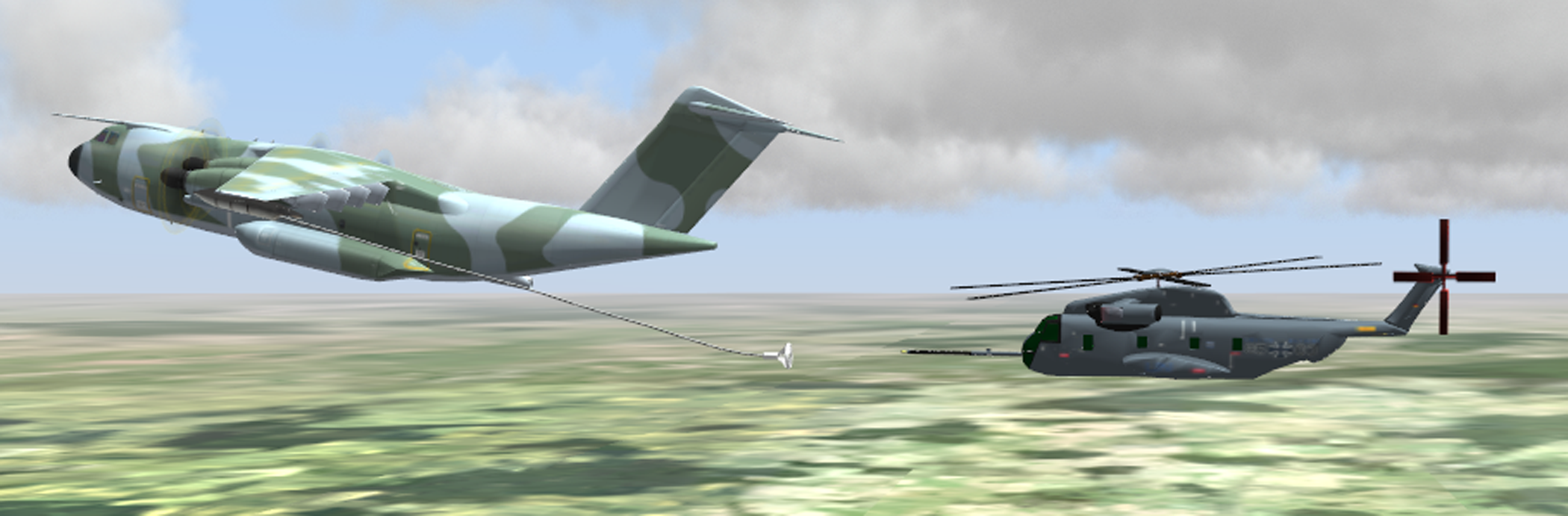
Figure 1. AVES simulation setup for HAAR.
A significant drawback of AAR operations is the associated cost, particularly concerning continued training and operations. The requirement for multiple aircraft and the complexity of operational requirements increases the cost of operations. Whilst this is not necessarily a problem for critical missions, it is a problem for training and currency. Military deployment is likely to be sporadic, depending on the conflict or mission requirements.
The use of pilot-in-the-loop simulation to conduct training can significantly reduce the cost and increase the efficiency of AAR missions. To date, however, there is a lack of simulation facilities for AAR training in Europe and for HAAR training in general. Even if the training simulation for fixed-wing AAR is improved, whereby pilots benefit from a zero-flight time training [Reference Schmidt and Jones6] (training entirely carried out in a simulator), there is a demand for research to define simulation requirements. For example, it is important to identify which elements of the dynamic environment must be modelled. Furthermore, HAAR simulation fidelity should be matched to fixed wing AAR simulation for successful transfer of training. The requirement for training simulators to maintain currency is considered essential for AAR operations to be viable, particularly in Europe. First attempts for standardised AAR simulation requirements are currently pursued by a working group of the Aerial Refueling Systems Advisory Group (ARSAG) [7].
HAAR is a complex manoeuver, where normally both the helicopter and the tanker aircraft operate at their limit flight envelopes; the helicopter at its high-speed limit, and the fixed-wing tanker at its low-speed limit. It is also acknowledged that the airflow wake from the tanker aircraft can cause a significant disturbance on the receiving helicopter. This is a particular problem due to the position of the hose and drogue, the propellers of the tanker, and the flap configuration required to allow the tanker to fly at low speed.
Difficulties concerning conducting HAAR have recently been experienced during the test program of the A400M [Reference Osborn8]. In 2015, flight tests revealed deficiencies when refuelling using an 80ft hose. The test pilots were not only concerned about the proximity to the tanker’s tail, but also struggled with strong turbulences induced by the tanker. This included extensive drogue movements as well as the tanker wake impact on the rotorcraft. To account for these issues, the length of the hose was extended from 80 to 120ft [Reference Mackenzie9]. This increased the distance between the helicopter and the tanker aircraft, but subsequently decreased the fuel-flow, raising the required refuelling time. One motivation of the current research is to understand why such problems occur and to investigate methods to reduce the pilot workload and increase operational effectiveness.
1.2 State-of-the-art AAR simulation
Plenty of literature is available concerning fixed wing AAR [Reference Thomas, Bhandari, Bullock, Richardson and Du Bois4]. Most state-of-the-art fixed wing simulators are modularly built up with a selection of the following models. While the tanker is often represented by a moving point mass, there had been a number of work on research efforts concerning receiver models, e.g. Refs. Reference Dogan, Elliott, Riley and Blake10 and Reference Barfield and Hinchman11. Refuelling system models, whether using a boom or a hose and drogue model, have different grades of detail. For hose and drogue models it ranges from just aerodynamic representative lumped masses serving as a drogue to multibody systems reproducing full hose and drogue dynamics, also including aerodynamic interference. Since refuelling always takes place within the tanker wake an aerodynamic interference model is another module to be used in simulators. This may include bow wave effects, which are important to fixed-wing AAR simulation but rather not for HAAR simulation. The modelling detail and the selection of models are depending on the purpose of the particular simulator (training or technology demonstrator). Matlab/Simulink is the most widely used modeling tool for AAR simulation [Reference Thomas, Bhandari, Bullock, Richardson and Du Bois4]. For visualisation the 3D animation toolbox of Simulink may be used as in Ref. Reference Campa, Napolitano and Fravolini12, or the model can be connected to an additional visualisation program (e.g. X-Plane, FlightGear).
To the authors’ knowledge, only limited publications are available regarding HAAR simulation. In Ref. Reference Kashawlic, Bender and Schwerke13 the evaluation of HAAR control laws during the MH-47G Digital Automatic Flight Control System (DAFCS) program was presented. Among other updates to the DAFCS, control laws for HAAR were evaluated by using piloted simulation and flight tests in order to reduce workload during HAAR. Three flights during day and night were conducted with a C-130 tanker- and HAAR-experienced Boeing and US Army test pilots. Prior to that, a real-time simulation environment had been established and tuned to behave in a realistic manner for control law development. The motion-platform-based simulator of the Boeing Philadelphia Chinook flight simulation lab was extended by a C-130 tanker model and a non-physical multi-body hose and drogue model attached to it. Both the tanker and refuelling model could independently be influenced by a white noise turbulence model. The contact simulation between probe and drogue was not featured within the program.
Currently, procedural training is performed in simulation facilities like the HH-60G Pave Hawk simulator at the Kirtland Air Force Base in Albuquerque, New Mexico, USA. The simulator features an electric motion platform and a level D flight model, including tanker wake turbulence effects [14]. With the update to the HH-60W, a new weapon system training simulator was put into operation, but is not certified for training yet [Reference Cochran15].
1.3 Scope of research
The paper presents results from an initial simulation campaign evaluating a HAAR scenario constructed within the research Air Vehicle Simulator (AVES) of the German Aerospace Center (DLR). This work forms part of the DLR project Future Air-to-Air Refuelling (F(AI)²R). The aim of the F(AI)²R project is investigating the use of simulation for probe-and-drogue AAR, in terms of fixed-wing, rotary-wing and unmanned aircraft. Moreover, concepts for actuated refuelling drogues will be considered.
Efforts were initiated within the DLR project LUBETA, described in Ref. Reference Fezans and Jann16. This project focused only on fixed-wing aircraft, with a sophisticated model of the tanker, receiver, refuelling system and aerodynamic interference. These models had been implemented in AVES for piloted real-time simulation.
This paper proceeds as follows. Firstly, general HAAR procedures are introduced. After this general understanding is built up, the development of the simulation models utilised for piloted simulation is presented. This includes the scenario itself, the receiver rotorcraft with corresponding baseline handling qualities and the tanker wake interference model extended by the real-time consideration of the tanker’s (flow field’s) rotational movements. Afterwards, evaluation methods for HAAR scenarios are examined aiming for future Mission Task Elements (MTE) leading to the actual experimental procedure applied within piloted simulation. Results of the simulator tests are then discussed followed by a conclusion of this work and an outlook for future work.
2.0 Haar procedures
This section details standard procedures used when conducting HAAR operations. The manoeuver consists of four different phases: rendezvous, join-up, contact and refuelling. Actions must also be undertaken subsequently to a successful refuelling in the post-AAR phase.
Following the rendezvous phase, the tanker inherits formation lead during the join-up phase. Typically, the hose is also unwound within this phase, releasing the drogue from the so-called wing pod. This wing pod is attached close to the wing’s tip underneath the wing. Due to strong turbulences often occurring directly behind the tanker, centreline refuelling is not envisaged for HAAR.
Join-up is completed when the receiver is placed in the observation position, which is about 100ft aft the tanker and 200ft off the tanker’s port side wing tip, as seen in Fig. 2. Usually, HAAR is performed on the port side when only a single receiver requires refuelling. The observation position serves as a waiting position and is typically above the main wing, maintained by the use of visual references on the tanker aircraft. Moreover, this position is characterised by little to no turbulences induced by the tanker. The helicopter stays to the observation position until ready to take further actions in the refuelling phase.

Figure 2. Transition from observation position to pre-contact and refuelling position [Reference Schmidt and Jones6].
Once cleared to continue, the receiver pilot should lose altitude (1), manoeuver laterally towards the tanker (2) and close up to the drogue (3) [Reference Schmidt and Jones6]. The receiver pilot should stick to this sequence in order to avoid encounters with the tanker’s downwash during the assumption of the port side pre-contact position. Again, the pre-contact position is maintained by experience-based judging of visual references. For example, when performing HAAR in the United States, utilising a C-130 tanker aircraft, the United States Air Force (USAF) logo on the tanker’s fuselage aids the pilot to judge the 5–20ft longitudinal separation of the receiver’s probe tip and the drogue.
As soon as the helicopter is stabilised in the pre-contact position, the drogue’s movements are observed by the receiver pilot. During a quiescent phase the pilot will initiate an attempt for contact. The 140lbf pressure required to engage the probe and drogue coupling shall be overcome by a closing rate of about 2–10Kn. While attempting for contact, a phase of high-pilot gain activity is encountered. Furthermore, operating the engines at their limit, rapid accelerations are often hardly achieved in this phase. This especially impacts the manoeuvering at high-density altitudes and/or during hot weather conditions. Such conditions exacerbate the tanker’s wing movements causing the drogue to move more frequent and at larger amplitudes.
After contact is established, the receiver rotorcraft is piloted to the refuelling position by a combination of an outwards movement and an altitude gain (4). Additionally, the pilot will further close up to the tanker’s wing in order to establish the refuelling position and to place the wing pod’s hose exit in between the refuelling zone marks on the hose. To ensure refuelling safety, this zone must be maintained to sustain fuel flow from the tanker. The reeling mechanism that keeps the hose’s tension enables the receiver to simply push the hose in. Similar to prior formation positions, position keeping is supported by visual references, which are e.g. the wing tip’s alignment with the probe. Once the refuelling position is established the receiver should be able to reduce required engine power by taking advantage of the lift up effect induced by the tanker’s wingtip. Furthermore, less turbulences originating from the wake should affect the receiver in this position.
To ensure maximum drogue-rotor separation for disconnect the receiver pilot manoeuvers about 5–10ft above the contact position after the refuelling is completed. A reasonable alignment of probe and hose is also necessary to avoid off-center disconnects. If that is the case, the helicopter is slowly falling back so that the hose will be unwound to its maximum length. In contrast to the contact, about 480lbf are required to disengage the probe drogue coupling.
In general, the minimum altitude conducting HAAR shall be at 500ft above ground level (AGL) [17]. Restrictions for maximum altitudes are mostly given by the flight envelopes either of the tanker and/or the receiver. According to HAAR experienced pilots interviewed within F(AI)²R [Reference Schmidt and Jones6], operational helicopter refuelling is applied as low as possible. On the other hand, training of this manoeuver takes often place at higher altitudes, for instance 7,000ft above mean sea level (AMSL). During refuelling the airspeed depends on the performance of both aircraft and also on the refuelling equipment, e.g. the low-speed drogue can be applied between 105 and 130Kn [17]. A feasible airspeed respecting all these aspects frequently ranges from 110 to 115Kn calibrated airspeed (CAS).
This effort preliminary focuses on the port-side contact and refuelling phase and particularly on the pre-contact position. Further and more detailed information regarding each phase of HAAR are found in Ref. 18.
3.0 Simulation development
3.1 Scenario development
The simulated scenario comprises a tanker, receiver and a hose-and-drogue refuelling system. The tanker aircraft model is referred to as Future Military Transport Aircraft (FMTA). The helicopter model is representing a generic heavy lift cargo helicopter, and is referred to as Generic Helicopter Model (GHM). The hose, drogue and probe elements are modelled as a coupled multi-body system used in Ref. Reference Fezans and Jann16. This refuelling model is not yet included in the real-time HAAR simulation but utilised to determine manoeuver relevant positions. Hence, the positions of the hose and drogue are fixed relative to the tanker, which is why both components are visualised without any natural dynamics.
Prior to the development of the simulation scenario shown in Fig. 1, current operational standards were analysed, and workshops were conducted with pilots who had previous experience performing HAAR [Reference Schmidt and Jones6]. In the simulation the HAAR flight condition for FMTA and GHM was set to a velocity of 115Kn CAS (= 65.71m/s true airspeed) at 7,000ft (2,134m) altitude AMSL. The FMTA’s high-lift flaps were in flap position 3 (i.e. 30 deg deflection). To evaluate the FMTA’s flight state, it is trimmed in forces by changing the angle-of-attack and the propeller’s pitch angle. This led to an angle-of-attack of 11.7 deg. The propellers were modelled as actuator disks, to offer a quasi-steady state Computational Fluid Dynamics (CFD) solution of the rotating propellers. In combination with the propeller’s speed of 860rpm and the pitch angle the propeller’s downstream can be modelled depending on the propeller diameter. For this flight condition, a CFD solution was determined in Ref. Reference Löchert, Schmidt, Jann and Jones19 and implemented within the simulation scenario as a time invariant wake.
The tanker’s wake flow was simulated using a scale resolved CFD method the improved delayed detached eddy simulation (IDDES). The wake flow of the FMTA and its potential impact to HAAR is described in Ref. Reference Löchert, Schmidt, Jann and Jones19. Figure 3 shows the wake flow topology of the FMTA under the HAAR flight condition. The figure shows the vorticity orthogonal to the y-z plane and referred to $\pi $
on slices through constant x-values from
$\pi $
on slices through constant x-values from $x = 20{\rm{m}}$
to
$x = 20{\rm{m}}$
to $x = 100{\rm{m}}$
with
$x = 100{\rm{m}}$
with $\Delta x = 10{\rm{m}}$
. For the HAAR simulation scenario the tip vortex and the flap vortex highlighted in Fig. 3 are of crucial importance.
$\Delta x = 10{\rm{m}}$
. For the HAAR simulation scenario the tip vortex and the flap vortex highlighted in Fig. 3 are of crucial importance.

Figure 3. FMTA’s wake flow topology under HAAR flight condition [Reference Löchert, Schmidt, Jann and Jones19].
In order to approximate the position of the low-speed drogue relative to the tanker, a refuelling system model (in Matlab Simulink) is applied for both the 80ft and the 120ft hose length. A more detailed description of the multi-body refuelling system including the parameter sets for both hose lengths can be found in Ref. Reference Löchert, Schmidt, Jann and Jones19. The influence of the tanker wake on the hose and drogue is also considered for the estimation of the drogue’s position.
At the given conditions, the simulation results in a drogue position [−24.2m, −3.0m, 6.3m], relative to the wing pod’s hose outlet for the 80ft case. The drogue’s relative position in the 120ft case is determined with [−35.0m, −3.0m, 10.8m]. Since the coordinates are inherent to the tanker’s body-fixed frame both hose lengths lead to a position behind, below and on the left of the wing pod. Figure 4 shows the hose’s shapes and the drogue’s positions with respect to the first joint at the hose outlet. Since the refuelling system model had not yet been implemented into the real-time helicopter simulation for these initial evaluations, the hose’s and drogue’s positions were fixed relative to the FMTA during piloted simulation.

Figure 4. Relative position of low-speed drogue (115Kn CAS; 7,000ft AMSL).
Within the AVES test facility, the tanker FMTA was simulated and displayed in the external visual environment. The aircraft motion was simulated using the Vehicle Control traffic server described in Ref. Reference Maibach, Jones and Strbac20. The tanker was configured with a constant airspeed and heading. Through discussions with pilots and through NATO guidance documents [Reference Schmidt and Jones6, 18], it is known that cases during turns and manoeuvering flight are of interest for simulation, particularly in failure or extreme situations. These cases will be explored at a later date within the project F(AI)²R but were beyond the scope of these initial evaluations. Figure 5 shows the view from the AVES cockpit during the approach to formation.

Figure 5. Cockpit view of the HAAR scenario.
In Fig. 6 the receiver helicopter is visualised maintaining both pre-contact positions for the 80ft and the 120ft hose within the tanker’s wake flow. As shown, for the 80ft hose, the strongest interference occurs at the rotor. For the 120ft hose, where the x- and z-position of the helicopter are offset, the strong region of turbulence occurs above the main rotor. These results reflect aspects reported from the initial Airbus A400M flight tests [Reference Osborn8], mentioned earlier in this paper.

Figure 6. Helicopter’s pre-contact position in tanker wake flow for the 80ft (top) and 120ft hose (bottom).
3.2 GHM development
For the real-time helicopter simulation within AVES, DLR’s 2Simulate HeliWorX modeling suite is used, featuring a non-linear implementation of a helicopter model [Reference Gotschlich and Jones21]. The HeliWorX suite originates from a Bo 105 model that applies blade element theory and was further developed to represent the Active Control Technology/Flying Helicopter Simulator (ACT/FHS). The ACT/FHS is a full-authority fly-by wire/light version of the EC135 helicopter and used for research at DLR. In this configuration, HeliWorX was extended with a real-time interference model to simulate local aerodynamic effects, like the air wake of wind turbines, ships or aircraft. Based on this extension of the HeliWorX suite, a Generic Helicopter Model (GHM) was developed and configured to represent a heavy lift cargo helicopter (e.g. CH-53). The GHM will be utilised for HAAR studies in F(AI)²R, and some of its key configuration parameters are listed in Table 1.
After completing the configuration, a three-axes SAS was manually tuned to provide a basic stability augmentation system. For this configuration, quantitative handling qualities levels were examined in terms of the bandwidth and attitude quickness criteria at the relevant flight condition. Gain and phase bandwidth values for the pitch, roll and yaw axes are summarised in Table 2. Results with respect to boundaries for target tracking and acquisition tasks are shown in Fig. 7. It is shown that Level 1 is achieved on all three axes for the bandwidth criterion.
In the Aeronautical Design Standard (ADS) 33E-PRF [22], only the roll attitude quickness is required to be evaluated in forward flight. Lateral step inputs for both left and right inceptor deflection, combined with the responses of the GHM were recorded. The resulting attitude quickness of both directions is shown in the lower right plot of Fig. 7. As it can be seen the minimum attitude changes and the peak roll rate to peak attitude change ratio lead to Level 3 handling qualities in both cases.
Table 1. Key configuration parameters of the GHM

Table 2. Gain and phase bandwidth values of the GHM


Figure 7. GHM handling qualities according to ADS 33E-PRF [22] pitch, roll, yaw bandwidth and roll attitude quickness criterion at 115Kn forward flight.
3.3 Flow field interference
The previously mentioned real-time implementation of the time invariant flow field relies on the approach outlined in Ref. Reference Maibach, Jones and Strbac20. Stored within a three-dimensional lookup table, the flow field interacts with the helicopter at defined Airload Computation Points (ACPs). Using the location of these points relative to the origin of the flow field, the local wind velocities are linearly interpolated. The ACPs are located at the rotor blades comprising ten ACPs per blade, as seen in Fig. 8. For this initial evaluation, ACPs on the fuselage, horizontal and vertical stabiliser were neglected. This was considered acceptable for first tests, but in future evaluations the additional ACPs will also be included. From previous work published in Refs. Reference Maibach, Jones and Strbac20, Reference Strbac, Martini, Greiwe, Hoffmann and Jones23 and Reference Watson, Owen and White24, the amount of ACPs on the main rotor is considered sufficient for piloted simulation. The approach uses one-way coupling only (wind table interference on helicopter), which is also considered sufficient for piloted real-time simulation. The approach has been validated through comparison between ACP output and CFD results in Ref. Reference Strbac, Martini, Greiwe, Hoffmann and Jones23.

Figure 8. Distribution of ACPs over the GHM model.
The original HAAR CFD flow field was cut to a size of +260m in length, ±80m width and ±40m height originating at the FMTA’s nose. Based on the experience of Ref. Reference Fezans and Jann16, the grid had been transformed into a structured equidistant cubic grid with a longitudinal grid discretisation of 1 and 0.5m in lateral as well as vertical direction. Since free airstream, global and local (flow field) winds are separately implemented and superimposed for force calculation later on, airstream was subtracted from the CFD solution.
The flow field is obtained in tanker body fixed coordinates from the CFD solution. To account for the tanker’s angle-of-attack, a real-time rotational transformation was added to the interference model presented in Ref. Reference Maibach, Jones and Strbac20. Instead of rotating the entire flow field once prior to the simulation, only ACP relevant vectors are transformed [Reference Löchert, Schmidt, Jann and Jones19]. This way, the interference model is prepared for rotational movements of the tanker in future work, even for larger flow fields. Yet the tanker is realised as a simple point of mass, in straight and level flight at 115Kn. The flow field origin matches the point of mass and sticks to its translational movements.
The flow field velocities at the rotor hub reference ACP obtained from the trim in the real-time simulation were compared to the velocities at the ideal pre-contact position within the original flow field of the CFD solution. Using the transformation mechanism at a static rotation around the y-axis in the real-time simulation, nearly the same velocity components could be observed in Ref. Reference Löchert, Schmidt, Jann and Jones19. Therefore, the implementation of the transformation is found to be suitable to account for the tankers angle-of-attack.
4.0 Scenario evaluation
4.1 Development of HAAR MTEs
Currently, the state-of-the-art design standard, commonly used for rotorcraft development, is ADS33E-PRF [22]. Although forward flight characteristics and ‘mission tasks’ are included in ADS33 it is focused on low-speed test and evaluation. This has been recognised in the community, and ongoing efforts are underway to update criteria for future military capabilities [Reference Berger, Cox, Wood, Ott LTC and De Cecchis25]. In this research effort, the first steps have been taken to define a new repeatable MTE to evaluate handling qualities (HQ) during the HAAR scenario. These will also aid the evaluation of future HAAR assistance and automation systems.
In Ref. Reference Kashawlic, Bender and Schwerke13 three simple flying tasks representing different parts of the contact and refuelling phase were defined. Whilst one of the tasks is directly dedicated to assess the contact and another one to the refuelling period, the third one is used to evaluate the pre-contact position. Hence, the latter task also begins in pre-contact position with the probe tip about 10–15ft aft the drogue and the longitudinal axis of both aligned. After the pilot declares he has stabilised a 30s countdown is started, which is the time the position should be maintained. In Ref. Reference Kashawlic, Bender and Schwerke13 an infrared (IR) illuminator was mounted to the probe which enabled probe drogue alignment evaluation to the pilot and crew. The limits were defined as desired when the IR marker stayed on the drogue’s coupler and adequate in case the IR marker stayed within the parachute material.
4.2 Experimental procedure
In this initial research effort, only the pre-contact phase has been considered, based on the procedure described in Section 3.0. Hence, the mission task is initiated maintaining the observation position outside of the tanker wake. The participating pilots are required to transition in the sequence described in Section 3.0 to begin close formation flight. This is the period of flight prior to the pre-contact position and, therefore, no performance requirements are defined for this segment of the manoeuver. Once stabilised in the pre-contact position 10ft behind the drogue, the formal evaluation is initiated. The pilot is required to hold the helicopter in the desired position for 30 seconds.
Initial position accuracy requirements are proposed for this segment of the task. The drogue used in this investigation has an outer diameter of 1.17m. During the hook-up manoeuver, the pilot must accurately position the probe in order initiate refuelling. Failing to achieve the correct position may result in damage to the drogue and/or to the helicopter. At this phase of the manoeuver, very high accuracy must be achieved. During the pre-contact position, although this level of precision is not required, a high level of accuracy should be demonstrated. Specifically, for these initial evaluations, it is also important to ensure that pilots perform a stable formation in the same position, to compare the subjective assessment from the same position in the static flow field. For these reasons, initial tolerances are defined as shown in Table 3. Figure 9 shows the lateral and vertical limits with respect to the drogue size. This gives an indication how the defined precision relates to the eventual precision required during the hook-up phase of the AAR task.
Table 3. Flying task limits


Figure 9. Proportional visualisation of flying task limits.
During completion of the task, lateral, vertical and heading tolerances can be visually judged by the pilot quite easily. On the other hand, difficulties occur judging the longitudinal distance due to the lack of depth perception within the simulator. Therefore, the longitudinal distance to the ideal pre-contact position is numerically displayed to the pilot. At the same time the flight test engineer has an overview of the deviations in the three axes as well as the heading. These time domain plots additionally display the defined performance boundaries so that the graphs can be used to later determine pilot performance achieved during the task.
The piloted simulations for the evaluation were conducted in AVES, using the motion platform. Due to the large motion excursions expected during completion of the scenario, the motion was tuned with low-motion gains, to ensure that no false cueing was experienced from reaching actuator limits. Each condition was flown multiple times prior to formal assessment, to ensure that the pilot reached a comparable level of performance. The pilot is asked to assess Handling Qualities Ratings (HQRs) and Bedford Workload Ratings (BWRs). For tests with active flow field interference, pilots were asked to additionally award two ratings regarding the turbulence: using the Turbulent Air Scale (TS) and a Ride Qualities (RQ) scale. These scales are discussed in further detail in the following section.
4.3 Turbulence rating scales
The TS, shown in Table 4, is a 10-point scale, whereby the pilot is asked to assess the air’s condition in terms of turbulence. Differences between the turbulence levels are defined both in terms of severity and frequency of turbulence. The method has been developed for use in flight testing [26]. The scale has been used at DLR during flight test programs to identify control equivalent turbulence models (CETI) [Reference Seher-Weiß and Jones27]. During these tests, several limitations and drawbacks of the scale were identified by the pilot. These are discussed in detail in Ref. Reference Seher-Weiß and Jones27.
Due to the limitations found when using the TS scale, a novel RQ scale was developed at DLR, particularly for use in flight tests. This scale is presented in Ref. Reference Seher-Weiß and Jones28. It is intended to be a simple method of determining the level of disturbance felt and the frequency of occurrence. The disturbance is characterised by a number and the frequency a letter. Table 5 shows the definitions for the categorisation in detail.
Table 4. Turbulent Air Scale (TS)

Table 5. Ride Qualities (RQ) scale

4.4 Discussion of results
Due to limited simulator availability, only a single pilot evaluated the scenario in this initial test campaign. The pilot had experience with all assessment methodologies used as well as limited previous experience flying a CH-53 aircraft (about 150 flight hours), typical to the GHM simulated. The pilot had no experience flying AAR missions and, therefore, could not give significant feedback as to whether the scenario was realistic. As the task was new to the pilot, a significant number of training runs were performed prior to any formal evaluations.
An initial issue the pilot encountered whilst completing the task was the lack of available cueing to adequately judge the longitudinal distance relative to the drogue. The introduced numerical indicator was therefore found beneficial in order to meet the performance requirements consistently. Nonetheless, the pilot also reported a proneness for low-frequency pilot-induced oscillations (PIO) when mainly focusing on the displayed distance. This aspect might be attributed to the combination of higher relative velocities, the pilot’s reaction time and the stringent longitudinal performance criteria. Further methods to provide relevant information to the pilot to complete the task will be investigated in future work.
Table 6 shows the ratings obtained during the investigation. Simulations conducted without the disturbance from the flow field (inactive tanker wake) were conducted first to determine the task’s realism and difficulty prior to the activation of the flow field (active tanker wake). As the flow field was not activated, neither large change in the ability to complete the task with changes to the visual scenario respectively position were expected nor that HQRs would vary between the cases.
Table 6. Ratings obtained from the pilot during simulator tests

The pilot achieved desired performance, but stated that it was difficult to obtain and therefore awarded HQR 4 for the case with inactive tanker wake. This corresponds to a qualitative HQ Level 2, whereat the quantitative baseline HQ, determined in Section 4.2, predicted Level 1 for small amplitudes in all axes. For moderate amplitudes in the roll axis, only Level 3 was predicted. However, the pilot was neither used to formation flight nor to HAAR, which means more training could have reduced the pilot’s impression of difficulty. Another aspect mentioned by the pilot was the still missing depth perception. Even with the distance numerically provided to the pilot, in fact helping to achieve desired performance, the benefits of depth perception could not be utilised to free the pilot’s capacities. Both these aspects, more training and depth perception respectively more intuitive cueing, might help to improve performance.
The workload ratings awarded reflect HQRs awarded and confirm that the task requires moderate workload even without the addition of the disturbance from the flow field. The rating indicates that the pilot had insufficient capacity to complete additional tasks whilst performing the manoeuver. The pilot stated that the rating was due to the considerable compensation required in the longitudinal axis. This was minimal in the other axes. Furthermore, the pilot stated that the workload rating depends on the kind of additional task. Additional simple tasks (e.g. providing information about conditions) would be possible throughout, but tasks requiring more attention like navigation cannot be performed.
During tests conducted with active wake interference, HQR 5 was awarded. Since the workload experienced by the pilot did not increase, the degradation of HQR could be interpreted as an inability to achieve desired performance at similar pilot effort. For both cases, with the 80 and 120ft hose length, the pilot awarded similar HQRs. This indicates little differences between both pre-contact positions. The pilot indicated that the task with the 80ft hose length caused slightly less workload than the equivalent 120ft hose scenario. As the pilot first flew the 120ft hose case, this may have been an effect of training and should be investigated in future research efforts.
The pilot’s workload rating was unchanged by the presence of wake disturbance. Pilot comments were similar to the case with and without tanker wake interference. The additional disturbance from the tanker wake did not generally increase workload.
Tendencies on both scales used to rate turbulence were found to be similar. While TS 3 on the 80ft scenario expresses light turbulence requiring corrections in manual control, TS 4 was awarded during the 120ft scenario. Hence, the turbulence within the latter scenario, described by continuous small bumps, is considered moderate. This means the pilot noticed stronger turbulence on the 120ft scenario, which is contrary to results expected prior to the pilot tests. Furthermore, the pilot’s RQ ratings confirm this tendency by increasing the turbulence category from light frequent disturbance (RQ 1-C) in the 80ft scenario to light persistent disturbance (RQ 1-D) in the 120ft scenario. Nevertheless, the wake velocity magnitudes at the rotor hub reference ACP (Vw), shown in Fig. 10, expose higher absolute velocity during the 80ft scenario, reflecting the results from the CFD analysis.

Figure 10. Time history plots of the station keeping phases.
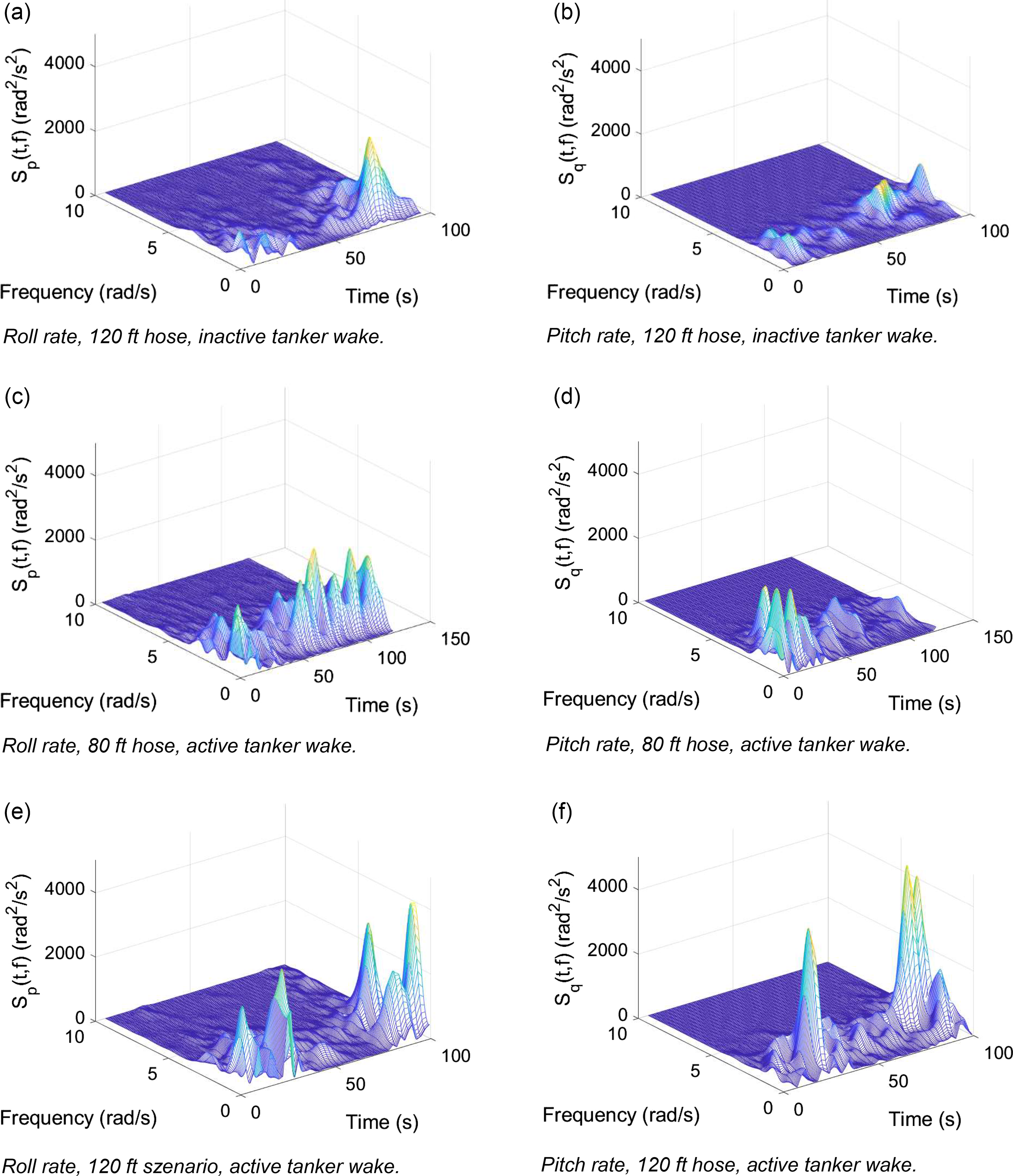
Figure 11. Time varying spectograms of GHM’s rotational rates.
Once fully stabilised, the steady flow field does not provide huge changes in wind velocity. The changes are originated in the helicopter’s movements induced by the pilot, which can be seen in Fig. 10. In the 120ft scenario the pilot notices proximity to the lower boundary in longitudinal direction (Δx) at about 18s, indicating an overshoot relative to the ideal pre-contact position. To remain within the margins the pilot excessively uses the collective (d0) to reduce speed at 19s, but rapidly comes close to the upper boundary due to overcontrolling. Such a PIO is exemplary of the previously mentioned proneness to PIO and might be avoided by training in this specific case. Starting from the initial intense collective input until ‘recover’ at about 28s the largest changes in tanker wake velocity (Vw) occur. This indicates wake velocity magnitude is provided by the flow field but wake velocity dynamics affecting the helicopter are induced by the pilot.
In Ref. Reference Lampton and Klyde29 tendencies were demonstrated that pilot effort can be described by the activity of power in time frequency spectrograms of the helicopter’s rotational rates. The rate’s power activity, summarised by the average of the time varying power frequency, was found to correlate to HQR. The pilot’s effort distribution over time and frequency can thus contribute to the identification of effort driving factors and possible changes in control strategies. Nonetheless, it must be kept in mind that some aspects (e.g. degraded control power) reduce the correlation and therefore validity.
The spectrograms of the roll and pitch rate during a complete HAAR evaluation run are visualised in Fig. 11. The lowest power activity can be seen in the 120ft scenario with inactive tanker wake (a, b). Medium activity is observed at the 80ft scenario and the highest activity shown by the 120ft scenario, both with active tanker wake disturbance. This also reflects the ratings given by the pilot. While the 120ft scenario is generally characterised by higher activity in the begin and end of a run and lower activity during longitudinal close up, the characteristic is not as pronounced in the 80ft scenario (Fig. 11; c, d). This may be attributed to the pilot’s strategy change to mainly perform the manoeuver by visual references. Generally, the characteristic can be explained by higher efforts to line up probe and hose in the beginning followed by smoothly closing up to the drogue. Then again higher effort is necessary to serve the performance requirements.
However, the largest peaks in power occur on the end of the 30s position keeping phase of the 120ft scenario with active wake disturbance (Fig. 11; e, f). But, the peaks only evolve during this phase. Starting the 30s phase at about 65s, power begins rising 15s later at about 80s. It is also the moment of beginning overcontrolling. In consistence with the observations of the time history diagrams, the main driver for the unexpected turbulence ratings may not be the flow field itself, but turbulence dynamics build up by the pilot.
To reduce over control, options for improved longitudinal cueing and/or an increase of the longitudinal performance requirements should be examined. Moreover, the impact considering additional flow field interaction on the fuselage, tail rotor, vertical and horizontal stabiliser should be analysed. Yet, it is also unclear how the actual drogue movements would impact position keeping and therefore impact wind velocity dynamics. Nevertheless, wake velocity changes would still be pilot induced. This theoretically means combining a trimmed helicopter with perfect position keeping, would not require huge pilot efforts at all. Thus, the tanker wake is recommended to be modeled as an unsteady time-depended flow field, or additional turbulence models should be included in future investigations.
5.0 Conclusion and outlook
The presented work outlined progress constructing a simulation scenario to perform helicopter air to air refuelling in a research simulation environment. The importance of future HAAR capabilities has been addressed in the paper, particularly concerning continuous training aspects. The following are the conclusions from this work.
A lack of standards for simulation fidelity exist for the HAAR scenario. A first scenario and initial efforts have been presented in this paper. The focus of this effort has been the contact and refuelling phase. The CFD solution, used within the real-time simulation, had been presented. In combination with a multi-body hose and drogue model, important positions regarding HAAR could be visualised within the flow field. This led to the hypothesis of issues similar to the ones occurred during A400M flight tests in 2015.
For a realistic scenario the generic helicopter model was developed based on the 2Simulate HeliWorX suite. Representing a heavy lift cargo helicopter the GHM will be utilised as receiver for further HAAR investigations. Initial baseline quantitative handling qualities criteria considered appropriate for the HAAR case were examined and presented. A static tanker wake flow field, determined using CFD analysis, was implemented in the real-time simulation environment.
First steps were taken to define a new mission task element for the HAAR pre-contact phase. Initial performance requirements were defined, considered reasonable with respect to the task performance requirements expected during the scenario.
An initial evaluation was undertaken with a test pilot. The pilot awarded handling qualities ratings, Bedford workload ratings and performed an assessment of turbulence using two scales, the turbulent air scale and the ride qualities scale. The pilot performed the assessment at two conditions: one with an 80ft hose and one with a 120ft hose, both with tanker wake interference. Additionally, the 120ft scenario was assessed without wake interference to create a baseline of the task.
Time history as well as time frequency analysis were performed on the data recorded during evaluation. The results show that position keeping relative to the tanker is challenging. Significant workload was attributed to the task performance requirements and the change in workload due to the wake was lower than expected. Control in the longitudinal axis led to minor oscillations and pitch bobbles throughout. It is acknowledged that the pilot who performed the task had no prior experience flying the HAAR scenario.
Future efforts are planned to include wake interference on the fuselage, horizontal and vertical stabiliser as well as to analyse the impact of drogue movement. To avoid changes of tanker wake velocities on the ACPs are mainly induced by the pilot, an unsteady time-depended flow field and other kinds of turbulence models will be further pursued.
Acknowledgements
The authors would like to thank the pilots who participated in the interviews and simulation test campaigns. Further thanks are extended to those who helped to configure the scenario within the AVES facility.
Competing interests
The authors declare none.


 Open access