


Nomenclature
- ${\mathbf{a}}$
-
vector of azimuthal basis functions
-
${\mathbf{A}}$
-
multirotor azimuthal measurement matrix
-
$b$
-
primal basis function
-
${\mathbf{B}}$
-
vectorised system matrix
-
${\mathbf{C}}$
-
vectorised multirotor measurement matrix
-
$d$
-
dual basis function
-
${\mathbf{D}}$
-
multirotor radial measurement matrix
-
${e_{n}}$
-
axial unit vector
-
${\mathbf{f}}$
-
vector of radial basis functions
-
${\mathcal F}$
-
Fourier transform
-
${\mathbf{F}}$
-
vectorised system matrix
-
${\mathbf{G}}$
-
system matrix
-
$\mathrm{i}$
-
imaginary number
-
$i$
-
rotor index
-
$j$
-
rotor index
-
${\mathbf{M}}$
-
system matrix
-
$\mathrm{p}$
-
three-dimensional pressure forcing vector
-
$p$
-
pressure
-
$P$
-
axial pressure forcing
-
$q$
-
arbitrary function
-
$r$
-
spatial radial coordinate
-
$R$
-
rotor radius
-
$\boldsymbol{\mathcal{R}}$
-
Riesz operator
-
${S_D}$
-
set of modes with compact support on the disk
-
${S_G}$
-
set of modes used in the GDW model
-
${S_M}$
-
set of modes used in the Morillo model
-
$t$
-
time
-
${\mathbf{T}}$
-
system matrix
-
$u$
-
axial induced velocity
-
${\mathbf{u}}$
-
vectorised pressure parametrisation state matrix
-
${\mathbf{U}}$
-
pressure parametrisation state matrix
-
$\boldsymbol{v}$
-
freestream velocity vector
-
${\mathbf{V}}$
-
vectorised system matrix
-
$\boldsymbol{w}$
-
three-dimensional net flow vector field
-
${\mathbf{X}}$
-
flow parametrisation state matrix
-
${\mathbf{x}}$
-
vectorised flow parametrisation state matrix
-
$y$
-
three-dimensional induced velocity vector field


Greek symbols
-
$\alpha $
-
basis adjustment factor
-
${\Gamma}$
-
Gamma function
-
$\delta $
-
normalised relative distance between two rotors
-
$\theta $
-
spatial azimuthal coordinate
-
$\vartheta $
-
spectral azimuthal coordinate
-
${\Lambda}$
-
spectral radial coordinate
-
$\mu $
-
azimuthal order
-
$\nu $
-
radial order
-
$\xi $
-
interference factor
-
$\rho $
-
fluid density
-
${\Phi}$
-
velocity potential
-
$\chi $
-
skew angle
-
$\psi $
-
freestream azimuthal angle
-
${\Psi}$
-
relative angle between two rotors


1.0 Introduction
The present work is a rework of relevant parts from the thesis of the main author [Reference Matras17].
Modeling rotorcraft can be a challenging task. A testament to this is the comprehensive work of Johnson [Reference Johnson11] on helicopter theory. The modeling can be somewhat simplified by decomposing the system into a cybernetic framework where it is natural to formulate the underlying behaviour in terms of a feedback system. Doing so allows each part of the system to be modeled and analysed independently. Following the single-rotor approach shown in [Reference Joglekar and Loewy12] yields a decomposition as shown in Fig. 1, which can be extended to multirotor systems.
Mechanics and airloads are essential parts of any major work on rotorcraft mechanics and are not considered here. The authors have also published on the topic of airloads [Reference Matras, Reinhardt, Gryte and Pedersen14]. The inflow submodule is often challenging to deal with and not described to a satisfactory level for modern multirotor systems. This paper aims to present a method for modeling the weighted averaged induced flow on one or multiple coplanar rotors in a manner that is feasible for real-time control and simulation. This is done by applying a parametrisation to the linearised Euler equation in the frequency domain. With the parametric model one can compute the inflow field generated by a pressure distribution at any desired location. The model reduces to a family of dynamic inflow models described in the literature, and various delinearisations can be applied to obtain a nonlinear model. A slight variation of this theory has previously been successfully validated by the authors [Reference Matras and Pedersen15].
Figure 2 illustrates some rotor systems for which the model can be applicable.
Block diagram illustrating the proposed decomposition of rotor-systems into a feedback structure.

Illustration of rotor systems.

2.0 Literature Review
The literature on inflow modeling for a single rotor system is relatively well established. General computational fluid dynamics (CFD) approaches can yield good results if applied correctly, but suffer from significant computational burdens. Alternatives to CFD include various techniques such as momentum, vortex and potential theories, in addition to combinations of these with empirical models. A discussion on this topic is nicely covered in Ref. (Reference Peters24).
Due to the computational complexities of CFD, such models are not directly viable for real-time dynamic inflow modeling, as is the aim for this work. In such applications, one often decides to go with low state-count models. In this category, the potential methods seem to have gained significant attention and development, as detailed in the many available reviews on the topic [Reference Chen4, Reference Matras17, Reference Peters24, Reference Yu, Hong, Ferreira and Kuik31].
However, until recently, these potential models have only been able to describe the induced flow field on the same rotor disk that the forcing was applied, yielding single-rotor models.
One of the complicating factors when formulating a dynamic inflow model for a multirotor system are the aerodynamic interactions between the propellers. In such systems, not only the induced flow field on a given rotor has to be computed, but also the induced flow field from one rotor as perceived by a spatially different rotor. In a coplanar arrangement this can be achieved, as will be shown in this work, by including an appropriate parametrisation basis, while non-planar transitions involve more complex adjustments to the model as the potential flow assumption is violated.
The endeavor of adapting the potential flow methods to multirotor systems has been undertaken previously by authors such as Ref. (Reference Prasad, Nowak and Xin27) with a generalisation in Ref. (Reference Guner9). Recent contributions also involve empirical corrections to models based on potential flow methods as shown in Ref. (Reference Usov, Appleton, Filippone and Bojdo30). Other methods not involving potential methods include the fusion of momentum and vortex theory to describe the flow on the rotor and the neighbouring rotors [Reference Guner and Prasad7] and steady-state mean-to-mean inflow model for quadrotors based on circulation as shown in Ref, (Reference Luo, Zhu and Yan13). The authors of Ref. (Reference Barcelos, Kolaei and Bramesfeld1) use an advanced potential flow model with viscous corrections to evaluate the spatially nonlinear induced flow at steady-state also on a quadrotor, showcasing the necessity of modeling the induced flow with more fidelity than just an average flow. The necessity of inflow dynamics has been investigated by the authors in a former work [Reference Matras and Pedersen16], arguing for the importance of the dynamics in multirotor applications.
From the above discussion, there are three main research gaps that require attention. First, many inflow models only consider the steady-state flow, leaving the dynamics un-modeled. Secondly, to simplify deduction and make the models real-time capable, they often only describe the mean inflow, disregarding the nonlinear spatial flow perturbations. Thirdly, the available models oftentimes seem to be limited to specific applications and lack the possibility of scaling fidelity and computational complexity.
The great diversity of models might indicate the lack of a universal generalised modeling framework for dynamic inflow modeling with real-time capabilities. The aim of this work is to unite many of the previous works by formulating a dynamic inflow model with adjustable fidelity in a generalised manner, filling the research gaps mentioned above.
3.0 Modeling
The overall modeling procedure starts by formulating the governing equations, which can be used to find the exact solution to the inflow problem. Then, a parametrisation of the governing equation is suggested to make the evaluation more efficient. While the parametrisation is introduced for a single rotor, it will be shown how it can be extended to the multirotor case. There are other ways of parametrising the flow as shown in Ref. (Reference Matras17), but we here only consider the parametrisation which is deemed the most advantageous.
3.1 Governing equation
The modeling starts with the well-known Euler equations [Reference Euler5] for flow with uniform density
 \begin{align}\frac{{\partial \boldsymbol{w}}}{{\partial t}} + \left( {\boldsymbol{w} \cdot \nabla } \right)\boldsymbol{w}= - \frac{{\nabla p}}{\rho }\end{align}
 \begin{align}\nabla \cdot \boldsymbol{w} = 0.\end{align}
Here, $w$
and
$w$
and $p$
are the nonlinear flow and pressure in spacial coordinates, respectively.
$p$
are the nonlinear flow and pressure in spacial coordinates, respectively.
Assuming first order linear flow, we have that
 \begin{align}\boldsymbol{w} = \boldsymbol{v} + y,\end{align}
where $v$
is the constant term and
$v$
is the constant term and $y$
is the first order term. Inserting this we obtain
$y$
is the first order term. Inserting this we obtain
 \begin{align}\frac{{\partial \left( {\boldsymbol{v} + y} \right)}}{{\partial t}}((\boldsymbol{v} +y) \cdot \nabla )\left( {\boldsymbol{v} + y} \right) = - \frac{{\nabla p}}{\rho }\end{align}
 \begin{align}\nabla \cdot \left( {\boldsymbol{v} + y} \right) = 0.\end{align}
By simplifying and removing the second order term in $y$
, we obtain a linearised first order model
$y$
, we obtain a linearised first order model
 \begin{align}\frac{{\partial y}}{{\partial t}} + \left( {\boldsymbol{v} \cdot \nabla } \right)y = - \frac{{\nabla p}}{\rho }\end{align}
 \begin{align}\nabla \cdot y = 0.\end{align}
3.1.1 Potential flow
Taking the divergence of the continuity-equation, Equation (7), yields the Laplace equation. This means that the flow can be described by a potential, under the assumption of irrotational and divergence free flow above the disk. A potential ${\Phi}$
has to exist such that
${\Phi}$
has to exist such that
 \begin{align}y = \nabla {\Phi}.\end{align}
Inserting the potential flow into the linearised Euler equation in Equation (6) we get
 \begin{align}\frac{{\partial \nabla {\Phi}}}{{\partial t}} + \left( {\boldsymbol{v} \cdot \nabla } \right)\nabla {\Phi} + \frac{{\nabla p}}{\rho } = 0.\end{align}
The gradient operator can now be extracted
 \begin{align}\nabla \left( {\frac{{\partial {\Phi}}}{{\partial t}} + \left( {\boldsymbol{v} \cdot \nabla } \right){\Phi} + \frac{p}{\rho }} \right) = 0\end{align}
and removed to obtain the linearised Bernoulli equation for unsteady potential flow
 \begin{align}\frac{{\partial {\Phi}}}{{\partial t}} + \left( {\boldsymbol{v} \cdot \nabla } \right){\Phi} + \frac{p}{\rho } = 0.\end{align}
3.2 Fourier transform
It will be advantageous to formulate the model in the spectral domain, and to work with polar coordinates due to the circular nature of the modeled actuator disks. To this end, let the two-dimensional Fourier transform of a spatial function in polar coordinates $q\left( {r,\theta } \right)$
be given as
$q\left( {r,\theta } \right)$
be given as
 \begin{align}\left( {{\mathcal F}q\left( {r,\theta } \right)} \right)\left( {{{\Lambda}},\vartheta } \right) = \frac{1}{{2\pi }}\mathop \int \nolimits_0^\infty \mathop \int \nolimits_0^{2\pi } {e^{ - ir \Lambda {\mathrm{cos}}\left( {\theta - \vartheta } \right)}}q\left( {r,\theta } \right)rd \theta dr.\end{align}
The spectral counterparts to the spatial radial and azimuthal coordinates $r$
and
$r$
and $\theta $
are
$\theta $
are ${{\Lambda}}$
and
${{\Lambda}}$
and $\vartheta $
, respectively.
$\vartheta $
, respectively.
Taking the Fourier transform of Equation (11) on the rotor plane gives
 \begin{align}\frac{{\partial {{\hat \Phi }}}}{{\partial t}} + {{\Lambda}}\left( {{\boldsymbol{\mathcal R}} \cdot v} \right){{\hat \Phi }} = {{\Lambda}}\frac{1}{{2\rho }}{\boldsymbol{\mathcal{R}}}\mathrm{p},\end{align}
as shown in Ref. (Reference Pedersen22), where ${\boldsymbol{\mathcal R}}$
is the modified Riesz operator given by
${\boldsymbol{\mathcal R}}$
is the modified Riesz operator given by
 \begin{align}{\boldsymbol{\boldsymbol{\mathcal R}}} = \left[ {\begin{array}{*{20}{l}}{\mathrm{i}{\mathrm{cos}}\left( \vartheta \right)}\\{\mathrm{i} {\mathrm{sin}}\left( \vartheta \right)}\\1\end{array}} \right],\end{align}
The Riesz operator acts as a fractional gradient operator, relating the harmonic fields in the three dimensions, see Ref. (Reference Pedersen22) for details on the topic.
We define a function for the flow over the plane by evaluating the potential ${\Phi}$
on the rotor plane where
${\Phi}$
on the rotor plane where ${e_n} = 0$
,
${e_n} = 0$
,
 \begin{align}\hat{{u}} = \frac{{\partial {{\hat \Phi }}}}{{\partial {e_n}}}{\LARGE|_{{e_n} = 0}} = {{\Lambda \hat \Phi }}.\end{align}
Dividing Equation (13) by ${{\Lambda}}$
, inserting for
${{\Lambda}}$
, inserting for $w$
and simplifying, we get the final form of the differential equation,
$w$
and simplifying, we get the final form of the differential equation,
 \begin{align}\frac{1}{{{\Lambda}}}\frac{{\partial \hat{{u}}}}{{\partial t}} + \left( {{\boldsymbol{\mathcal R}} \cdot \boldsymbol{v}} \right)\hat{{u}} = \frac{1}{{2\rho }}{\boldsymbol{\mathcal R}} \mathrm{p}.\end{align}
Furthermore, to obtain the flow in the spectral domain û , we use the Fourier transformed version of Equation (8), which gives Ref. (Reference Pedersen22).
 \begin{align} {{\hat y}} = {\Lambda} {\boldsymbol{\boldsymbol{\mathcal R}}} {\hat \Phi } = {\boldsymbol{\boldsymbol{\mathcal R}}} {\hat{{u}}}.\end{align}
This general formulation gives the induced flow $u$
in all three axis generated by the forcing
$u$
in all three axis generated by the forcing $\mathrm{p}$
in all three axis. In the following, we will only consider the forcing and inflow that is perpendicular to the rotor plane, so
$\mathrm{p}$
in all three axis. In the following, we will only consider the forcing and inflow that is perpendicular to the rotor plane, so
 \begin{align}\frac{{\dot {\hat{{u}}}}}{{{\Lambda}}} + \left( {{\boldsymbol{\mathcal R}} \cdot \boldsymbol{v}} \right)\hat{{u}} = \frac{P}{{2\rho }}\end{align}
 \begin{align}\hat{{u}} = \hat{{u}}.\end{align}
Figure 3 illustrates the physical interpretation of the system equations in a somewhat simplified fashion. The system computes the induced velocities ${{\mathcal F}^{ - 1}}\left( {\hat u} \right)$
generated by a disk of radius
${{\mathcal F}^{ - 1}}\left( {\hat u} \right)$
generated by a disk of radius $R$
subject to the generated force fields
$R$
subject to the generated force fields ${{\mathcal F}^{ - 1}}\left( {\hat f} \right)$
at freestream flow velocities
${{\mathcal F}^{ - 1}}\left( {\hat f} \right)$
at freestream flow velocities ${{v}}$
across the disk.
${{v}}$
across the disk.
Illustration of variables simplified to one dimension of $\mathrm{p}$
.
$\mathrm{p}$
.

From a mathematical standpoint, the proposed modeling strategy works as shown in Fig. 4. The model is formulated in the spectral domain, and can be retrieved using a discrete fast Fourier transform (DFFT) and the inverse DFFT (IDFFT), or by parametrising its inputs and outputs with coefficients that are invariant to the Fourier transform. The latter approach allows for fast and simple manipulation of the spectral model with inputs and outputs in the spatial domain.
Model domains, figure from Ref. (Reference Matras17).

3.3 Exact solution
Because the model is given in the spectral domain, the exact solution to Equations (18) and (19) can be computed numerically to any desired accuracy by the help of the DFFT and its inverse. Thus, any spatial forcing can be transformed into the spectral domain using the DFFT, where the dynamic Equation (18) is solved, before the IDFFT is applied to Equation (19) to recover the spatial induced flow. This technique is practical for validating the efficacy of various parametrisations and can also be used as an alternative to traditional CFD solvers. An example of this procedure is shown for the forcing in Fig. 5 and the resulting steady-state induced flow in Fig. 6.
Spatial forcing on two neighbouring disks.

Steady-state flow from forcing in Fig. 5.

3.4 Parametrisation
Having established the governing equations, one can now focus on parametrising the flow to make it computationally efficient. When seeking a parametrisation for these quantities, it is natural to choose a complete, polynomial, orthogonal basis consisting of functions that are also solutions to the Laplace equation. This allows any force or flow distribution to be parametrised to the desired accuracy. Additionally, a subset of the basis should have compact support on the disk.
A suitable basis set in the spectral domain exists [Reference Matras17] as
 \begin{align}\hat b_\nu ^\mu \left( {{{\Lambda}},\vartheta ,\alpha } \right) = {(\!- {\mathrm{i}})^{\left| \mu \right|}}\,{\mathrm{exp}}\left( {{\mathrm{i}}\vartheta \mu } \right)\frac{{{J_{\alpha + \nu + 1}}\left( {{{\Lambda}}R} \right)}}{{{{({{\Lambda}}R)}^{1 + \alpha }}}}\sqrt {2\nu + 2\left( {\alpha + 1} \right)} .\end{align}
These functions are biorthogonal with respect to the dual basis
 \begin{align}\hat d_\nu ^\mu \left( {{{\Lambda}},\vartheta ,\alpha } \right) = {{\mathrm{i}}^{\left| \mu \right|}}\,{\mathrm{exp}}\left( { - {\mathrm{i}}\vartheta \mu } \right)\frac{{{J_{\alpha + \nu + 1}}\left( {{{\Lambda}}R} \right)}}{{{{({{\Lambda}}R)}^{1 - \alpha }}}}\sqrt {2\nu + 2\left( {\alpha + 1} \right)} .\end{align}
By choosing the $\alpha $
parameter, the modes can be adjusted to fit the desired boundary conditions, see Ref. (Reference Matras17) for details on the topic. Unless stated otherwise, the remainder of this work will consider
$\alpha $
parameter, the modes can be adjusted to fit the desired boundary conditions, see Ref. (Reference Matras17) for details on the topic. Unless stated otherwise, the remainder of this work will consider $\alpha = 0$
.
$\alpha = 0$
.
The basis has the property of being radially and azimuthally decoupled in the spectral domain, which is advantageous for the model formulation and later computation. This allows the basis to be split into vector format with the radial vector ${\hat{\mathbf f}}\left( {{\Lambda}} \right)$
given by the terms
${\hat{\mathbf f}}\left( {{\Lambda}} \right)$
given by the terms
 \begin{align}{\hat f_\nu }\left( {{\Lambda}} \right) = \frac{{{J_{\alpha + \nu + 1}}\left( {{{\Lambda}}R} \right)}}{{{{({{\Lambda}}R)}^{1 + \alpha }}}}\sqrt {2\nu + 2\left( {\alpha + 1} \right)} \end{align}
and azimuthal vector ${{\hat{\mathbf{a}}}}\left( \vartheta \right)$
with terms
${{\hat{\mathbf{a}}}}\left( \vartheta \right)$
with terms
 \begin{align}{\hat a_\mu }\left( \vartheta \right) = {( \!- {\mathrm{i}})^{\left| \mu \right|}}\,{\mathrm{exp}}\left( {{\mathrm{i}}\vartheta \mu } \right).\end{align}
A similar trick can be done for the dual basis as well, obtaining ${{\hat {\bar{\mathbf{f}}}}}\left( {{\Lambda}} \right)$
and
${{\hat {\bar{\mathbf{f}}}}}\left( {{\Lambda}} \right)$
and ${{\hat {\bar{\mathbf{a}}}}}\left( \vartheta \right)$
.
${{\hat {\bar{\mathbf{a}}}}}\left( \vartheta \right)$
.
Figure 7 illustrates the modes described by the primary basis functions in Equation (20). The imaginary part is shown for $\mu \lt 0$
and the real part for
$\mu \lt 0$
and the real part for $\mu \ge 0$
. However, it can be difficult to intuitively understand the spectral modes, to this end, one can compute the spatial counterparts as shown in Fig. 8. Also here, the imaginary part is shown for
$\mu \ge 0$
. However, it can be difficult to intuitively understand the spectral modes, to this end, one can compute the spatial counterparts as shown in Fig. 8. Also here, the imaginary part is shown for $\mu \lt 0$
and the real part for
$\mu \lt 0$
and the real part for $\mu \ge 0$
.
$\mu \ge 0$
.
Illustration of spectral modes.

Illustration of spatial modes.

Computing the spatial counterparts to the spectral basis functions in Equations (20) and (21) can be done by the help of the inverse Fourier transform. This is a challenging task, one way of doing it is to use the Jacobi-Anger expansion on the kernel of the Fourier transform and then apply the Hankel transform on the remaining integrals. This allows one to compute
 \begin{align}b_\nu ^\mu \left( {r,\theta ,\alpha } \right) =&\, \,{\mathrm{exp}}\left( {{\mathrm{i}}\mu \theta } \right){\Gamma}\left( {\frac{1}{2}\left( {2 + \nu + \left| \mu \right|} \right)} \right)\sqrt {2\nu + 2\left( {\alpha + 1} \right)} \\\nonumber &\quad\left\{ {\begin{array}{*{20}{l}}{\dfrac{{{r^{\left| \mu \right|}}{{\mathrm{\;}}_2}{F_1}\left( {\dfrac{1}{2}\left( {\left| \mu \right| - \nu - 2\alpha } \right),\dfrac{1}{2}\left( {2 + \nu + \left| \mu \right|} \right),1 + \left| \mu \right|,{r^2}/{R^2}} \right)}}{{{R^2}{\Gamma}\left( {\dfrac{1}{2}\left( {2 + \nu - \left| \mu \right| + 2\alpha } \right)} \right){\Gamma}\left( {1 + \left| \mu \right|} \right)}},\,} {}{0 \lt r \lt R}\\[30pt]{\dfrac{{{R^2}{r^{ - \left( {2 + \nu } \right)}}{{\mathrm{\;}}_2}{F_1}\left( {\dfrac{1}{2}\left( {2 + \nu - \left| \mu \right|} \right),\dfrac{1}{2}\left( {2 + \nu + \left| \mu \right|} \right),2 + \nu + \alpha ,{R^2}/{r^2}} \right)}}{{{\Gamma}\left( {\dfrac{1}{2}\left( {\left| \mu \right| - \nu } \right)} \right){\Gamma}\left( {2 + \nu + \alpha } \right)}},\,} {}{r \gt R.}\end{array}} \right.\end{align}
A similar computation can be performed for the dual modes.
3.4.1 Pressure
The previously described modes are defined on the whole domain, but the pressure forcing generated by the airloads is confined to the disk. Thus, the pressure should only be parametrised in modes that have values on the disk and are zero elsewhere. These modes are said to have compact support on the disk, and following Ref. (Reference Matras17), with $\alpha = 0$
, modes that are in the set
$\alpha = 0$
, modes that are in the set
 \begin{align}{S_D} = \{ \left( {\mu ,\nu } \right) \in {\mathbb Z} \times {\mathbb Z}|\left( {\nu + \mu } \right){\mathrm{even}},{\mathrm{and\;}}\nu \ge \left| \mu \right|\} \end{align}
have compact support on the disk. This can be seen by analysing Equation (24). Describing the pressure as a linear combination of the basis gives
 \begin{align}P = \mathop \sum \limits_{\left( {\mu ,\nu } \right) \in {S_D}} {U_{\mu ,\nu }}\hat b_\nu ^\mu \left( {\alpha ,\vartheta ,k} \right) = {{\hat{\mathbf f}}^{\mathrm{T}}}{\mathbf{U}{\hat {\mathbf a}}},\end{align}
where each term ${U_{\mu ,\nu }}$
in the matrix
${U_{\mu ,\nu }}$
in the matrix ${\mathbf{U}}$
describes the weight of the given mode. While the pressure forcing is defined in the spectral domain, the coefficients in
${\mathbf{U}}$
describes the weight of the given mode. While the pressure forcing is defined in the spectral domain, the coefficients in ${\mathbf{U}}$
are invariant to the Fourier transform, so these can be used directly in the spatial domain, and vice versa.
${\mathbf{U}}$
are invariant to the Fourier transform, so these can be used directly in the spatial domain, and vice versa.
3.4.2 Flow
As shown in Ref. (Reference Matras17), there are two ways of parametrising the flow, one of which guarantees exact results at steady state, namely the parametrisation strategy referred to as the indirect parametrisation. As this guarantee is advantageous, we will follow this parametrisation strategy.
At steady state, the dynamic system equations in Equation (18) reads
 \begin{align}\hat{{u}} = {\left( {{\boldsymbol{\mathcal R}} \cdot \boldsymbol{v}} \right)^{ - 1}}\frac{{{P_{qs}}}}{{2\rho }},\end{align}
where ${P_{qs}}$
is a quasistatic forcing parametrised as shown in Equation (26),
${P_{qs}}$
is a quasistatic forcing parametrised as shown in Equation (26),
 \begin{align}\hat{{u}} = {\left( {{\boldsymbol{\mathcal R}} \cdot \boldsymbol{v}} \right)^{ - 1}}\frac{1}{{2\rho }}{{\hat{\mathbf f}}^{\mathrm{T}}}{{\mathbf{U}}_{qs}}{{\hat{\mathbf{a}}}}.\end{align}
By using this parametrisation, any steady-state flow originating from the steady-state forcing described by ${{\mathbf{U}}_{qs}}$
is accounted for to the fidelity of the basis.
${{\mathbf{U}}_{qs}}$
is accounted for to the fidelity of the basis.
3.4.3 Dynamic equation
The parametrisation of the dynamic equation is done by applying Galerkins method. Inserting the pressure and flow parametrisations into the dynamic Equation (18), one obtains the parametrised model
 \begin{align}\frac{1}{{{\Lambda}}}{\left( {{\boldsymbol{\mathcal R}} \cdot \boldsymbol{v}} \right)^{ - 1}}\frac{1}{{2\rho }}{{\hat{\mathbf f}}^{\mathrm{T}}}{{\dot{\mathbf{U}}}_{qs}}{\hat{\mathbf a}} + \frac{1}{{2\rho }}{{\hat{\mathbf{f}}}^{\mathrm{T}}}{{\mathbf{U}}_{qs}}{\hat{\mathbf a}} = \frac{1}{{2\rho }}{{\hat{\mathbf f}}^{\mathrm{T}}}{\mathbf{U}{\hat{\mathbf a}}}.\end{align}
Having Equation (29) on parametrised form, it can be solved optimally by applying the dual basis and integrating over the whole domain. This is also known as Galerkins method and ensures that any parametrisation error is orthogonal to the basis. The process yields
 \begin{align} \frac{1}{{2\pi }}\mathop \int \nolimits_0^\infty \mathop \int \nolimits_0^{2\pi } \frac{1}{{{\Lambda}}}{\left( {{\boldsymbol{\mathcal R}} \cdot \boldsymbol{v}} \right)^{ - 1}}\frac{1}{{2\rho }}{{\hat {\bar{\mathbf{f}}}}}{{\hat{\mathbf f}}^{\mathrm{T}}}{{\dot{\mathbf{U}}}_{qs}}{{\hat {\mathbf{a}}}}{{{\hat {\bar{\mathbf{a}}}}}^{\mathrm{T}}} + \frac{1}{{2\rho }}{{\hat {\bar{\mathbf{f}}}}}{{\hat{\mathbf f}}^{\mathrm{T}}}{{\mathbf{U}}_{qs}}{{\hat{\mathbf{a}}}}{{{\hat {\bar {\mathbf{a}}}}}^{\mathrm{T}}} \Lambda d\vartheta d \Lambda = {1 \over {2\pi }}\mathop \int \nolimits_0^\infty \mathop \int \nolimits_0^{2\pi } {\boldsymbol{\mathcal R}}{1 \over {2\rho }}{{\hat {\bar{\mathbf{f}}}}}{{\hat{\mathbf f}}^{\mathrm{T}}}{\mathbf{U} \hat{\mathbf{a}}}{{{\hat {\bar{\mathbf{a}}}}}^{\mathrm{T}}}{{\Lambda}}d \vartheta d{{\Lambda}}.\end{align}
The selected basis has the advantageous property that it decouples the integrals in terms of the radial and azimuthal components, so that these can be computed independently as
 \begin{align}{\mathbf{M}} = \mathop \int \nolimits_0^\infty \frac{1}{{{\Lambda}}}\frac{1}{{2\rho }}{{\hat {\bar{\mathbf{f}}}}}{{\hat{\mathbf f}}^{\mathrm{T}}}{{\Lambda}}d{{\Lambda}}\end{align}
 \begin{align}{\mathbf{T}} = {1 \over {2\pi }}\mathop \int \nolimits_0^{2\pi } {\left( {{\boldsymbol{\mathcal R}} \cdot \boldsymbol{v}} \right)^{ - 1}}{{\hat{\mathbf a}}}{{{\hat {\bar{\mathbf{a}}}}}^{\mathrm{T}}}d\vartheta \end{align}
 \begin{align}{\mathbf{G}} = \mathop \int \nolimits_0^\infty \frac{1}{{2\rho }}{{\hat {\bar{\mathbf{f}}}}}{{\hat{\mathbf f}}^{\mathrm{T}}}{{\Lambda}}d{{\Lambda}}.\end{align}
 \begin{align}{\mathbf{I}} = \frac{1}{{2\pi }}\mathop \int \nolimits_0^{2\pi } \frac{1}{{2\rho }}{\hat{\mathbf a}}{{{\hat {\bar{\mathbf{a}}}}}^{\mathrm{T}}}d\vartheta .\end{align}
This results in the system
 \begin{align}\frac{1}{{\left| \boldsymbol{v} \right|}}{\mathbf{M}}{{\dot{\mathbf{U}}}_{qs}}{{\mathbf{T}}^{ - 1}} + {\mathbf{G}}{{\mathbf{U}}_{qs}} = {\mathbf{GU}}.\end{align}
The only catch here is that the computation of Equation (32) is not straight-forward, as the velocity ${\mathbf{v}}$
has to be recast into spherical coordinates such that
${\mathbf{v}}$
has to be recast into spherical coordinates such that
 \begin{align} \boldsymbol{v} = \left| \boldsymbol{v} \right|\left[ {\begin{array}{*{20}{l}}{{\mathrm{sin}}\chi {\mathrm{cos}}\psi }\\{{\mathrm{sin}}\chi {\mathrm{sin}}\psi }\\{{\mathrm{cos}}\chi }\end{array}} \right]\end{align}
and the term ${\left( {{\boldsymbol{\mathcal R}} \cdot \boldsymbol{v}} \right)^{ - 1}}$
expanded in a Maclaurin series
${\left( {{\boldsymbol{\mathcal R}} \cdot \boldsymbol{v}} \right)^{ - 1}}$
expanded in a Maclaurin series
 \begin{align}\left| \boldsymbol{v} \right|{\left( {{\boldsymbol{\mathcal R}} \cdot \boldsymbol{v}} \right)^{ - 1}} = 1 + 2\mathop \sum \limits_{n = 1}^{{N_T}} {( \!- {\mathrm{i}})^n}{\mathrm{cos}}\left( {n\left( {\vartheta - \psi } \right)} \right){\mathrm{tan}}{\left( {\frac{\chi }{2}} \right)^n}.\end{align}
This allows the computation of the involved terms
 \begin{align}{M_{{\nu _p},{\nu _d}}} = \frac{{sinc\left( {\frac{\pi }{2}\left( {{\nu _d} - {\nu _p} - 1} \right)} \right) + sinc\left( {\frac{\pi }{2}\left( {{\nu _d} - {\nu _p} + 1} \right)} \right)}}{{R\left( {1 + 2\alpha + {\nu _p} + {\nu _d}} \right)\left( {3 + 2\alpha + {\nu _p} + {\nu _d}} \right)}}\sqrt {2{\nu _p} + 2\left( {\alpha + 1} \right)} \sqrt {2{\nu _d} + 2\left( {\alpha + 1} \right)} \end{align}
 \begin{align}{T_{{\mu _p},{\mu _d}}} = {( \!- {\mathrm{i}})^{\left| {{\mu _p} - {\mu _d}} \right|}}{( \!- {\mathrm{i}})}^{|\mu _p|}{({\mathrm{i}})}^{|\mu _d|}{\mathrm{tan}}{\left( {\frac{\chi }{2}} \right)^{\left| {{\mu _p} - {\mu _d}} \right|}}\,{\mathrm{exp}}\left( { - {\mathrm{i}}\left( {{\mu _p} - {\mu _d}} \right)\psi } \right)\end{align}
 \begin{align}{G_{{\nu _p},{\nu _d}}} = \frac{{sinc\left( {\frac{\pi }{2}\left( {{\nu _d{}} - {\nu _p}} \right)} \right)}}{{{R^2}\left( {2 + 2\alpha + {\nu _p} + {\nu _d}} \right)}}\sqrt {2{\nu _p} + 2\left( {\alpha + 1} \right)} \sqrt {2{\nu _d} + 2\left( {\alpha + 1} \right)} .\end{align}
The states of the indirect parametrisation, the quasistatic forcing coefficients in ${{\mathbf{U}}_{qs}}$
, do not represent the flow, and a measurement equation is therefore needed to recover the flow. This is found by parametrising the measured flow as
${{\mathbf{U}}_{qs}}$
, do not represent the flow, and a measurement equation is therefore needed to recover the flow. This is found by parametrising the measured flow as
 \begin{align}\hat{{u}} = {{\hat{\mathbf f}}^{\mathrm{T}}}{\mathbf{X}{\hat {\mathbf a}}},\end{align}
equating it to the flow parametrisation Equation (28) and computing the Galerkin solution yields
 \begin{align}{\mathbf{X}} = \frac{1}{{2\rho \left| \boldsymbol{v} \right|}}{{\mathbf{U}}_{qs}}{{\mathbf{T}}^{ - 1}}.\end{align}
Solving for ${{\mathbf{U}}_{qs}}$
and inserting into the dynamic Equation (35) one obtains an alternative dynamic equation, where the states directly describe the flow
${{\mathbf{U}}_{qs}}$
and inserting into the dynamic Equation (35) one obtains an alternative dynamic equation, where the states directly describe the flow
 \begin{align}{\mathbf{M} \dot{\mathbf{X}}} + \left| \boldsymbol{v} \right|{\mathbf{GXT}} = \frac{1}{{2\rho }}{\mathbf{GU}}.\end{align}
A vectorised version of Equation (43) can be computed by vectorising the equation to obtain
 \begin{align}\left( {{\mathbf{I}} \otimes {\mathbf{M}}} \right){{\dot{\mathbf{x}}}} + \left| \boldsymbol{v} \right|\left( {{{\mathbf{T}}^{\mathrm T}} \otimes {\mathbf{G}}} \right){\mathbf{x}} = {\mathbf{V}\dot{\mathbf{x}}} + \left| \boldsymbol{v} \right|{\mathbf{Fx}} = \frac{1}{{2\rho }}\left( {{\mathbf{I}} \otimes {\mathbf{G}}} \right){\mathbf{u}} = {\mathbf{Bu}},\end{align}
which is computationally less efficient than the matrix form.
The new states ${\mathbf{X}}$
are also invariant to the Fourier transform, and the flow in spatial coordinates can be obtained from
${\mathbf{X}}$
are also invariant to the Fourier transform, and the flow in spatial coordinates can be obtained from
 \begin{align}{u} = \sum b_\nu ^\mu {X_{\nu ,\mu }}.\end{align}
3.5 Visualisation
If one were to plot the states directly as they are given in Equation (45), one would obtain poor results that do not adequately describe the desired flow field. This issue arises due to numerical conditions within the model and can easily be fixed with a simple trick. Instead of plotting the states directly, one should solve the system equation
 \begin{align}{\mathbf{V}\dot{\mathbf{x}}} + \left| \boldsymbol{v} \right|{\mathbf{Fx}} = {\mathbf{Bu}}\end{align}
for the flow, such that
 \begin{align}{\mathbf{x}} = \frac{1}{{\left| \boldsymbol{v} \right|}}{{\mathbf{F}}^{ - 1}}\left( {{\mathbf{Bu}} - {\mathbf V}{\dot{\mathbf {x}}}} \right).\end{align}
Now, the flow is described as the steady-state solution ${\mathbf{Bu}}$
which is perturbed by the dynamic term
${\mathbf{Bu}}$
which is perturbed by the dynamic term ${\mathbf V}{\dot{\mathbf {x}}}$
. Doing so solves the issues and the resulting plots are as one would expect.
${\mathbf V}{\dot{\mathbf {x}}}$
. Doing so solves the issues and the resulting plots are as one would expect.
3.6 Multirotor extension
The preceding model has been formulated as a single rotor model, where the flow is evaluated on the same area as the pressure forcing is applied. The aerodynamic interactions can be included by evaluating the flow on a disk that does not coincide with the disk to which the pressure forcing is applied. As discussed in Ref. (Reference Matras17), there are two main ways of performing the multirotor extension, input and output coupling. In the input coupling type, the pressure forcing is moved, resulting in system matrices that depend on the rotor layout. The other alternative, output coupling, evaluates the induced flow from one rotor on a different rotor, where the induced flow is considered a disturbance to the freestream velocity. The latter case is simplest, as all the system matrices, except for the measurement matrix, are decoupled and only connected through the freestream velocity term.
As shown in Ref. (Reference Guner, Prasad, Sankar, Peters and He8), both the input and output coupling methods produce similar results. For reasons of simplicity, the output coupling model will be pursued here. Figure 9 illustrates the case for two rotors, where the net flow parameter for rotor $i$
,
$i$
, $\left| {{v_i}} \right|$
is the freestream flow perturbed by the induced velocity of the neighbouring rotor
$\left| {{v_i}} \right|$
is the freestream flow perturbed by the induced velocity of the neighbouring rotor $j$
. The measurement matrix
$j$
. The measurement matrix ${\mathbf{C}}_j^i$
is used to map the flow from one rotor to the neighbouring.
${\mathbf{C}}_j^i$
is used to map the flow from one rotor to the neighbouring.
Block diagram of multirotor model.

Consider the flow parametrisation in Ref. (41) shifted $\delta _j^iR$
radially and
$\delta _j^iR$
radially and ${\Psi}_j^i$
azimuthally. In the frequency domain, this shift of the evaluation area is easily achieved by using the 2D Fourier shift operator in polar coordinates, such that
${\Psi}_j^i$
azimuthally. In the frequency domain, this shift of the evaluation area is easily achieved by using the 2D Fourier shift operator in polar coordinates, such that
 \begin{align}{u} = {{\hat{\mathbf f}}^{\mathrm{T}}}{\mathbf{X}{\hat {\mathbf a}}}\,{\mathrm{exp}}\left( { - {\mathrm{i}}\delta _j^iRk\,{\mathrm{cos}}\left( {\vartheta - {\Psi}_j^i} \right)} \right).\end{align}
The flow from rotor $i$
evaluated on a different rotor disk, rotor
$i$
evaluated on a different rotor disk, rotor $j$
is thus given as
$j$
is thus given as
 \begin{align}{{\hat{\mathbf f}}^{\mathrm{T}}}{{\mathbf{X}}_j}{{\hat{\mathbf{a}}}} = {{\hat{\mathbf f}}^{\mathrm{T}}}{{\mathbf{X}}_i}{\hat{\mathbf{a}}}\,{\mathrm{exp}}\left( { - {\mathrm{i}}\delta _j^i Rk\, {\mathrm{cos}}\left( {\vartheta - {\Psi}_j^i} \right)} \right).\end{align}
Similarly to the dynamic system, the Galerkin method is applied
 \begin{align} \frac{1}{{2\pi }}\mathop \int \nolimits_0^\infty \mathop \int \nolimits_0^{2\pi } {{\hat {\bar{\mathbf{f}}}}}{{\hat{\mathbf f}}^{\mathrm{T}}}{{\mathbf{X}}_i}{{\hat{\mathbf{a}}}}{{{\bar{\mathbf{a}}}}^{\mathrm{T}}}{{\Lambda}}d\vartheta d{{\Lambda}} = \frac{1}{{2\pi }}\mathop \int \nolimits_0^\infty \mathop \int \nolimits_0^{2\pi } {{\hat {\bar{\mathbf{f}}}}}{{\hat{\mathbf f}}^{\mathrm{T}}}{{\mathbf{X}}_j}{{\hat{\mathbf{a}}}}\,{\mathrm{exp}}\left( { - {\mathrm{i}}\delta _j^iR{\Lambda {\mathrm {cos}}}\left( {\vartheta - {\Psi}_j^i} \right)} \right){{{\bar{\mathbf{a}}}}^{\mathrm{T}}}{{\Lambda}}d\vartheta d{{\Lambda}}.\end{align}
The left side is trivial, but the shift operator on the right side needs to be expanded using the Jacobi-Anger expansion before the radial and azimuthal components can be computed independently to yield
 \begin{align}{\mathbf{G}}{{\mathbf{X}}_i} = {{\mathbf{D}}_0}{{\mathbf{X}}_i} + \mathop \sum \limits_{l = 1}^\infty {{\mathbf{D}}_l}{{\mathbf{X}}_j}{{\mathbf{A}}_l},\end{align}
with matrices
 \begin{align}{{\mathbf{D}}_{l}} = \mathop \int \nolimits_0^\infty {{\hat {\bar {\mathbf {f}}}}}{{\hat{\mathbf f}}^{\mathrm{T}}}{J_l}\left( {\delta _j^iR{{\Lambda}}} \right){{\Lambda}}d{{\Lambda}}\end{align}
 \begin{align}{{\mathbf{A}}_l} = \frac{1}{\pi }\mathop \int \nolimits_0^{2\pi } {{\hat {\mathbf a}}}{{{\bar {\mathbf{a}}}}^{\mathrm{T}}}{\mathrm{cos}}\left( {l\left( {\vartheta - {\Psi}_j^i} \right)} \right)d\vartheta \end{align}
containing the terms
 \begin{align}{D_{{l_{{\nu _p},{\nu _d}}}}} =& \frac{{{R^{\left( {2\alpha + {\nu _p} + {\nu _d}} \right)}}{{\mathrm{i}}^l}{{(\delta _i^jR)}^{\left( { - 2\alpha - {\nu _p} - {\nu _d} - 2} \right)}}{\Gamma}\left( {\frac{1}{2}\left( {{\nu _p} + {\nu _d} + l} \right) + 1 + \alpha } \right)}}{{2{\Gamma}\left( {\frac{1}{2}\left( { - {\nu _p} - {\nu _d} + l - 2\alpha } \right)} \right){\Gamma}\left( {\left( {{\nu _p} + 2 + \alpha } \right)} \right){\Gamma}\left( {\left( {{\nu _d} + 2 + \alpha } \right)} \right)}} \\\nonumber&{{{\mathrm{\;}}_p}F_q}\Bigg( \frac{1}{2}\left( {{\nu _p} + {\nu _d} + 3} \right) + \alpha ,\frac{1}{2}\left( {{\nu _p} + {\nu _d} + 4} \right) + \alpha ,\frac{1}{2}\left( {{\nu _p} + {\nu _d} - l + 2} \right) + \alpha , \\\nonumber & \frac{1}{2}\left( {{\nu _p} + {\nu _d} + l + 2} \right) + \alpha ;{\nu _p} + \alpha + 2,{\nu _d} + \alpha + 2,{\nu _p} + {\nu _d} + 2\alpha + 3;\frac{{4{R^2}}}{{{{(\delta _i^jR)}^2}}}\Bigg)\end{align}
and
 \begin{align}{A_{{l_{{\mu _p},{\mu _d}}}}} = \left\{ {\begin{array}{l@{\quad}l}{\,{\mathrm{exp}}\left( { - {\mathrm{i}}\left( {{\mu _p} - {\mu _d}} \right)\psi } \right),} & {\mathrm{if}\left| {{\mu _p} - {\mu _d}} \right| = l}\\{0,} & {{\mathrm{else}}.}\end{array}} \right.\end{align}
The properties of the ${\mathbf{A}}$
-matrix terminate the infinite series of the Jacobi-Anger expansion at the larges azimuthal degree of the chosen basis.
${\mathbf{A}}$
-matrix terminate the infinite series of the Jacobi-Anger expansion at the larges azimuthal degree of the chosen basis.
Computing the vectorised form of Ref. (51), taking advantage of the finite expansion and only selecting the modes that have compact support on the disk simplifies the system to
 \begin{align}\left( {{\mathbf{I}} \otimes {\mathbf{G}}} \right){{\mathbf{x}}_i} = \left( {{\mathbf{I}} \otimes {{\mathbf{D}}_0}} \right){{\mathbf{c}}_i} + \mathop \sum \limits_{l = 1}^\infty \left( {{\mathbf{A}}_l^T \otimes {{\mathbf{D}}_l}} \right){{\mathbf{x}}_j}\end{align}
 \begin{align}{{\mathbf{x}}_i} = {\mathbf{C}}_j^i{{\mathbf{x}}_j}.\end{align}
Equivalently, we have that the flow from rotor $j$
, the emitting rotor, evaluated on rotor
$j$
, the emitting rotor, evaluated on rotor $i$
, the receiving rotor, becomes
$i$
, the receiving rotor, becomes
 \begin{align}{u}_j^i = \sum b_\nu ^\mu {\left( {{\mathbf{C}}_j^i{{\mathbf{x}}_j}} \right)_{\nu ,\mu }}.\end{align}
Gathering all induced velocities evaluated by one receiving rotor
 \begin{align}{{u}_i} = \mathop \sum \limits_{j = 1}^N {u}_j^i\end{align}
and adding these to the freestream flow, one obtains a value for the mass-flow parameter, ${v_i}$
, which is used to represent the perturbed freestream flow in rotor
${v_i}$
, which is used to represent the perturbed freestream flow in rotor $i$
. The dynamic equation for rotor
$i$
. The dynamic equation for rotor $i$
then becomes
$i$
then becomes
 \begin{align}{\mathbf{V}}{{{\dot{\mathbf{x}}}}_i} + \left| {{v_i}} \right|{\mathbf{F}}{{\mathbf{x}}_i} = {\mathbf{B}}{{\mathbf{u}}_i}.\end{align}
Similar equations need to be solved for all other rotors in the system. A simple example of a single and multirotor system is shown in Appendix A.
4.0 Model validation and verification
The proposed model is based on the linearised version of Euler’s equations for fluid dynamics and the parametrisation has been employed in a manner guaranteeing that any error is orthogonal to the selected basis. While this argues for the models’ validity, it still needs thorough validation and verification to prove its efficacy and find any potential shortcomings.
4.1 Model reduction
The first verification will be a replication study in which it will be shown how the present modeling framework can be used to reproduce key previous works. In this way, the proposed model must be at least as valid as the previous works, and any previous validations of those works will automatically apply.
4.1.1 Generalised dynamic wake
The generalised dynamic wake (GDW) [Reference Peters and He25] is a successor to the well known Pitt-Peters model [Reference Pitt and Peters26]. It can be reproduced in the present modeling framework by choosing $\alpha = 0.5$
, parametrising the flow as
$\alpha = 0.5$
, parametrising the flow as
 \begin{align}\hat{{u}} = {{\hat{\mathbf f}}^{^{\mathrm{T}}}}{\mathbf{X}{\hat {\mathbf a}}},\end{align}
and weighing the parametrisation of the forcing in Equation (26) by $1/{{\Lambda}}$
, giving the system
$1/{{\Lambda}}$
, giving the system
 \begin{align}\frac{1}{{{\Lambda}}}{{\hat{\mathbf f}}^{\mathrm{T}}}{{\dot{\mathbf{X}} \hat{\mathbf{a}}}} + \left( {{\boldsymbol{\mathcal R}} \cdot \boldsymbol{v}} \right){{\hat{\mathbf f}}^{\mathrm{T}}}{\mathbf{x}\hat{\mathbf{a}}} = \frac{1}{{2\rho {{\Lambda}}}}{{\hat{\mathbf f}}^{\mathrm{T}}}{\mathbf{U}{\hat{\mathbf a}}}.\end{align}
The weight $1/{{\Lambda}}$
is the reciprocal of the fractional Laplacian [Reference Pedersen22], and can be interpreted as an integrator in the spatial domain.
$1/{{\Lambda}}$
is the reciprocal of the fractional Laplacian [Reference Pedersen22], and can be interpreted as an integrator in the spatial domain.
A key feature of the GDW model is the appropriate selection of the basis set
 \begin{align}{S_G} = \{ \left( {\mu ,\nu } \right) \in {\mathbb Z} \times {\mathbb Z}|\left( {\mu + \nu } \right){\mathrm{even}}, {\mathrm{and}}\,0 \le \left| \mu \right| \le \nu \} .\end{align}
Applying the dual basis contained in ${S_G}$
, computing the integrals of Galerkins method and vectorising the system yields
${S_G}$
, computing the integrals of Galerkins method and vectorising the system yields
 \begin{align}{{\dot{\mathbf{x}}}} + \left| \boldsymbol{v} \right|{({{\mathbf{T}}^{ - {\mathrm T}}} \otimes {\mathbf{M}})^{ - 1}}{\mathbf{x}} = {{\dot{\mathbf{x}}}} + \left| \boldsymbol{v} \right|{{\mathbf{A}}^{ - 1}}{\mathbf{x}} = {\mathbf{u}}.\end{align}
The simple model form is possible because the matrices simplify significantly for the basis in ${S_G}$
. Computing the matrices one can verify that the results are analytically identical to those presented in Refs. (Reference Matras17, Reference Peters and He25).
${S_G}$
. Computing the matrices one can verify that the results are analytically identical to those presented in Refs. (Reference Matras17, Reference Peters and He25).
4.1.2 Morillo
The work of Morillo [Reference Morillo and Peters19] presents a dynamic inflow model, that also uses the Galerkin method. It is stated in Ref. (Reference Morillo and Peters19) that the model is more general than the GDW [Reference Peters and He25].
Morillo’s model is presented as
 \begin{align}{{\mathbf{V}}_M}{\bf{\dot x}} + {{\mathbf{B}}_M}{\mathbf{A}}_M^{ - 1}{{\mathbf{M}}_M}{\mathbf{x}} = {{\mathbf{B}}_M}{\mathbf{u}}.\end{align}
Comparing this to the vectorised form of the proposed model in Equation (44) and performing the computations, one finds that
 \begin{align}{\mathbf{V}} = {{\mathbf{V}}_M}\end{align}
 \begin{align}{\mathbf{B}} = {{\mathbf{B}}_M}\end{align}
 \begin{align}{\mathbf{F}} \approx {{\mathbf{B}}_M}{\mathbf{A}}_M^{ - 1}{{\mathbf{M}}_M},\end{align}
if the modes are selected from the subset
 \begin{align}{S_M} = \{ \left( {\mu ,\nu } \right) \in {\mathbb Z} \times {\mathbb Z}|0 \le \left| \mu \right| \le \nu \} \end{align}
in accordance with Ref. (Reference Morillo and Peters19). The ${\mathbf{F}}$
-matrix approximates the matrices of Morillo, and since both the
${\mathbf{F}}$
-matrix approximates the matrices of Morillo, and since both the ${\mathbf{V}}$
and
${\mathbf{V}}$
and ${\mathbf{B}}$
are analytically exact, the difference lies in the computation of the skew matrix. On closer inspection, the differences are mainly the scaling of some elements and a slightly different dependence on the skew angle. Summing up, at axial flows the present model reduces analytically to the model presented in Ref. (Reference Morillo and Peters19), and with skewed flows the models are expected to behave almost identically due to a few minor variations in their dependence on the skew angle.
${\mathbf{B}}$
are analytically exact, the difference lies in the computation of the skew matrix. On closer inspection, the differences are mainly the scaling of some elements and a slightly different dependence on the skew angle. Summing up, at axial flows the present model reduces analytically to the model presented in Ref. (Reference Morillo and Peters19), and with skewed flows the models are expected to behave almost identically due to a few minor variations in their dependence on the skew angle.
4.2 Steady-state skew
One of the main drivers of the multirotor interactions is the skew angle, whose sideways component moves the vertical induced flow in the rotor plane. This is illustrated by cross-section views in Fig. 10. The cross-sections show the flow along the freestream flow direction and perpendicular to it.
(a) Legend. (b) Cross-section along flow-line and (c) cross-section perpendicular to flow-line at steady-state for varying skew angles. Results from Branlard and Gaunaa are computed using the equations in Ref. (Reference Branlard and Gaunaa3). Reworked and expanded figure from Ref. (Reference Matras17).

Investigating the cross-sections parallel to the flow direction, one can notice the upwash in front of the front rotor, and the significant accumulation of downwash on the rear rotor. At $\chi = {75^ \circ }$
, the front rotor self-induced velocity is similar to the downwash imposed on the rear rotor, in size, but mirrored along the vertical axis. These are the interactions that are desirable and necessary to model to accurately describe multirotor systems. In addition to the fore-aft interactions, the upwash on the right and left side of the rotor also increases with increasing skew angle, which affects neighbouring rotors as well.
$\chi = {75^ \circ }$
, the front rotor self-induced velocity is similar to the downwash imposed on the rear rotor, in size, but mirrored along the vertical axis. These are the interactions that are desirable and necessary to model to accurately describe multirotor systems. In addition to the fore-aft interactions, the upwash on the right and left side of the rotor also increases with increasing skew angle, which affects neighbouring rotors as well.
Both cross-sections clearly show the efficacy of the parametrisation, and one can even spot the Gibbs phenomenon in the results from the IDFFT technique, which as expected is absent in the parametrised model.
Comparing the results to the steady-state skewed inflow computed based on vortex theory [Reference Branlard and Gaunaa3] shows excellent agreement in Fig. 10.
4.2.1 Numerical results
The steady-state model’s dependence on the skew angle has previously been investigated by various authors and some theoretical and empirical results are available, for instance the well-known work of Johnson [Reference Johnson11], which will be used here due to its central position in rotorcraft aerodynamics. One can describe the interactions as an interference parametrised in an interference factor $\xi _j^i\left( \chi \right)$
from rotor
$\xi _j^i\left( \chi \right)$
from rotor $j$
to rotor
$j$
to rotor $i$
such that the flow on rotor
$i$
such that the flow on rotor $i$
is given by
$i$
is given by
 \begin{align}{{u}_i} = {u}_i^i + \xi _j^i\left( \chi \right){u}_j^j\end{align}
with $u_j^j$
and
$u_j^j$
and $u_i^i$
being the self-induced flows generated by each disk. Computing the interference factors
$u_i^i$
being the self-induced flows generated by each disk. Computing the interference factors $\xi _j^i\left( \chi \right)$
for the side-by-side and fore-aft cases [Reference Johnson11] using the proposed model reveals the results shown in Figs 11 and 12. The red circles highlight the areas of interest that are mentioned in Ref. (Reference Johnson11).
$\xi _j^i\left( \chi \right)$
for the side-by-side and fore-aft cases [Reference Johnson11] using the proposed model reveals the results shown in Figs 11 and 12. The red circles highlight the areas of interest that are mentioned in Ref. (Reference Johnson11).
Illustration computed side-by-side interference factors, results mentioned in Ref. (Reference Johnson11) highlighted in red. Reworked figure from Ref. (Reference Matras17).

Illustration computed fore-aft interference factors, results mentioned in Ref. (Reference Johnson11) highlighted in red. Reworked figure from Ref. (Reference Matras17).

The side-by-side scenario successfully recreates no interactions at zero skew angle, and smoothly decreasing the interference factors to around $ - 0.27$
at
$ - 0.27$
at $\chi = {90^ \circ }$
, which is within the empirical range between -0.2 and -0.3 [Reference Johnson11]. This upwash is also seen in Fig. 10.
$\chi = {90^ \circ }$
, which is within the empirical range between -0.2 and -0.3 [Reference Johnson11]. This upwash is also seen in Fig. 10.
Similarly, the fore-aft interactions shown in Fig. 12 also indicate no interactions at zero skew angle, but increasing interference from the upwind rotor as the skew angle increases, reaching almost $2$
as
$2$
as $\chi \to \pm {90^ \circ }$
as expected from wing theory [Reference Johnson11]. The slight negative interference also visible from the downwind rotor on the upwind rotor has not been commented on in Ref. (Reference Johnson11), but it is believed to be of similar nature as that in the side-by-side case and can also be clearly seen as the upwash in front of the front rotor in Figs 6 and 10. Furthermore, consulting the work of Ref. (Reference Nguyen, Liu and Mori20), where the Biot-Savart law is used to compute the interference-factors at steady-state, one can generally observe the same characteristics.
$\chi \to \pm {90^ \circ }$
as expected from wing theory [Reference Johnson11]. The slight negative interference also visible from the downwind rotor on the upwind rotor has not been commented on in Ref. (Reference Johnson11), but it is believed to be of similar nature as that in the side-by-side case and can also be clearly seen as the upwash in front of the front rotor in Figs 6 and 10. Furthermore, consulting the work of Ref. (Reference Nguyen, Liu and Mori20), where the Biot-Savart law is used to compute the interference-factors at steady-state, one can generally observe the same characteristics.
4.3 Dynamics
The dynamics of the system will be illustrated by showing the frequency response for the disk self-influence, and the effect from one disk to the neighbouring disk, similarly to what was done for the steady-state component. The model equation reveals that the dynamics of the system are independent of the skew angle, meaning that an analysis of axial flow sufficiently represents the model’s dynamics.
Computing the frequency response and decomposing it in terms of the real and imaginary part results in cross-sectional flows as shown in Fig. 13. Also here, one can clearly see the Gibbs phenomenon in the IDFFT solution, and the overall excellent efficacy of the parametrised model. One can see clear trends for the real part, which has a decreasing average on the rotor disk with increasing frequency, and an increasing average for the neighbouring disk. The imaginary part exhibits a different characteristic, increasing in magnitude until reaching a peak at around 1 Hz after which the average over the disk starts decreasing again. At higher frequencies one can clearly see how the imaginary part affecting the neighbouring disk is concentrated in the region closest to the emitting disk.
(a) Legend. (b) Real part. (c) Imaginary part of frequency response of parametrised flow field. Reworked figure from Ref. (Reference Matras17).

Comparing Fig. 13 to the results presented in Ref. (Reference Pedersen23), one can clearly see the same characteristics and numerical values, validating the proposed model.
4.3.1 Frequency response
The dynamics can also be investigated by considering the Bode diagram for the system. For reasons of comparison, the mean-to-mean mode is considered in Fig. 14. Here, a model with maximal radial and azimuthal order 10 was used, and one can clearly see that the self influence has a low-pass behaviour with a similar break-off frequency, decay and phase-shift as the other models. As the model is a parametrised version of the model of Pedersen [Reference Pedersen21] one can also clearly see that these models behave alike.
(a) Legend. (b) Magnitude. (c) Phase diagram of disk self influence and influence on a neighbouring disk.

Considering the Bode diagram for influence on the neighbour rotor shown Fig. 14 one can interpret that, in a signal-processing mindset, the neighbouring disks observes a band-passed version of the applied forcing with some delay as can be seen from the phase diagram.
4.4 Limitations
The above sections have argued for the model’s validity using analytical, qualitative and empirical arguments, highlighting its efficacy. However, the model still suffers from some limitations. Primarily, these limitations stem from simplifications made during the model development. As the model is based on Euler’s equations, this limits its usefulness to incompressible and inviscid flows, and the linearised nature of the model reduces its validity to small perturbations. Some limitations, such as the linearisation, can be omitted by employing delinearisations of the finite-state model as discussed in for example Ref. (Reference Su, Yoo and Peters29), but these should be treated with care.
The model deduction also makes the assumption of potential flow, assuming irrotational flow in the lower half-space and limiting the multirotor configurations to coplanar arrangements. Similar to the linearisation, this issue can be omitted [Reference Fei6], but it makes the model more complex. Even though the model is based on the assumption of potential flow, the results in Fig. 10 show that it behaves identically to vortex theory, and as shown in one of the author’s previous works [Reference Pedersen22, Reference Pedersen23], the modeling approach is able to reproduce results from vortex theory, even with the potential flow assumption.
Another limitation of the model is the inability to describe overlapping rotor disks, this is due to the selection of basis modes, and a workaround still has to be developed.
5.0 Applications
The proposed model can be used in a variety of applications involving single- and multirotor systems. The scalable formulation allows it to easily be tuned to the desired fidelity, keeping the computational cost at a minimum, while the generality allows the same model to be employed directly to all types of non-overlapping coplanar rotor systems, such as wind turbines and drones, without any modifications.
An example application of a basic variation of the proposed model was used in Ref. (Reference Matras and Pedersen15) to accurately predict the power losses in forward flight for a quadcopter. This parametric model was then used to investigate and optimise a variety of drone considerations at hover and forward flight, where the propeller interactions shown in Fig. 10 are of key importance. The model was successfully validated by an experiment.
Another example application is the investigation of multirotor wind turbines [Reference Matras and Pedersen18]. The work investigates how the interactions between the rotors affect the overall stability and performance of the multirotor wind turbine system, and presents control strategies based on this knowledge.
As shown in the validation section, the proposed model directly reduces to previous well-known models. This means that any application of the previous models in principle can switch to the proposed model by changing out the matrices and in doing so include higher order modes that were not available in the previous models. Consequently, any former application of potential inflow models, including predecessors or derivatives of models such as the single-rotor GDW model, serve as clear applications of the proposed work. In addition to improving the former single-rotor models, the proposed technique also natively integrates coplanar multirotor systems.
6.0 Conclusion
In this work, we have proposed an inflow model based on a linearised version of Euler’s equations for fluid dynamics. The model is given in a simple state-space form, allowing for great computational efficiency and through an advantageous flow parametrisation one is guaranteed to obtain correct results at steady state. As an intuitive guide, the basis-functions have been illustrated, including their behaviour on and off of the disk. A multirotor model extension has been proposed in which the aerodynamic interactions are considered perturbations in the freestream velocity. Both the single- and multirotor models have been evaluated and validated against other works. Furthermore, the single rotor model has been shown to reduce to previous milestones in the field of dynamic inflow modeling. Several example applications have been referred to, in order to highlight the models utility.
Due to its simple matrix form, scalable nature and the inclusion of the dynamics, the proposed model fills the knowledge gap identified in the literature review. Its main novelty comes from a different and arguably more complete deduction and basis set.
Similarly to other dynamic inflow models based on simplifying assumptions, the proposed model has its limitations, but it strikes a good balance between accuracy and computational efficiency for many practical applications.
While the presented validation is a great indicator for the efficacy of the proposed model, it would still be worthwhile to validate the model further, possibly with experiments, to know its limits and weaknesses. After this, the model can be used with confidence for practical applications such as simulation and control problems, forming a useful tool for researchers.
Competing interests
The authors declare none.
Appendix A
A.1 Example
This section will present a simple example for a single and two-rotor example with $N = 1$
and
$N = 1$
and $M = 0$
. The matrix elements are given with an accuracy of three significant digits and
$M = 0$
. The matrix elements are given with an accuracy of three significant digits and $\chi = 0$
.
$\chi = 0$
.
A.2 Single Rotor
In the single-rotor case, the vectorised system equation becomes
 \begin{align}\left[ {\begin{array}{c@{\quad}c}{0.849} & {0.354}\\{0.354} & {0.340}\end{array}} \right]{{\dot{\mathbf{x}}}} + \left| v \right|\left[ {\begin{array}{c@{\quad}c}1 & {0.6}\\{0.6} & 1\end{array}} \right]{\mathbf{x}} = \left[ {\begin{array}{c@{\quad}c}1 {}& {0.6}\\{0.6} & 1\end{array}} \right]{\mathbf{u}}.\end{align}
The mass flow parameter $\left| v \right|$
here is just the norm of the freestream velocity.
$\left| v \right|$
here is just the norm of the freestream velocity.
A.3 Multirotor
In the multirotor case, the dynamic equations for both systems $i$
and
$i$
and $j$
look identical
$j$
look identical
 \begin{align}\left[ {\begin{array}{c@{\quad}c}{0.849} & {0.354}\\{0.354} & {0.340}\end{array}} \right]{{\dot{\mathbf{x}}}_i} + \left| {{v_i}} \right|\left[ {\begin{array}{c@{\quad}c}1 & {0.6}\\{0.6} & 1\end{array}} \right]{{\mathbf{x}}_{i}} = \left[ {\begin{array}{c@{\quad}c}1 & {0.6}\\{0.6} & 1\end{array}} \right]{{\mathbf{u}}_i}\end{align}
 \begin{align}\left[ {\begin{array}{c@{\quad}c}{0.849} & {0.354}\\{0.354} & {0.340}\end{array}} \right]{{\dot{\mathbf{x}}}_j} + \left| {{v_j}} \right|\left[ {\begin{array}{c@{\quad}c}1 & {0.6}\\{0.6} & 1\end{array}} \right]{{\mathbf{x}}_j} = \left[ {\begin{array}{c@{\quad}c}1 & {0.6}\\{0.6} & 1\end{array}} \right]{{\mathbf{u}}_j}\end{align}
except for the mass flow parameter for each rotor that now also includes the perceived induced flow from the neighbouring rotor. These interactions are given by
 \begin{align}{\mathbf{x}}_i^j = \left[ {\begin{array}{c@{\quad}c}0 & { - 0.0378}\\{ - 0.0378} & 0\end{array}} \right]{{\mathbf{x}}_j}\end{align}
 \begin{align}{\mathbf{x}}_{}^i = \left[ {\begin{array}{c@{\quad}c}0 & { - 0.0378}\\{ - 0.0378} & 0\end{array}} \right]{{\mathbf{x}}_i},\end{align}
which are then used to compute the flow fields
 \begin{align}\mathrm{u}_i^j = \sum b_\nu ^\mu x_{i,\nu ,\mu }^j\end{align}
 \begin{align}\mathrm{u}_j^i = \sum b_\nu ^\mu x_{j,\nu ,\mu }^i.\end{align}
Once the flow fields have been computed, they can be added to the freestream flow field to adjust the mass flow parameters for each turbine
 \begin{align}\left| {{v_i}} \right| = \left| {\boldsymbol{v} + \left[ {\begin{array}{*{20}{l}}0\\0\\{u_i^j}\end{array}} \right]} \right|\end{align}
 \begin{align}\left| {{v_j}} \right| = \left| {\boldsymbol{v} + \left[ {\begin{array}{*{20}{l}}0\\0\\{u_j^i}\end{array}} \right]} \right|.\end{align}
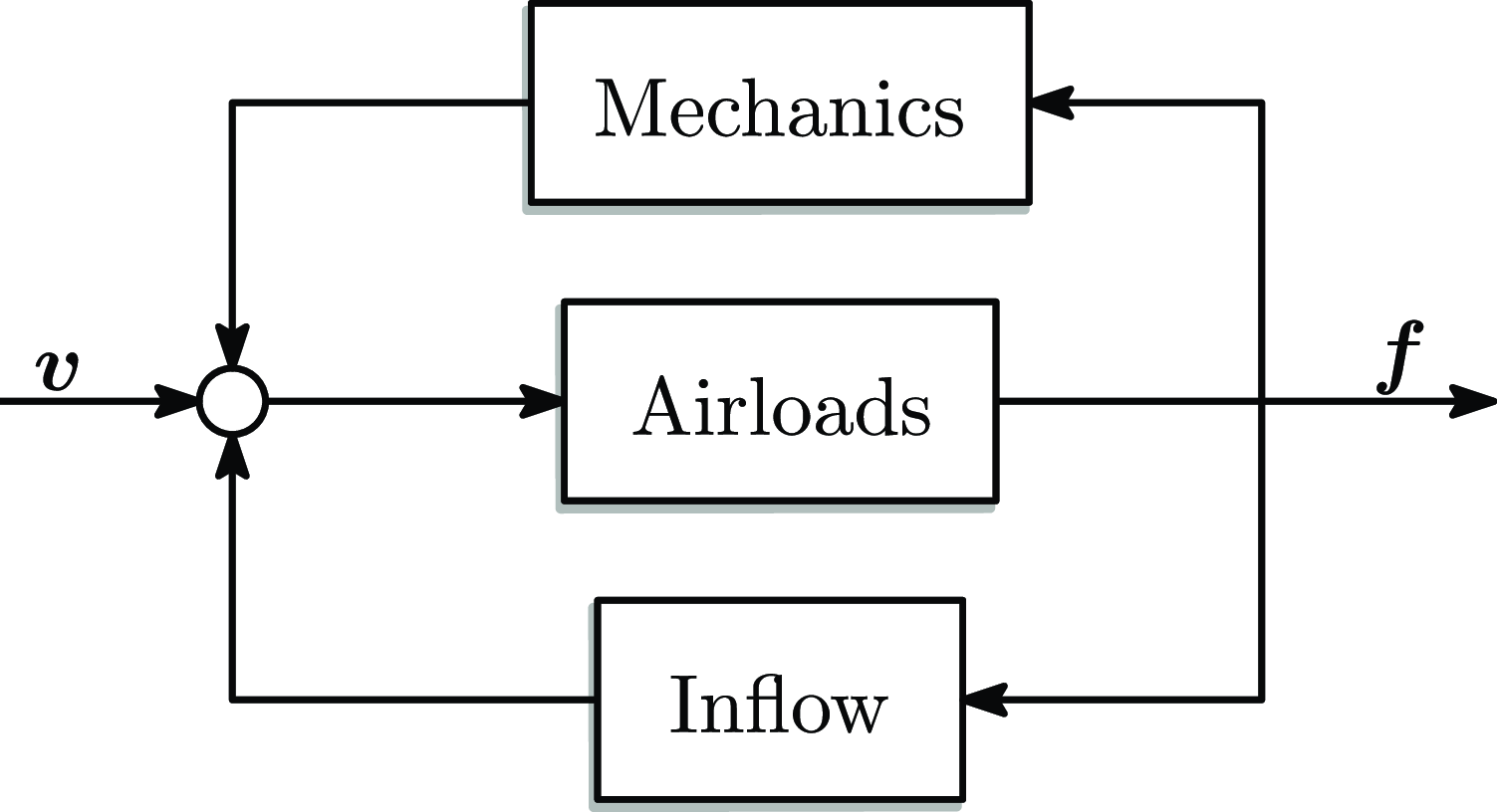


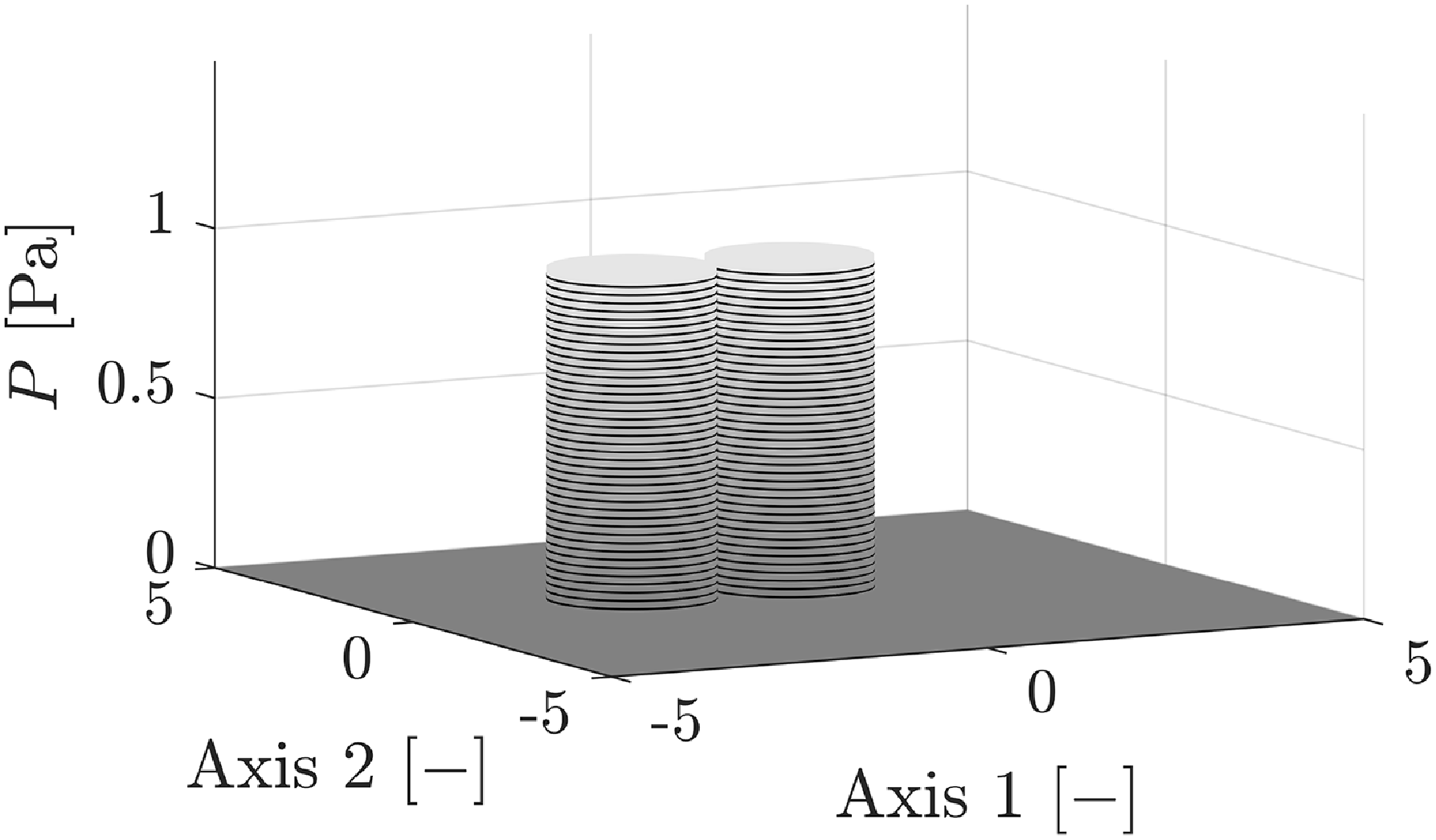
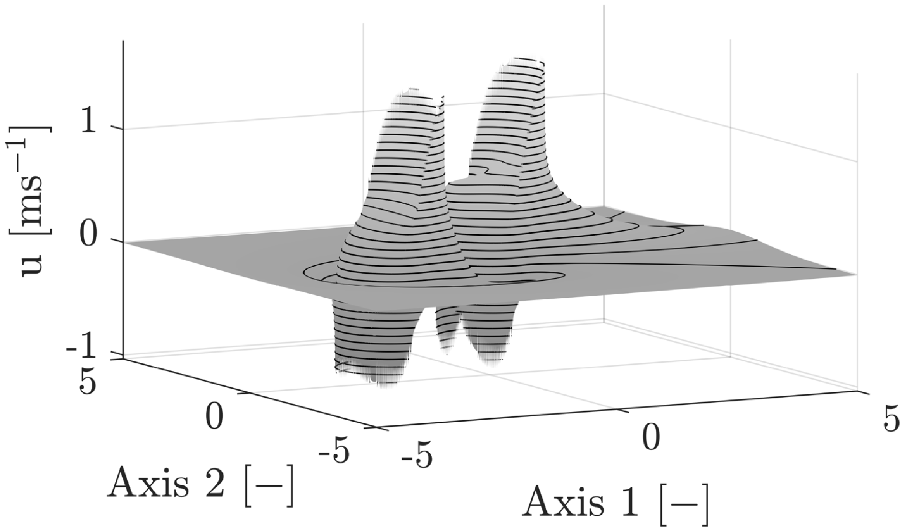


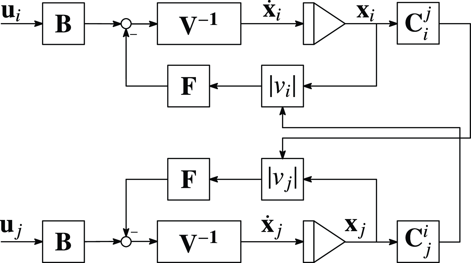


 Open access