


Impact statement
Drop shafts perform a critical role in conveying the flows from the surface to the underground, and their efficiency is critical to ensuring urban resilience against flooding. Today’s standard designs for drop shafts are based only on time-averaged flow characteristics, and the transient fluctuations have been ignored. Yet the fluctuations, if significant, can lead to choking of the air core inside the drop shaft and loss of conveyance at worst. This study employs large eddy simulations to investigate the transient flow dynamics within a drop shaft attached to a scroll vortex intake. This study provides a deeper understanding of the complex, transient phenomena in scroll vortex drop shafts, which are essential for improving the design and safety of urban drainage infrastructure.
1. Introduction
Flood prevention and water management are fundamental components of urban resilience (Lund et al. Reference Lund, Borup, Madsen, Mark, Arnbjerg-Nielsen and Mikkelsen2019; Tran et al. Reference Tran, Ivanov, Huang, Murphy, Daneshvar, Bednar, Alexander, Kim and Wright2024). Up to 18 % of the money spent to enhance urban resilience in megacities is being used in the water sector, which is currently challenged by climate change (Georgeson et al. Reference Georgeson, Maslin, Poessinouw and Howard2016). In this context, urban drainage systems play a critical role, serving as critical infrastructure for water management (Tian et al. Reference Tian, Ramsbottom, Sun, Huang, Zou and Liu2023). Among these systems, drop shafts are essential hydraulic structures in densely populated cities, facilitating the efficient conveyance of water from higher to lower elevations. Today, major cities like Tokyo, Hong Kong and Singapore increasingly rely on drop shafts as vital components of their drainage and sewerage networks.
Drop shafts equipped with vortex flow intakes offer enhanced energy dissipation by guiding water from the horizontal approach channel into a helicoidal path, forming a water layer along the shaft wall while maintaining an air core at the centre. This design prevents hydraulic choking and improves the system’s overall conveyance capacity (Mulligan et al. Reference Mulligan, Plant, Nash and Clifford2019). Since the development of the first vortex drop shaft by Drioli (Reference Drioli1947), various intake configurations have been developed, including circular, tangential, spiral and scroll vortex intakes (Jain Reference Jain1984; Hager Reference Hager1990; Yu & Lee Reference Yu and Lee2009; Mulligan et al. Reference Mulligan, Plant, Nash and Clifford2019). Over the past several decades, numerous studies have investigated the performance of these systems, particularly focusing on the complex internal vortex dynamics and air–water interactions (Drioli Reference Drioli1969; Guo Reference Guo2012; Hager Reference Hager1985; Jain Reference Jain1984, Reference Jain1987; Yu & Lee Reference Yu and Lee2009). Their performance has been further studied using the computational fluid dynamics (CFD) method in recent years (Plant & Crawford Reference Plant and Crawford2016; Zhang et al. Reference Zhang, Wang, Zhou, Dong and Zhou2018; Carty et al. Reference Carty, O’ Neill, Nash, Clifford and Mulligan2019; Chan & Qiao Reference Chan and Qiao2022; Chan Reference Chan2022; Chang & Wei Reference Chang and Wei2023; Wang et al. Reference Wang, Yu, Zhang and Law2024). These efforts have established performance criteria, with the minimum air-core percentage emerging as a critical metric (Mahmoudi-Rad & Najafzadeh Reference Mahmoudi-Rad and Najafzadeh2021). To prevent hydraulic choking, the minimum air-core area should exceed 25 % of the shaft’s cross-sectional area (Jain & Ettema Reference Jain, Ettema and Knauss1987).
While earlier research has contributed significantly to understanding the hydraulic characteristics of vortex drop shafts, most studies have focused on steady, time-averaged flow characteristics. Although these characteristics are crucial for evaluating system performance, transient flow fluctuations, which can lead to grave consequences to drainage systems such as instantaneous air core closure and choking, remain underexplored. Such scenarios, if not adequately assessed, could compromise the performance of urban drainage systems during critical events. To our knowledge, no numerical studies have addressed the unsteady flow dynamics within vortex drop shafts.
This study aims to fill this gap by conducting a comprehensive CFD investigation of a scroll vortex drop shaft. large eddy simulations (LESs) are used to examine both steady and unsteady flow characteristics for the first time. Large eddy simulation, an advanced CFD technique, is particularly adept at capturing transient phenomena and has been successfully applied in the study of vortex-dominated flows, such as streamwise vortices in aerospace, turbine applications and water treatment systems (Forster et al. Reference Forster, Diasinos, Doig and Barber2019; Shen et al. Reference Shen, Wang, Zhang and Liang2022; S. Zhang & Law Reference Zhang and Law2024). Large eddy simulation has also recently been adopted to simulate air-core vortices, which are the dominant flow phenomenon inside scroll vortex drop shafts. For instance, the vortex structures and their coherent structures of the air-core vortices have been numerically investigated using LES by Kan et al. (Reference Kan, Xu, Li, Xu, Chen, Zi, Gao and Shen2023) and Li et al. (Reference Li, Xu, Feng, Chen, Kan, Li and Shen2024), and the effects of the discharge-to-submergence ratio have been quantitatively examined by Li et al. (Reference Li, Chen, Xu, Feng, Kan, Li and Shen2023). By applying LES to the vortex drop shaft, this study provides novel insights into transient flow structures that are difficult to capture with current experimental techniques, providing a crucial foundation for improved design standards. Section 2 describes the methodology of numerical simulations, and Section 3 presents and discusses the LES predictions. Finally, a conclusion is drawn in Section 4.
2. Methodology
2.1. Design of scroll vortex drop shafts
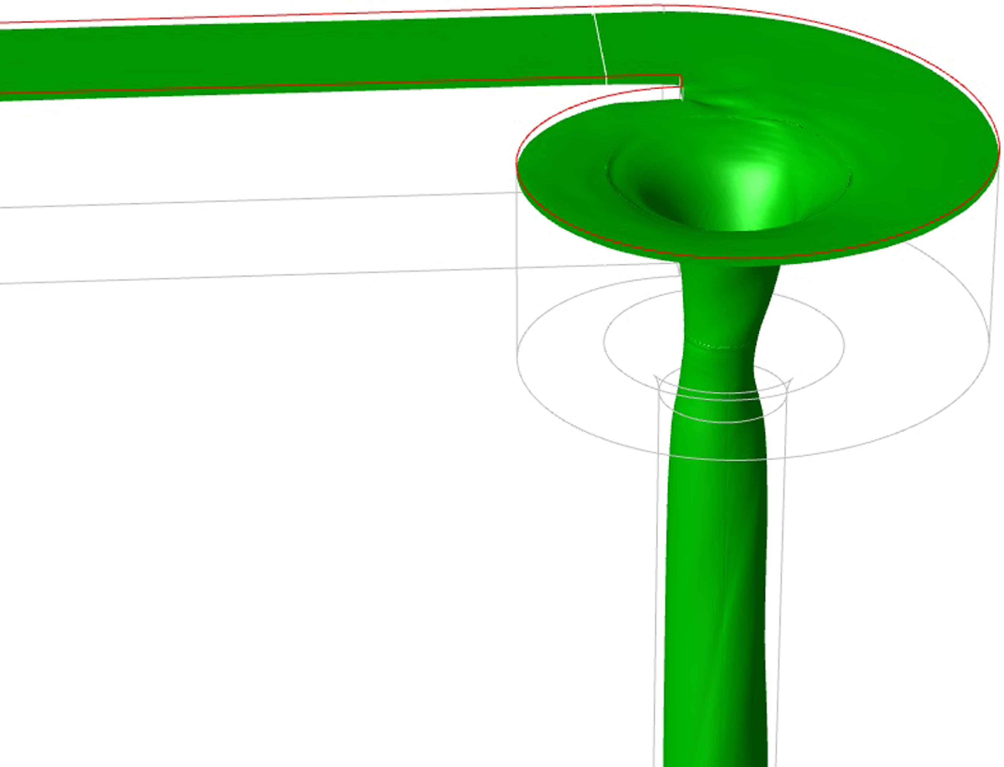
The geometrical design of scroll vortex intakes plays a crucial role in determining the hydraulic performance of drop shafts. A scroll vortex intake introduces angular momentum to the incoming flow, creating a stable air core that prevents hydraulic choking while efficiently conveying water through the drop shaft. In this study, the scroll vortex intake is designed based on Drioli’s (Reference Drioli1969) and Jain and Ettema’s (Reference Jain1987) recommendations. Figure 1 illustrates the schematic of a scroll vortex drop shaft, with key dimensions defined.
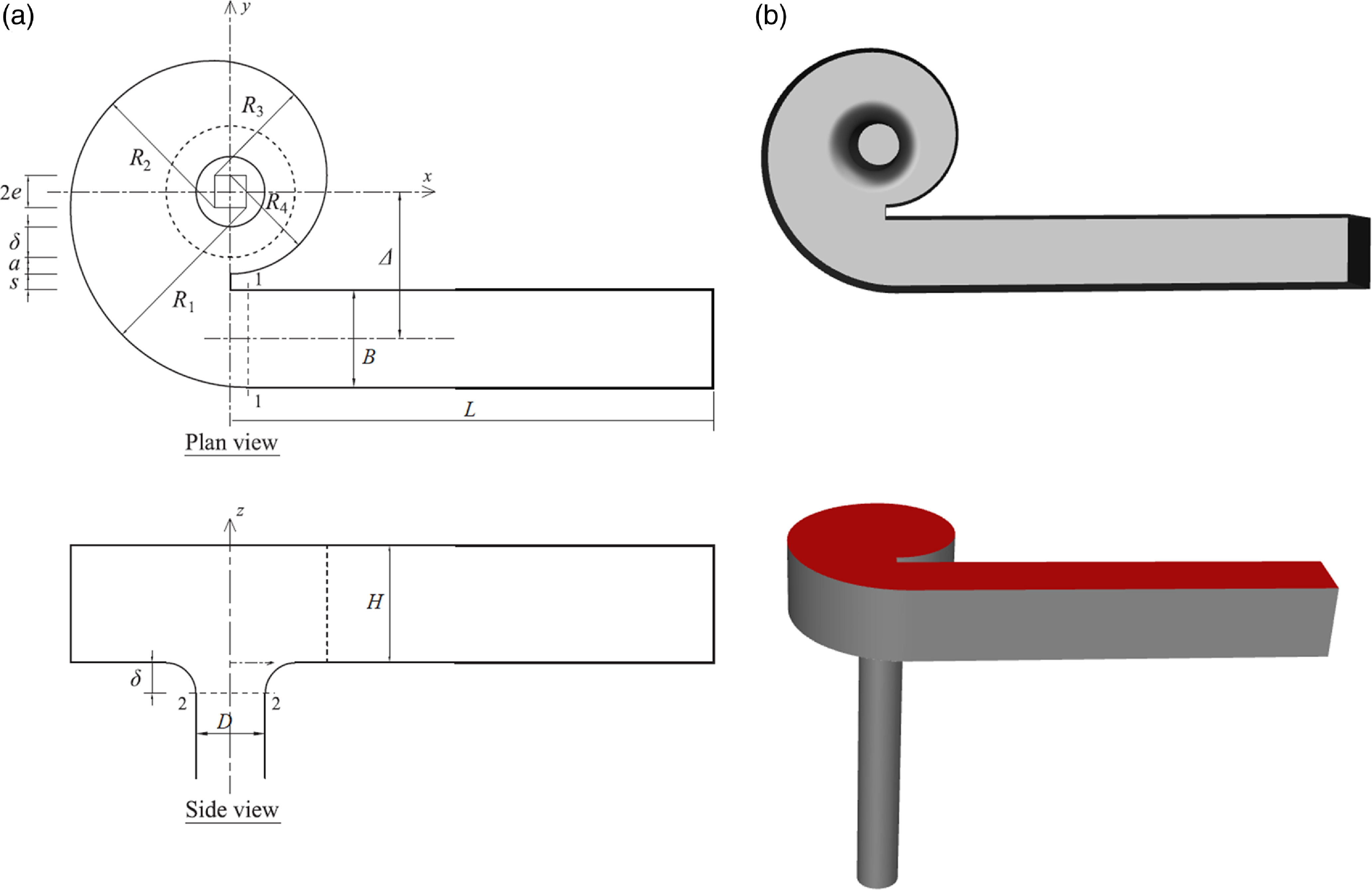
Figure 1. (a) Geometry of a scroll vortex drop shaft, and (b) three-dimensional model for numerical simulations.
The primary design feature of the scroll vortex intake is its ability to transform incoming flow from the approach channel into a vortex, forming an air core throughout the scroll chamber and drop shaft. This is achieved by offsetting the approach channel from the drop shaft’s centreline, generating angular momentum that facilitates vortex formation. The air core forms along the vertical shaft’s centre and typically reaches its minimum cross-sectional area at the bell mouth throat.
Several analytical models have been developed to describe the flow structure within scroll vortex intakes (Drioli Reference Drioli1969; Guo Reference Guo2012; Hager Reference Hager1985; Jain & Ettema Reference Jain, Ettema and Knauss1987; Pica Reference Pica1970; Viparelli Reference Viparelli1950). These models typically employ a control volume approach, analysing flow between two key cross-sections: the outlet of the approach channel (cross-section 1-1 in figure 1(a)) and the bell mouth throat (cross-section 2-2). The goal is to link the geometrical dimensions – such as the intake width, approach flow depth and drop shaft diameter – to the discharge flow rate Q and the head h a . For instance, Chan (Reference Chan2022) proposed an analytical model that estimates the values of head h a and minimum air-core percentage A mac by using the following equations:
 \begin{equation}Q=\sqrt{\frac{2gB^{2}h_{a}^{2}\left(h_{a}+\delta \right)}{\left(\frac{{\unicode[Arial]{x0394}} }{R}\right)^{2}\left(\frac{5-3\lambda _{m}}{2}\right)-1}},\end{equation}
 \begin{equation}h_{a}=\frac{C\pi }{\sqrt{2}}\left(1-\lambda _{m}\right)^{\frac{3}{2}}\left(\frac{R{\unicode[Arial]{x0394}} }{B}\right),\end{equation}
where $\lambda _{m}=A_{mac}/(\pi D^{2}/4)$
is the minimum percentage of air-core area compared with the cross-sectional area of the drop shaft, C is a coefficient and the other quantities are the geometrical dimensions shown in figure 1. Similar formulae can also be found in other models from previous studies (Drioli Reference Drioli1969; Guo Reference Guo2012; Hager Reference Hager1985; Jain & Ettema Reference Jain, Ettema and Knauss1987; Pica Reference Pica1970; Viparelli Reference Viparelli1950). These models provide valuable tools for predicting the performance of scroll vortex intakes based on geometry, enabling engineers to optimise design configurations for specific flow rates.
$\lambda _{m}=A_{mac}/(\pi D^{2}/4)$
is the minimum percentage of air-core area compared with the cross-sectional area of the drop shaft, C is a coefficient and the other quantities are the geometrical dimensions shown in figure 1. Similar formulae can also be found in other models from previous studies (Drioli Reference Drioli1969; Guo Reference Guo2012; Hager Reference Hager1985; Jain & Ettema Reference Jain, Ettema and Knauss1987; Pica Reference Pica1970; Viparelli Reference Viparelli1950). These models provide valuable tools for predicting the performance of scroll vortex intakes based on geometry, enabling engineers to optimise design configurations for specific flow rates.
Despite their utility for drop shaft designs, current design standards focus only on steady-state flow conditions. For instance, as Equations 1 and 2 illustrate, many design models design the drop shaft’s geometry using key performance metrics — particularly the specific threshold of the minimum percentage of air-core area relative to the shaft’s cross-sectional area – to prevent hydraulic choking. This threshold is based on simplified assumptions derived from quasi-steady-state analytical models or numerical simulations. In other words, these design models fail to account for transient fluctuations in the air-core shape or size, which can fluctuate significantly under variable inflow conditions. Designs that adhere strictly to steady-state criteria may underestimate the risks associated with hydraulic choking by not incorporating these fluctuations. This could compromise the overall performance and safety of the drainage system during peak flow conditions. A previous study has highlighted the need for more accurate three-dimensional numerical modelling to gain insights into transient phenomena and validate the simplifying assumptions for drop shaft designs (Guo Reference Guo2012).
2.2. Governing equations
In the present study, the flow within the scroll vortex intake is modelled using the LES-filtered Navier–Stokes equations to govern the fluid dynamics, while the volume-of-fluid method (Hirt & Nichols Reference Hirt and Nichols1981) is employed to capture the air–water interface, represented as follows:
 \begin{equation}\frac{\partial \rho }{\partial t}+\frac{\partial \left(\rho \tilde{u}_{i}\right)}{\partial x_{i}}=0,\end{equation}
 \begin{equation}\frac{\partial \left(\rho \tilde{u}_{i}\right)}{\partial t}+\frac{\partial \left(\rho \tilde{u}_{i}\tilde{u}_{j}\right)}{\partial x_{j}}=-\frac{\partial \tilde{p}}{\partial x_{i}}+\frac{\partial \sigma _{ij}}{\partial x_{i}}+\rho g_{i}-\frac{\partial \tau _{ij}}{\partial x_{i}}+F_{st,i},\end{equation}
 \begin{equation}\sigma _{ij}= \mu \left[\frac{\partial \tilde{u}_{i}}{\partial x_{j}}+\frac{\partial \tilde{u}_{j}}{\partial x_{i}}-\frac{2}{3}\frac{\partial \tilde{u}_{k}}{\partial x_{k}}\delta _{ij}\right],\end{equation}
 \begin{equation}\tau _{ij}=\rho \widetilde{{u_{i}}u_{i}}-\rho \tilde{u}_{i}\tilde{u}_{j}=-2\mu _{SGS}\tilde{S}_{ij},\end{equation}
where u
i
,u
i
represent the velocity components in the corresponding directions, t is the time, ρ is the density, p is the pressure, $g_{i}$
is the gravitational acceleration, μ is the turbulent viscosity, and
$g_{i}$
is the gravitational acceleration, μ is the turbulent viscosity, and $\mu_{{SGS}}$
is the sub-grid-scale viscosity. The over-bar of quantities denotes the LES-filtered value. The parameter
$\mu_{{SGS}}$
is the sub-grid-scale viscosity. The over-bar of quantities denotes the LES-filtered value. The parameter $\sigma _{ij}$
is the viscous stress tensor, and
$\sigma _{ij}$
is the viscous stress tensor, and $\tau _{ij}$
is the sub-grid stress tensor. The parameter
$\tau _{ij}$
is the sub-grid stress tensor. The parameter $F_{st,i}$
is the surface tension force with an expression of the continuum surface force method from (Brackbill et al. Reference Brackbill, Kothe and Zemach1992)
$F_{st,i}$
is the surface tension force with an expression of the continuum surface force method from (Brackbill et al. Reference Brackbill, Kothe and Zemach1992)
 \begin{equation}F_{st,i}= \sigma \kappa _{c}\frac{\partial \alpha }{\partial x_{i}},\end{equation}
where σ is the surface tension coefficient, κ c is the local curvature and α is the volume fraction of the water phase. The range of α is from 0 to 1, and its transport equation is expressed as
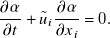 \begin{equation}\frac{\partial \alpha }{\partial t}+\tilde{u}_{i}\frac{\partial \alpha }{\partial x_{i}}=0.\end{equation}
The weight-averaged density and viscosity of mixed fluid in the air-water interface are calculated by α as follows:
 \begin{equation}\rho =\alpha \rho _{l}+\left(1-\alpha \right)\rho _{g},\end{equation}
 \begin{equation}\mu =\alpha \mu _{l}+(1-\alpha )\mu _{g}\end{equation}
where the subscript l denotes the liquid phase and g is the gas phase. To close the above equations, a sub-grid-scale (SGS) model is required for small-scale motion (represented by $\tau _{ij}$
in Equation (6)) in the LES approach.
$\tau _{ij}$
in Equation (6)) in the LES approach.
The original SGS model, known as the Smagorinsky–Lilly model, was developed by Smagorinsky (Reference Smagorinsky1963). In this model, the SGS turbulent viscosity ( $\mu _{SGS}$
) is determined by the filtered strain rate tensor (
$\mu _{SGS}$
) is determined by the filtered strain rate tensor ( $\tilde{S}_{ij}$
), linking the velocity scale to the local strain rate. This establishes a connection between sub-grid dissipation and the strain rate at the smallest resolved scale, making it difficult for the model to accurately resolve vorticity-dominant regions as opposed to strain-dominant areas (Forster et al. Reference Forster, Diasinos, Doig and Barber2019). Furthermore, in wall-bounded scenarios, the Smagorinsky constant in the Smagorinsky–Lilly model needs to be adjusted at the wall to ensure that the value of
$\tilde{S}_{ij}$
), linking the velocity scale to the local strain rate. This establishes a connection between sub-grid dissipation and the strain rate at the smallest resolved scale, making it difficult for the model to accurately resolve vorticity-dominant regions as opposed to strain-dominant areas (Forster et al. Reference Forster, Diasinos, Doig and Barber2019). Furthermore, in wall-bounded scenarios, the Smagorinsky constant in the Smagorinsky–Lilly model needs to be adjusted at the wall to ensure that the value of $\mu _{SGS}$
approaches zero at the wall. In contrast, the wall-adapting local eddy-viscosity (WALE) SGS model was introduced to address the near-wall scaling effect on the velocity scale and eddy viscosity (Nicoud & Ducros Reference Nicoud and Ducros1999). Studies have shown that the WALE model outperforms other SGS models in scenarios involving wall boundaries and vortex problems (Forster et al. Reference Forster, Diasinos, Doig and Barber2019; Ma et al. Reference Ma, Wang and Tang2009; Yilmaz & Davidson Reference Yilmaz and Davidson2015). Therefore, the WALE model is chosen for this study to simulate the complex flow in the scroll vortex intake, including both wall boundary and vortex-dominant flow.
$\mu _{SGS}$
approaches zero at the wall. In contrast, the wall-adapting local eddy-viscosity (WALE) SGS model was introduced to address the near-wall scaling effect on the velocity scale and eddy viscosity (Nicoud & Ducros Reference Nicoud and Ducros1999). Studies have shown that the WALE model outperforms other SGS models in scenarios involving wall boundaries and vortex problems (Forster et al. Reference Forster, Diasinos, Doig and Barber2019; Ma et al. Reference Ma, Wang and Tang2009; Yilmaz & Davidson Reference Yilmaz and Davidson2015). Therefore, the WALE model is chosen for this study to simulate the complex flow in the scroll vortex intake, including both wall boundary and vortex-dominant flow.
The formula for the SGS turbulent viscosity in the WALE model is as follows:
 \begin{equation} \mu _{SGS}=\rho \left(C_{w}{\unicode[Arial]{x0394}} \right)^{2}\frac{\left(S_{ij}^{d}S_{ij}^{d}\right)^{3/2}}{{\left(\tilde{S}_{ij}\tilde{S}_{ij}\right)^{5/2}}+\left(S_{ij}^{d}S_{ij}^{d}\right)^{5/4}}\tilde{S}_{ij}\end{equation}
where $C_{w}$
is the WALE constant,
$C_{w}$
is the WALE constant, $\Delta$
is the characteristic sub-grid length scale and
$\Delta$
is the characteristic sub-grid length scale and $S_{ij}^{d}$
is the traceless symmetric part of the square of the velocity gradient tensor. In this study, the WALE constant is set to
$S_{ij}^{d}$
is the traceless symmetric part of the square of the velocity gradient tensor. In this study, the WALE constant is set to $C_{w}=0.325$
(Forster et al. Reference Forster, Diasinos, Doig and Barber2019; Lehmkuhl et al. Reference Lehmkuhl, Rodríguez, Baez, Oliva and Pérez-Segarra2013).
$C_{w}=0.325$
(Forster et al. Reference Forster, Diasinos, Doig and Barber2019; Lehmkuhl et al. Reference Lehmkuhl, Rodríguez, Baez, Oliva and Pérez-Segarra2013).
The above governing equations are solved in ANSYS Fluent version 2021, a popular commercial solver based on the finite volume method. The SIMPLEC (semi-implicit method for pressure linked equations-consistent) algorithm, a modified form of the semi-implicit method for pressure-linked equations (SIMPLE) algorithm, is employed to find the solution to the system of governing equations. The convection terms in the momentum equations are discretised using the second-order central scheme. The convection of volume fraction is solved using the compressive scheme with a slope limiter. The face value of pressure is interpolated using the PREssure STaggering Option (PRESTO!) scheme (Patankar Reference Patankar2018). The gradient terms are computed using the least squares cell-based gradient evaluation. The convergence criteria for the quantities of the continuity, velocities and the volume of fraction for water are all set to 10−6.
2.3. Numerical set-up
The numerical configuration in the present study is based on the dimensions of a physical model from Guo (Reference Guo2012), and the two-phase (air and water) computational model is shown in figure 1(b). The specific geometric parameters are summarised in supplementary table 1. A velocity inlet boundary condition is set to the inflow boundary for the phase of water. For all simulations, we set the initial water level at the inlet boundary to the value based on the measured approach head h a at Q = 10 l/s from Guo (Reference Guo2012). The top boundary from the approach channel to the vortex chamber is set as a pressure inlet. The bottom of the vertical drop shaft is set as a pressure outlet, and all the wall boundaries are defined as a no-slip boundary condition. A random flow generation (RFG) algorithm originally proposed by Kraichnan (Reference Kraichnan1970) and developed by Smirnov et al. (Reference Smirnov, Shi and Celik2001) is adopted to generate fluctuating velocity components at the inlet boundary. To initiate RFG, a turbulence intensity of 15 % and the corresponding hydraulic diameter at each flow rate are set to the inlet boundary.
The mesh is generated by the mesh generator ANSYS ICEM for the entire numerical domain, as shown in figure 2. The computational domain is divided into three mesh zones with different schemes to adopt the most structured mesh for the complex irregular configuration. A structured hexahedral grid is applied to the approach channel, and a structured hexahedral grid with the O-grid scheme is applied to the drop shaft, bell mouth and the scroll chamber’s core region extruded from the bell mouth’s outer circle. The outer part of the scroll chamber is swept along the vertical direction by unstructured quadrilateral-dominant meshes on the top and bottom surfaces. The structured grid in the approach channel comprises 110, 40 and 50 nodes in the x, y and z directions, respectively. In the drop shaft and bell mouth, the O-grid consists of 160 × 25 × 146 nodes in the tangential, radial (for the outer region of the O-grid) and axial directions, respectively. The node count in the inner region of the scroll chamber matches that of the drop shaft in the tangential and radial directions while aligning with the outer region in the axial direction. Moving to the outer region of the scroll chamber, there are 330 nodes in the tangential direction, 40 to 55 nodes in the radial direction and 50 nodes in the axial direction. The node count in the inner region of the scroll chamber matches that of the drop shaft in the tangential and radial directions while aligning with the outer region in the axial direction. This set-up results in a minimum grid size of 0.5 mm in the drop shaft and a maximum axial length of 8 mm at the outlet boundary. Furthermore, finer grids with smooth expansion ratios are implemented in the near-wall region to ensure a first cell layer thickness of y+ = 1.
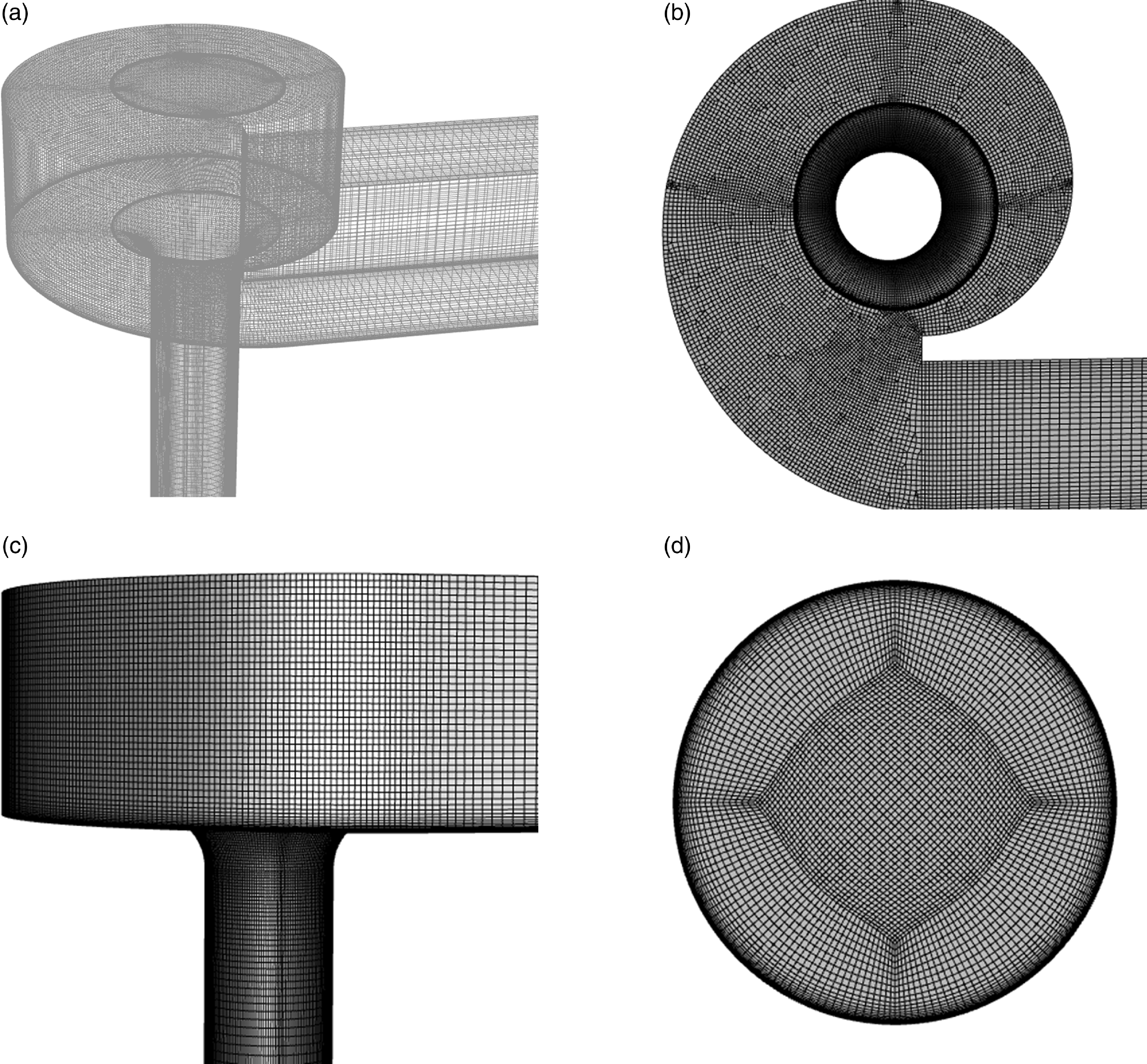
Figure 2. Grid mesh: (a) transparent overview, (b) top view, (c) side view and (d) O-grid outlet.
Four cases at different flow rates are simulated in the present study, as shown in supplementary table 2. The gas (air) and liquid (water) phases are defined as an ideal gas and an incompressible liquid, respectively. Gravity is defined as a driven force with an acceleration of −9.81 m2/s in the z-axis direction. The time-averaged results are computed for an additional 10–15 s after the flow time exceeds 20 s, to ensure that the effects due to the initial conditions have been fully removed. Furthermore, based on the temporal analysis of the air-core variation, the Nyquist frequency of ∼ 1/5 Hz within the duration of the analysis is well below the peak frequency of 0.78 Hz for the peak spectral density, which will be indicated later in Section 3.2.
3. Results and discussion
3.1. Model validation
It is essential to first validate the LES results by comparing them with suitable experimental data, given the assumptions in LES sub-grid models. In this study, the LES results are compared with the experimental data from Guo (Reference Guo2012), including the time-averaged head-discharge relationship and air-core percentage.
3.1.1 Head-discharge relationship
The head-discharge relationship, i.e. the correlation between the water height in the approach channel and the flow rate, has been extensively studied for scroll vortex drop shafts in the literature (Drioli Reference Drioli1969; Pica Reference Pica1970; Viparelli Reference Viparelli1950). Guo (Reference Guo2012) performed a comprehensive experimental study investigating the head-discharge relationship as well as the air-core percentage at flow rates Q = 1 ∼ 10 l/s. Figure 3(a) shows the relationship between the non-dimensional water head $h_{a}/D$
and the non-dimensional flow rate
$h_{a}/D$
and the non-dimensional flow rate $Q/\sqrt{gD^{5}}$
. Two CFD predictions based on Reynolds-averaged Navier-Stokes (RANS) models from Chan (Reference Chan2022) and Wang et al. (Reference Wang, Yu and Law2023) are also included for comparison of the water head. It is observed from the experimental data that there is a linear correlation between the non-dimensional water head and flow rate within the measured range. The LES predictions show the best agreement with the experimental data compared with the other two CFD predictions.
$Q/\sqrt{gD^{5}}$
. Two CFD predictions based on Reynolds-averaged Navier-Stokes (RANS) models from Chan (Reference Chan2022) and Wang et al. (Reference Wang, Yu and Law2023) are also included for comparison of the water head. It is observed from the experimental data that there is a linear correlation between the non-dimensional water head and flow rate within the measured range. The LES predictions show the best agreement with the experimental data compared with the other two CFD predictions.
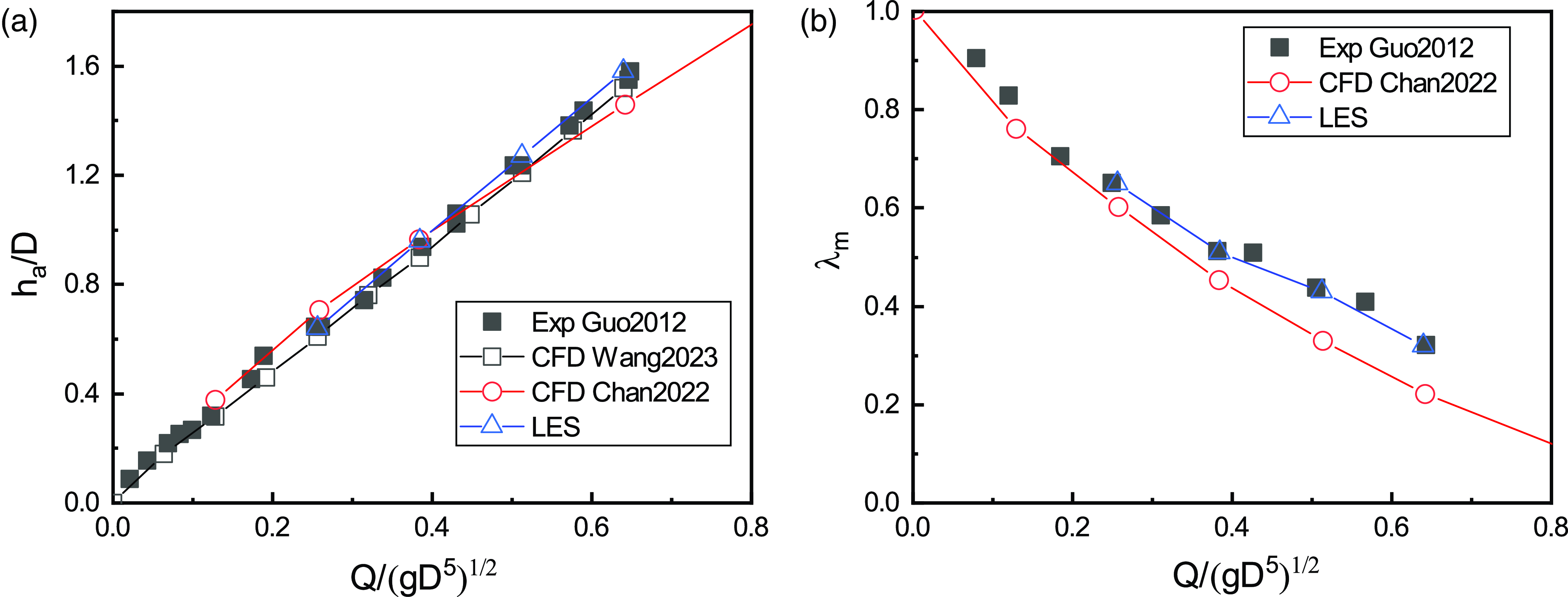
Figure 3. (a) Head-discharge relationship and (b) percentage of minimum air-core versus flow rates.
3.1.2 Air-core percentage
The experimental investigation of air core in drop shafts remains challenging, and only limited studies had been conducted over the past decades (Guo Reference Guo2012; Jain & Ettema Reference Jain, Ettema and Knauss1987). Figure 3(b) presents the relationship between the minimum air-core percentage $\lambda _{m}$
and the non-dimensional flow rate
$\lambda _{m}$
and the non-dimensional flow rate $Q/\sqrt{gD^{5}}$
in comparison with the experimental data from Guo (Reference Guo2012). The LES predictions from the figure fit well with the experimental data, whereas the previous CFD results somewhat under-predict the
$Q/\sqrt{gD^{5}}$
in comparison with the experimental data from Guo (Reference Guo2012). The LES predictions from the figure fit well with the experimental data, whereas the previous CFD results somewhat under-predict the $\lambda _{m}$
, especially at higher flow rates.
$\lambda _{m}$
, especially at higher flow rates.
3.2. Transient evolution of air core
A key objective of this study is to investigate the transient evolution of the air core, which is theoretically impossible for conventional RANS models without transient components (e.g. $k-\varepsilon$
or
$k-\varepsilon$
or $k-\omega$
model) and challenging for experimentation due to the lack of experimental techniques to capture the transient water–air interface with satisfactory accuracy (Chanson Reference Chanson2002; Felder & Chanson Reference Felder and Chanson2015; Guo Reference Guo2012).
$k-\omega$
model) and challenging for experimentation due to the lack of experimental techniques to capture the transient water–air interface with satisfactory accuracy (Chanson Reference Chanson2002; Felder & Chanson Reference Felder and Chanson2015; Guo Reference Guo2012).
The cross-sectional shape of the air core at z = −30 mm inside the bell mouth is analysed to gain insights into its fluctuation inside the drop shaft. Figure 4 shows the transient evolution at a time interval of 0.5s, where the red and blue colours represent the air and water phases, respectively. From the figure, the non-axisymmetry of the transient air-core shape can be observed to be significantly higher, and its curvilinearity is more complex than that of the time-averaged shape. The transient evolution of the air-core percentage λ is also plotted at different cross-sections in figure 5(a) which show high fluctuations along the drop shaft. Quantitatively, the variations of the minimum air-core percentage, $\lambda _{m}$
, around its mean value are observed to be within −13.2 % ∼ 8.6 % (a total range of 21.8 %) in this study. The time series of air-core size is further analysed using fast Fourier transform to gain insights into the inherent frequency of the transient fluctuations, as shown in figure 5(b). The peak value of power spectral density (PSD) occurs at the frequency of 0.78 Hz (corresponding to the period of 1.28 s), which can be regarded as the dominant frequency (period). It should be noted that this peak PSD for air-core percentage fluctuation would be dependent on the drop shaft geometry, and a lower frequency can be expected for a full-size drop shaft.
$\lambda _{m}$
, around its mean value are observed to be within −13.2 % ∼ 8.6 % (a total range of 21.8 %) in this study. The time series of air-core size is further analysed using fast Fourier transform to gain insights into the inherent frequency of the transient fluctuations, as shown in figure 5(b). The peak value of power spectral density (PSD) occurs at the frequency of 0.78 Hz (corresponding to the period of 1.28 s), which can be regarded as the dominant frequency (period). It should be noted that this peak PSD for air-core percentage fluctuation would be dependent on the drop shaft geometry, and a lower frequency can be expected for a full-size drop shaft.
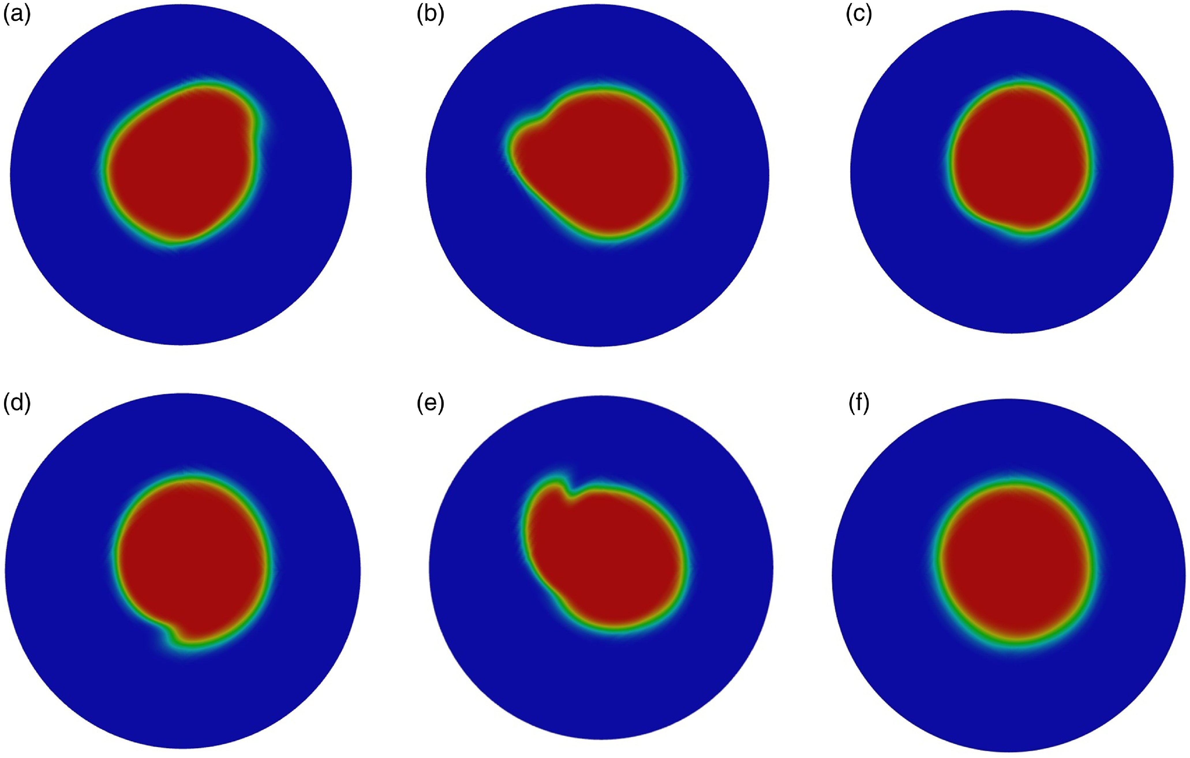
Figure 4. Transient evolution of air core in the bell mouth (z = 30 mm) for Q = 10 l/s: (a)–(e) $\Delta$
t = 0 ∼ 2 s, (f) time averaged.
$\Delta$
t = 0 ∼ 2 s, (f) time averaged.
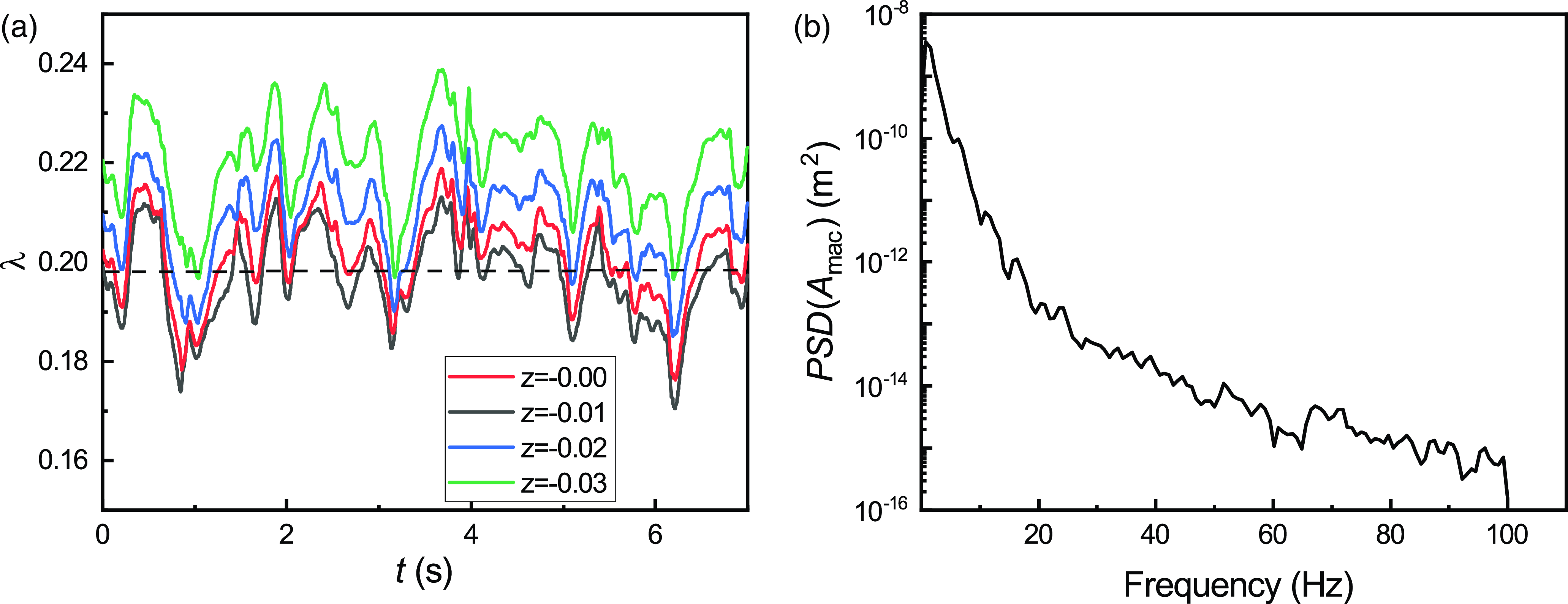
Figure 5. (a) Temporal variation of air-core percentage at different cross-sections and (b) PSD of the minimum air-core size for Q = 15 l/s.
The fluctuation of air-core percentage can have significant implications to the design of scroll vortex drop shaft. Jain & Ettema (Reference Jain, Ettema and Knauss1987) recommended that the time-averaged minimum air-core size should exceed 25 % to prevent choking inside the drop shaft. This criterion provides a safe margin against possible variations due to the influences of the intake’s geometry, flow rate, approach flow disturbances and other factors. For example, Del Giudice et al. (Reference Del Giudice, Gisonni and Rasulo2010) showed that the air core can be reduced by 20 % due to the occurrence of a hydraulic jump in the approach flow. The recommendation by Jain & Ettema (Reference Jain, Ettema and Knauss1987) is now a de facto standard and has been widely adopted successfully in the design of scroll vortex drop shafts in the industry.
In actual constructions of scroll vortex drop shafts, there can be deviations to their design geometry due to site constraints. For example, the drop shaft diameter might be found to be slightly smaller than the design value, or the design flow rate needs to be increased by a minor percentage after the dimensions have been finalised or a combination of these factors. In such situations, the minimum air-core percentage might now be less than the design buffer of 25 %. Judgment is then needed to determine whether the reduction in safety buffer remains acceptable for the field configuration, and additional CFD simulations are often conducted in these cases. Currently, it is the authors’ experience that these CFD simulations for scroll vortex drop shafts are entirely based on the steady-state RANS approach in the industry nowadays. While the steady-state RANS simulation results provide an estimate of the reduction from the 25 % value, say to 20 % for example, similar assessment should also be performed to address the transient fluctuations, i.e. whether the range of fluctuations in the air-core percentage has also increased due to the changes in the field configuration. In other words, the overall assessment can only be made by considering both the reduction in time-average value as well as the increase in the fluctuation range, which has not been done in the industry at the moment. We sincerely hope that the present study can help highlight the critical need for transient modelling to address the temporal fluctuations in the air-core percentages in these CFD simulations for scroll vortex drop shafts going forward.
3.3. Vortex structure and energy spectrum
It is important to investigate the vortex structure of water flow within the scroll chamber, bell mouth and drop shaft. The streamlines of water discharged from the inlet of the approach channel are shown in figure 6, where they show the planar swirling in the scroll chamber away from the air core at the centre and three-dimensional swirling in the drop shaft. To further visualise the vortex structure, a free surface of flowing water is plotted in figure 7 by extracting the iso-surface of an air fraction of 50 %, where the throat is observed within the bell mouth.
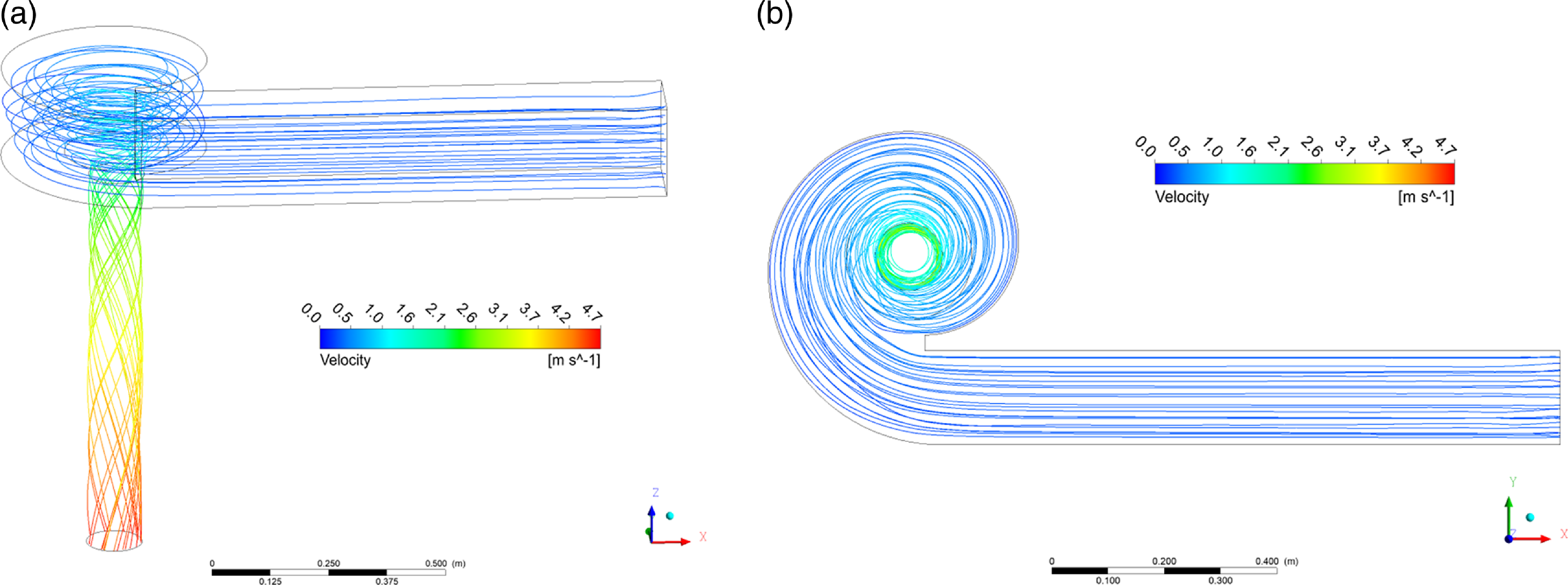
Figure 6. Streamline: (a) side view (b) top view.
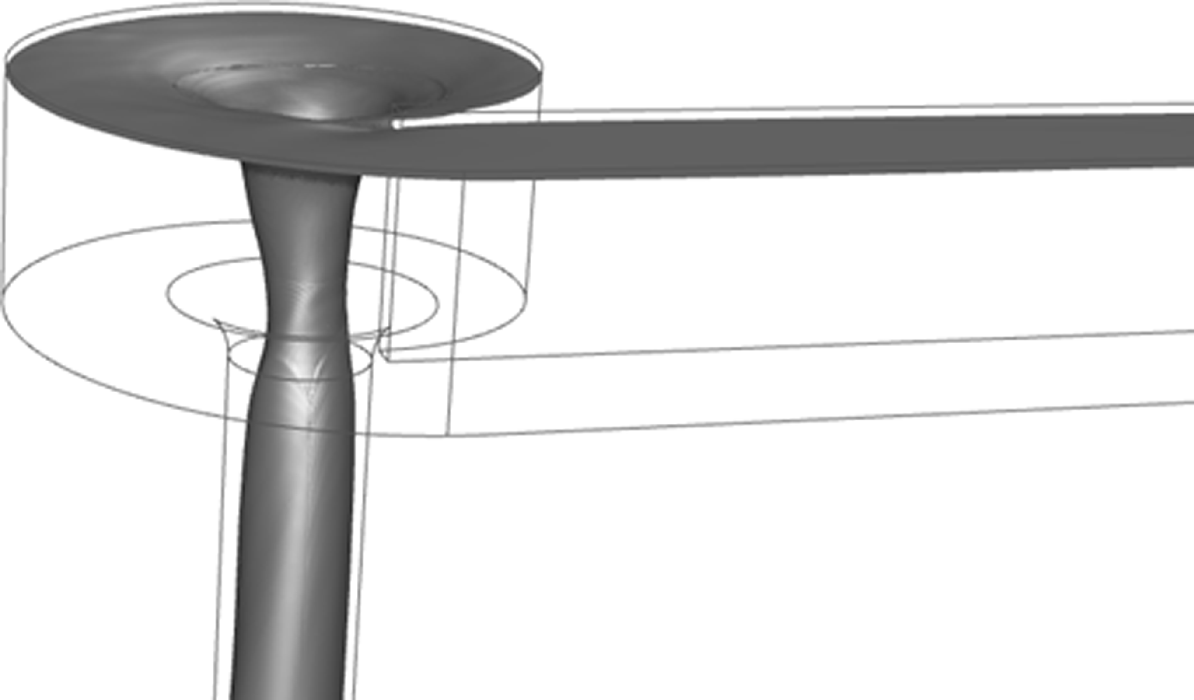
Figure 7. Free surface (iso-surface of air phase = 0.5) of flowing water.
Quantifying the vortex structure within the drop shaft is necessary for deeper insights into the transient fluctuations. The quantification for vortex identification has been a long-standing issue, even though vorticity has been defined as an elemental quantity for vortex-dominant flows for centuries. Vorticity values alone have been demonstrated to be insufficient for vortex identification as they tend to represent local quantity rather than global rotation (Jeong & Hussain Reference Jeong and Hussain1995). Hence, a few improved methods have been developed for global vortex identification (Hunt et al. Reference Hunt, Wray and Moin1988). In this study, the recently developed $\Omega$
criterion (Liu et al. Reference Liu, Wang, Yang and Duan2016) is adopted, where the vortex is identified as follows:
$\Omega$
criterion (Liu et al. Reference Liu, Wang, Yang and Duan2016) is adopted, where the vortex is identified as follows:
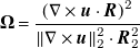 \begin{equation}\boldsymbol{\Omega }=\frac{\left(\nabla \times \boldsymbol{u}\cdot \boldsymbol{R}\right)^{2}}{\left\| \nabla \times \boldsymbol{u}\right\| _{2}^{2}\cdot \boldsymbol{R}_{2}^{2}}\end{equation}
where R is the rotational vorticity.
Figure 8 compares the vortex identification at three different $\Omega$
values from LES simulations and previous CFD simulations by Wang et al. (Reference Wang, Yu, Zhang and Law2024). From the figure, a large global vortex is observed throughout the centre of the scroll chamber and drop shaft. However, the LES predicts more smaller vortices around the central global vortex, revealing the existence of localised vortices of medium sizes that the
$\Omega$
values from LES simulations and previous CFD simulations by Wang et al. (Reference Wang, Yu, Zhang and Law2024). From the figure, a large global vortex is observed throughout the centre of the scroll chamber and drop shaft. However, the LES predicts more smaller vortices around the central global vortex, revealing the existence of localised vortices of medium sizes that the $\Omega$
criterion can identify. Among the three different
$\Omega$
criterion can identify. Among the three different $\Omega$
values, the LES prediction at
$\Omega$
values, the LES prediction at $\Omega$
= 0.52 which is recommended by Liu et al. (Reference Liu, Wang, Yang and Duan2016), shows stronger and more massive vortices in the wake region behind the scroll chamber tongue. Such a cluster of vortices becomes sparse with increased
$\Omega$
= 0.52 which is recommended by Liu et al. (Reference Liu, Wang, Yang and Duan2016), shows stronger and more massive vortices in the wake region behind the scroll chamber tongue. Such a cluster of vortices becomes sparse with increased $\Omega$
. In comparison, the global central vortex remains dominant at the highest
$\Omega$
. In comparison, the global central vortex remains dominant at the highest $\Omega$
value of 0.8.
$\Omega$
value of 0.8.
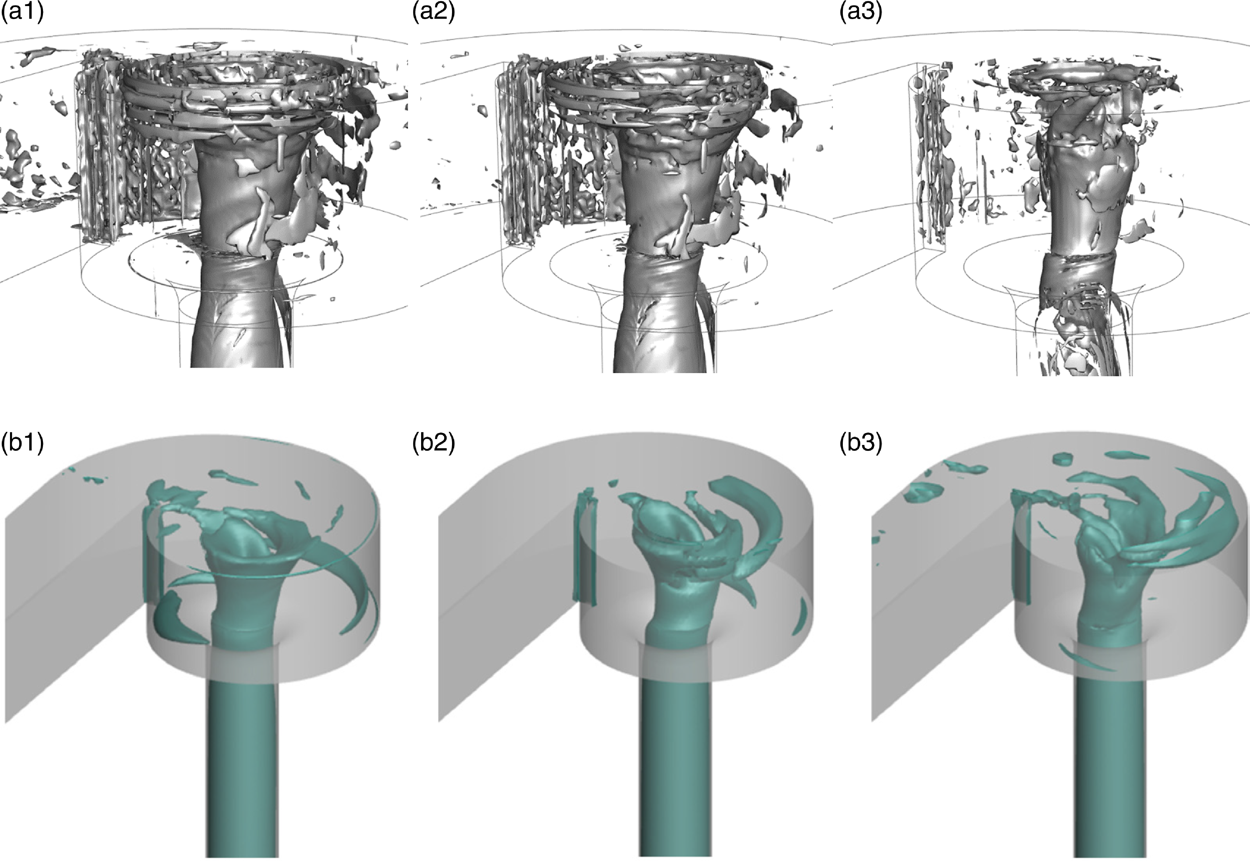
Figure 8. $\Omega$
criterion of swirling water in the scroll chamber: (a) LES results (
$\Omega$
criterion of swirling water in the scroll chamber: (a) LES results ( $\Omega$
= 0.52, 0.6, 0.8 for a.1, a.2 and a.3, respectively.) and (b) RANS (
$\Omega$
= 0.52, 0.6, 0.8 for a.1, a.2 and a.3, respectively.) and (b) RANS ( $\Omega$
= 0.52), from Wang et al. (Reference Wang, Yu, Zhang and Law2024).
$\Omega$
= 0.52), from Wang et al. (Reference Wang, Yu, Zhang and Law2024).
Figure 8 shows the large eddies predicted by the LES simulations, illustrating the spectral complexity of the flow separation-induced turbulence in the wake region behind the chamber tongue. These transient large eddies are substantially more complex than the steady-state circulations predicted by the RANS results, as expected. Particularly, their visualisation is essential towards enhancement in the understanding of instantaneous flow interactions and air-core vortex fluctuations inside the drop shaft, such as the occurrence of choking in extreme cases. Supplementary figure 2(b) shows an abrupt velocity drop at the chamber tongue at 180 degrees to a smooth velocity profile at 90 degrees, which the swirling together helps form a stable air-core vortex in the middle of the drop shaft. In the literature, it has been well demonstrated that LES can simulate the flow separation more accurately than RANS. For example, Zhang & Law (Reference Zhang and Law2024) showed that LES can predict the flow separation around circular cylinders and the wake flow pattern behind much more accurately than RANS models by comparing with experimental measurements using particle image velocimetry. Thus, it can also be expected that LES can provide better predictions of the air-core percentages comparatively. This also helps explain the under-estimations of air-core percentages from RANS simulations in figure 3(b), due to the reduced accuracy in reproducing the velocity transition in the wake region resulting in slower formation of a stable air-core vortex.
The energy spectrum is an accessible method in LES to investigate the energy distribution over the eddy-scale range, and it is computed in this study based on the velocity and its corresponding fluctuation, as shown in figure 9, where κ = 2π/L v represents the wavenumber. Large-scale motion (smaller κ number) carries the dominant eddies with high energy, and the energy spectrum shows a decline with decreased length scale (larger κ number). In a specific scale range (κ = 5 ∼ 100), the slope of the energy spectrum follows the inertial range as described in Kolmogorov (Reference Kolmogorov1941). In addition, the slope of the energy spectrum in the scroll chamber is found to be steeper than that in the drop shaft (3.2 and 1.9 for the scroll chamber and drop shaft, respectively). A lower slope indicates a trend of three-dimensional (3-D) turbulent flows in the drop shaft (Kolmogorov Reference Kolmogorov1941), attributed to the 3-D swirling motion when water flow passes through the shaft. Conversely, a higher slope reveals that the water flow in the scroll chamber preserved 2-D turbulence, where the energy in small scales is transferred to large scales by the so-called inverse energy cascade (Kraichnan Reference Kraichnan1967). Constrained by the scroll chamber wall, the majority of flow in the scroll chamber follows a planar swirling motion, forming the global vortex shown in figure 8. This accounts for the inverse energy cascade, where energy is transferred from small eddies to large eddies in the development of the global vortex.
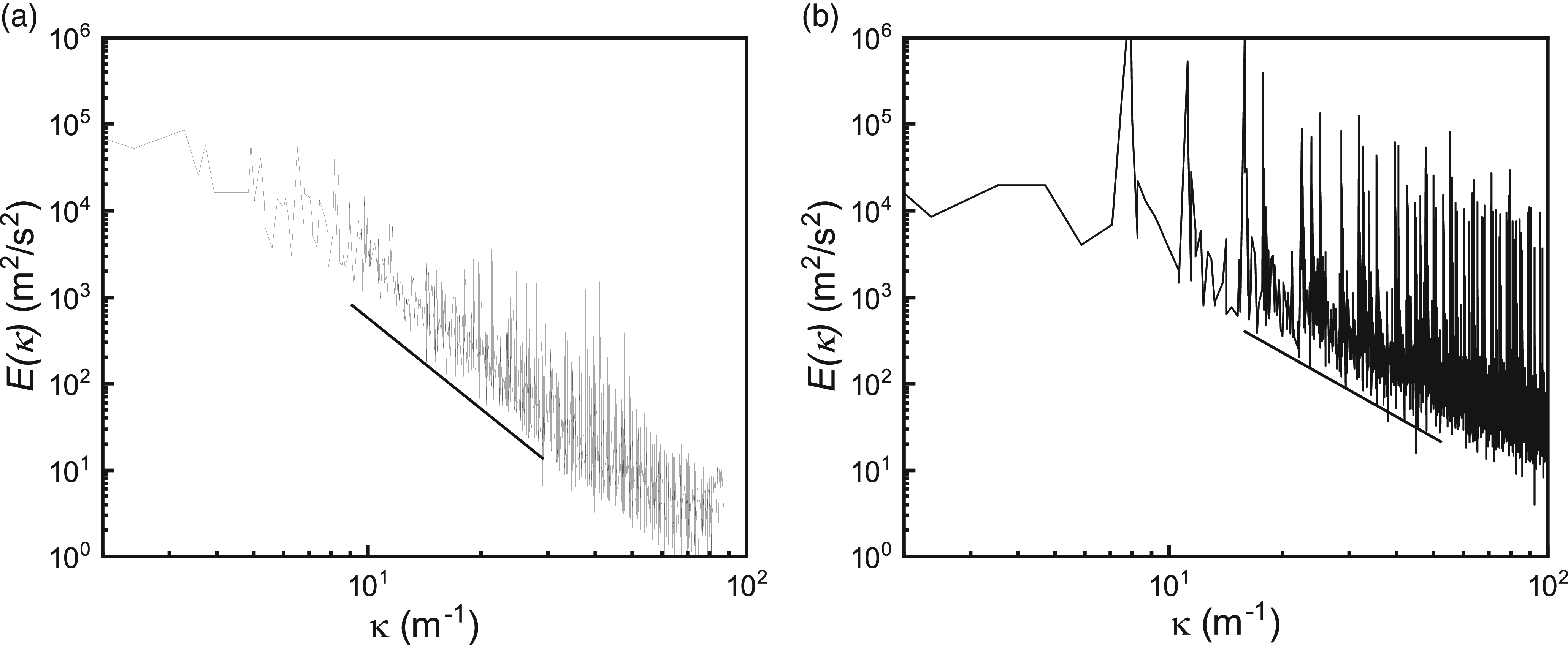
Figure 9. Energy spectrum in (a) the scroll chamber and (b) drop shaft.
3.4. Discussion on assumptions in analytical models
Existing analytical models for scroll vortex drop shafts typically rely on simplifying assumptions to predict hydraulic performance. While helpful in deriving practical design equations, these assumptions may not fully capture the complexity of the flow dynamics observed in natural systems. The key assumptions commonly made in such models (Chan Reference Chan2022; Drioli Reference Drioli1969; Guo Reference Guo2012; Jain & Ettema Reference Jain, Ettema and Knauss1987) are:
-
a. Symmetry and non-rotating flow: it is often assumed that the flow within the drop shaft is symmetric and non-rotating about the shaft axis. However, the LES-predicted velocity distributions obtained in this study challenge this assumption (see velocity distributions in the supplementary information section). As shown in supplementary figure 3, significant asymmetries in tangential velocity distributions are observed between different angular positions. Supplementary figure 4 further reveals asymmetries in vertical velocity distributions between different vertical and angular positions. These asymmetries indicate that the flow within the drop shaft is not symmetric, especially at locations near the chamber tongue and air core. The diversified velocity distribution suggests that more complex vortex structures, influenced by both geometry and inflow conditions, dominate the flow behaviour.
-
b. Radial velocity: a frequent assumption is that radial velocity components near the air-core throat are negligible compared with tangential and vertical velocities. However, the radial velocity profiles presented in figure 10(d) demonstrate that radial velocity near the throat can reach up to 0.3 m/s, which is not negligible compared with tangential and vertical velocities. This finding suggests that radial velocity components may play a more significant role in the overall flow dynamics than previously thought, particularly in regions of high velocity gradients or near sharp geometric features like the bell mouth.
-
c. Total energy head: another common assumption is that the total energy head E remains constant throughout the drop shaft, implying negligible energy dissipation. However, the radial distribution of the energy head, as shown in figure 10(a), reveals that this assumption is not valid across all regions of the flow field. The mass-integral-averaged energy head $E_{\textit{MI}}$
, plotted in figure 10(b), indicates that the energy dissipation is relatively low (approximately 3 %) in the throat region, but increases to 30 % near the outlet of the drop shaft. This highlights the significant energy losses in certain parts of the system, which should be accounted for in future designs.
$E_{\textit{MI}}$
, plotted in figure 10(b), indicates that the energy dissipation is relatively low (approximately 3 %) in the throat region, but increases to 30 % near the outlet of the drop shaft. This highlights the significant energy losses in certain parts of the system, which should be accounted for in future designs. -
d. Atmospheric pressure: analytical models also assume that the pressure inside the air core remains at atmospheric levels. The LES results presented in figure 10(c) show that this assumption is reasonably accurate for the current configuration, as the pressure remains relatively constant along the central axis of the air core. However, deviations from this assumption may occur under different operational conditions or geometrical configurations, especially when transient flow fluctuations are more pronounced.

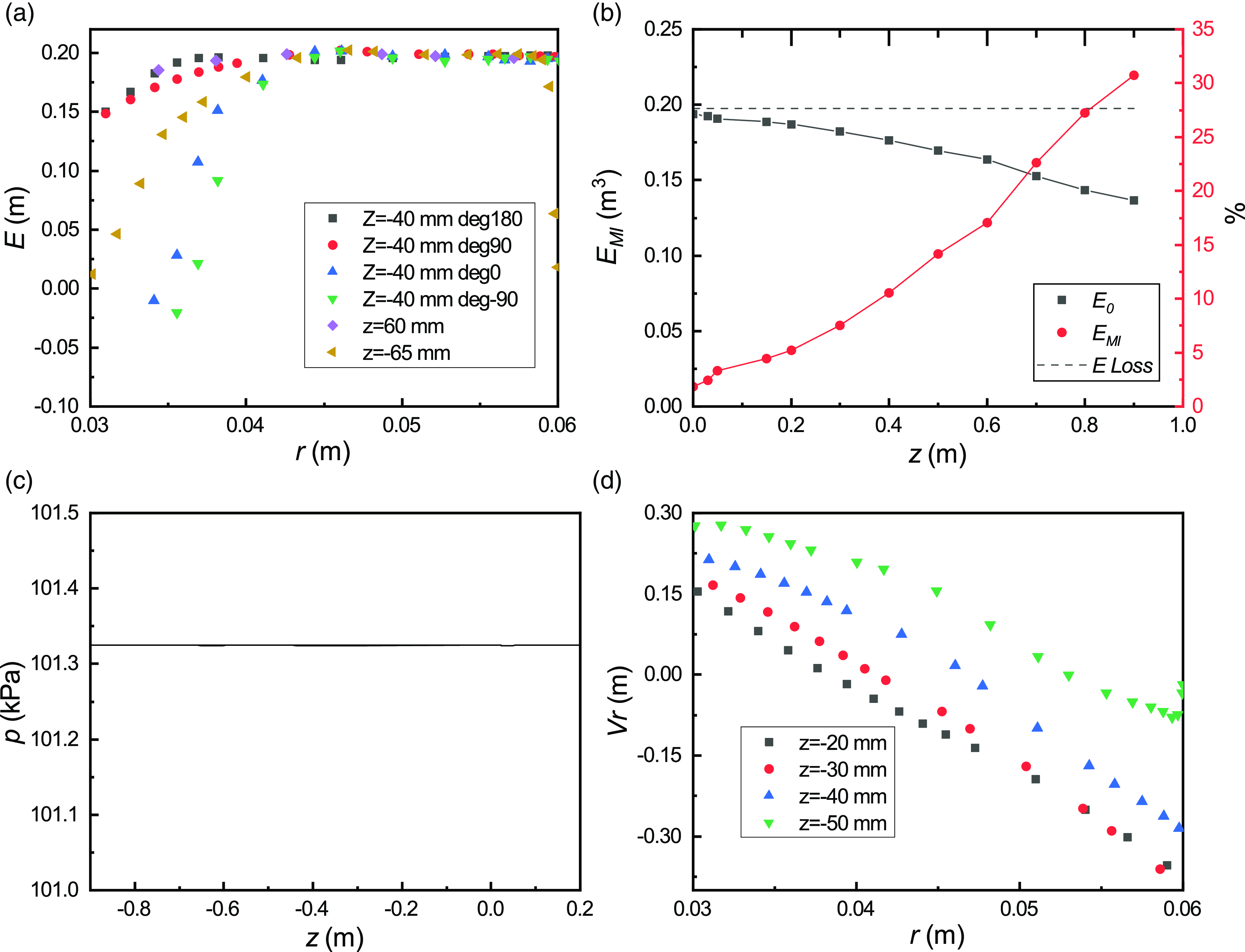
Figure 10. (a) Energy head E distribution, (b) mass integral of E over different cross-sections, (c) pressure along shaft central axis and (d) radial velocity distributions in the bell mouth.
These findings indicate that the assumptions used in traditional analytical models should be revisited, particularly in the context of transient flow conditions. The deviations observed in velocity distributions, energy dissipation, and radial velocity highlight the need for more comprehensive modelling approaches – such as LES – that can capture the complex, 3-D nature of flow within scroll vortex drop shafts. Incorporating transient flow analyses and detailed 3-D modelling into design practices will improve the reliability of hydraulic structures, enhancing their performance and resilience in real-world applications. Future studies should focus on validating these findings under different operational conditions and configurations to establish more accurate design guidelines.
4. Conclusions
This study presents a detailed investigation of transient flow characteristics in a drop shaft with a scroll vortex intake using LES. The time-averaged head-discharge relationship and minimum air-core percentage obtained from LES were compared with experimental data, and good agreement was found, affirming the validity of the simulation results. Focusing on the transient fluctuations of the air core, our analysis revealed significant variations in the air-core area – up to 13 % – which could have implications for the design of vortex intakes, particularly regarding hydraulic choking risks. Furthermore, the detailed examination of vortex structures using the $\Omega$
-criterion highlights the capability of LES to capture both large-scale and small-scale vortices, providing new perspectives on the vortex dynamics that traditional models might overlook.
$\Omega$
-criterion highlights the capability of LES to capture both large-scale and small-scale vortices, providing new perspectives on the vortex dynamics that traditional models might overlook.
Additionally, the study demonstrates that some long-standing assumptions in existing analytical models for vortex drop shafts may require re-examination, especially regarding the symmetry and energy dissipation within the drop shaft. The overall results also demonstrate the importance of incorporating transient flow analysis in design practices to ensure the reliability and safety of urban drainage systems under dynamic flow conditions.
In summary, this work contributes valuable insights into the transient phenomena occurring within vortex drop shafts, offering a pathway toward more accurate and resilient designs for urban drainage infrastructure. Future research should further explore transient effects under a broader range of flow conditions and consider their potential impact on large-scale urban drainage systems.
Supplementary material
The supplementary material for this article can be found at https://doi.org/10.1017/flo.2025.10015.
Data availability statement
All relevant data are included in the paper or its Supplementary Information.
Funding statement
This research received no specific grant from any funding agency, commercial or not-for-profit sectors.
Competing interests
The author(s) declare no conflict of interest.


 Open access