


1. Introduction
The study of the ophiolite-bearing suture zones preserved within orogenic collisional belts can provide important information on the pre-collisional geodynamic setting. They, in fact, bear fore- and back-arc ophiolite sequences (non-metamorphosed or affected by low- to high-pressure metamorphism) and/or magmatic rocks originated in a volcanic arc whose study may improve considerably the pre-collisional palaeogeographic reconstructions.
The Intra-Pontide suture (IPS) zone represents one of the first-order tectonic structures in northern Turkey (Sengör & Yılmaz, Reference Şengör and Yılmaz1981). It is located between the Istanbul–Zonguldak Terrane (IZ) to the north and the Sakarya Terrane (SK) to the south (e.g. Göncüoğlu, Dirik & Kozlu, Reference Göncüoğlu, Dirik and Kozlu1997; Göncüoğlu et al. Reference Göncüoğlu, Turhan, Senturk, Ozcan, Uysal, Bozkurt, Winchester and Piper2000) (Fig. 1) and consists of an E–W-trending assemblage of deformed and variably metamorphosed units, including sedimentary and magmatic rocks derived from a Neo-Tethyan oceanic basin (e.g. Göncüoğlu et al. Reference Göncüoğlu, Gürsu, Tekin and Koksal2008). Despite the IPS zone playing a key role in Mesozoic geodynamic reconstructions for the Eastern Mediterranean region, the tectonometamorphic history of its units of oceanic affinity has been poorly investigated.

Figure 1. (a) Tectonic map of the Anatolia peninsula. IZ – Istanbul–Zonguldak Terrane; SK – Sakarya Terrane; AT – Anatolide–Tauride Terrane; IPS – Intra-Pontide suture. Black line – ophiolite suture zones. (b) Schematic geological map of the Central Pontides.
We here present the results of a multidisciplinary research carried out on the Daday Unit from the Central Pontides (northern Turkey) introducing new constraints on the tectonic evolution of the IPS zone. This research combines lithological, structural and metamorphic investigations, and geochemical and radiometric (apatite fission-track and 40Ar–39Ar dating) studies. The resulting dataset is discussed in order to provide new insights for the reconstruction of the tectonic history of the IPS zone in the context of the Mesozoic–Tertiary geodynamic evolution of the Eastern Mediterranean region.
2. The Intra-Pontide suture zone: an overview
The geological setting of Turkey (Fig. 1a) is characterized by an assemblage of continental terranes separated by several ophiolite-bearing suture zones whose ages range from late Neoproterozoic to Cretaceous (Göncüoğlu, Dirik & Kozlu, Reference Göncüoğlu, Dirik and Kozlu1997 and references therein). This tectonic setting derives from the progressive accretion to the Eurasian plate of Gondwana-derived fragments as a consequence of the closure of several Palaeo- and Neo-Tethyan oceanic basins (e.g. Göncüoğlu, Dirik & Kozlu, Reference Göncüoğlu, Dirik and Kozlu1997). The result is an assemblage of continental terranes bounded by suture zones of different ages that mark the areas where the Palaeo-Tethyan and Neo-Tethyan oceanic basins were opened and subsequently destroyed by subduction and/or obduction processes (e.g. Okay & Whitney, Reference Okay and Whitney2010). The IPS zone is one of these ophiolitic-bearing suture zones. It is an assemblage of oceanic and continental units, extending more than 400 km through northern Turkey from the Aegean Sea to the Black Sea (Sengör & Yılmaz, Reference Şengör and Yılmaz1981; Göncüoğlu, Dirik & Kozlu, Reference Göncüoğlu, Dirik and Kozlu1997; Robertson & Ustaömer, Reference Robertson and Ustaömer2004) (Fig. 1a).
The published data (Sengör & Yılmaz, Reference Şengör and Yılmaz1981; Göncüoğlu et al. Reference Göncüoğlu, Erendil, Tekeli, Aksay, Kus and Ürgün1987, Reference Göncüoğlu, Gürsu, Tekin and Koksal2008, Reference Göncüoğlu, Marroni, Sayit, Tekin, Ottria, Pandolfi and Ellero2012, Reference Göncüoğlu, Marroni, Pandolfi, Ellero, Ottria, Catanzariti, Tekin and Sayit2014; Yılmaz, Reference Yılmaz1990; Göncüoğlu & Erendil, Reference Göncüoğlu and Erendil1990; Robertson et al. Reference Robertson, Clift, Degnan and Jones1991; Okay et al. Reference Okay, Satır, Maluski, Siyako, Monié, Metzger, Akyüz, Yin and Harrison M1996; Yılmaz et al. Reference Yılmaz, Tüysüz, Yiğitbaş, Genç, Şengör and Robinson1997; Okay & Tüysüz, Reference Okay, Tüysüz, Durand, Olivet, Horvath and Serrane1999; Okay, Reference Okay, Bozkurt, Winchester and Piper2000; Robertson & Ustaömer, Reference Robertson and Ustaömer2004; Akbayram, Okay & Satır, Reference Akbayram, Okay and Satır2013; Marroni et al. Reference Marroni, Frassi, Göncüoğlu, Di Vincenzo, Pandolfi, Rebay, Ellero and Ottria2014) indicate that the IPS zone was formed by the closure of an oceanic basin, known as the Intra-Pontide Ocean (IPO) basin, located between two continental margins today represented by the IZ Terrane, to the north, and the SK Terrane, to the south (Fig. 1a). The IPO basin was opened in Middle Triassic time (Tekin et al. Reference Tekin, Göncüoğlu, Pandolfi and Marroni2012) and was characterized from Middle Jurassic time by supra-subduction oceanic lithosphere (Göncüoğlu et al. Reference Göncüoğlu, Marroni, Sayit, Tekin, Ottria, Pandolfi and Ellero2012). The final closure of the Intra-Pontide oceanic basin leading to the collision between the Istanbul–Zonguldak and Sakarya terranes was recently constrained to before late Paleocene time in the Central Pontides (Catanzariti et al. Reference Catanzariti, Ellero, Göncüoğlu, Marroni, Ottria and Pandolfi2013), whereas it was before Santonian time in the Marmara region (Özcan et al. Reference Özcan, Okay, Özcan, Hakyemez and Özkan-Altıner2012; Akbayram, Okay & Satır, Reference Akbayram, Okay and Satır2013). Since late Miocene time, the IPS zone has been overprinted by the North Anatolian Fault (NAF) zone, a still active transform fault characterized by a wide damage zone that almost completely obliterates the pristine architecture of the IPS zone (e.g. Ellero et al. Reference Ellero, Ottria, Marroni, Pandolfi and Göncüoğlu2015a ). Where the original structure of the IPS zone is preserved the tectonic units are bounded by E–W-trending, low-angle shear zones (e.g. Frassi et al. Reference Frassi, Göncüoğlu, Marroni, Pandolfi, Ruffini, Ellero, Ottria and Sayit2016).
The assemblage of tectonic units belonging to the IPS zone is thrust by the IZ Terrane, which includes a Neoproterozoic basement (e.g. Ustaömer & Rogers, Reference Ustaömer and Rogers1999) unconformably overlain by a continuous, very thick sedimentary sequence spanning from the Ordovician to Carboniferous (e.g. Görür et al. Reference Görür, Monod, Okay, Şengör, Tüysüz, Yiğitbaş, Sakinc and Akkök1997). The non-metamorphic Palaeozoic sequence of the IZ Terrane (i.e. the Zonguldak Unit) is in turn unconformably overlain by a thick sequence of upper Permian – Triassic continental clastic deposits topped by Middle to Upper Jurassic carbonate deposits. They are in turn covered by Upper Cretaceous – Paleocene turbidite deposits (Akveren Flysch) interleaved with andesitic volcanic flows (e.g. Dizer & Meriç, Reference Dizer and Meriç1983; Aydın et al. Reference Aydin, Sahintürk, Serdar, Özçelik, Akarsu, Üngör, Ҫokuğraş and Kasar1986).
In turn, the units from the IPS zone and the IZ Terrane are thrust onto the SK Terrane consisting of a Variscan continental basement associated with a strongly deformed and metamorphosed Triassic subduction complex (i.e. the Karakaya Complex), which is unconformably covered by a non-metamorphic Lower Jurassic – middle Paleocene sedimentary cover. The lower portion of the Karakaya Complex was deformed and metamorphosed (from blueschist to eclogite-facies conditions) during Late Triassic time (Okay & Monié, Reference Okay and Monié1997; Okay, Monod & Monié, Reference Okay, Monod and Monié2002). The deformation and metamorphism documented in the Karakaya Complex testify to the subduction of the Palaeo-Tethys oceanic lithosphere mainly below the Laurasian continental margin during the ‘Cimmerian orogeny’ (e.g. Robertson & Ustaömer, Reference Robertson and Ustaömer2011). The resulting tectonic structures are unconformably sealed by Lower Jurassic continental to shallow-marine clastic rocks. They are in turn unconformably topped by Middle Jurassic to Lower Cretaceous neritic carbonates and Albian–Cenomanian pelagic limestones passing upwards to turbidite deposits (here reported as Taraklı Flysch) ranging in age from early Maastrichtian to middle Paleocene. The uppermost levels of the Taraklı Flysch show carbonate and ophiolite slide-blocks derived from both the IZ Terrane and IPS zone (Catanzariti et al. Reference Catanzariti, Ellero, Göncüoğlu, Marroni, Ottria and Pandolfi2013). The geological time scale follows the International Chronostratigraphic Chart v2016/04 (Cohen et al. Reference Cohen, Finney, Gibbard and Fan2013, updated)
3. A snapshot of the Intra-Pontide suture zone in the Central Pontides
In the Central Pontides, the IPS zone is an assemblage of several tectonic units characterized by different age, metamorphic imprint and deformation histories (Fig. 1b). The present-day tectonic setting can be described as a pre-late Paleocene imbricate stack where an ophiolite unit (Ayli Dağ ophiolite Unit) and an ophiolite-bearing mèlange (known by different names: Kirazbasi by Tüysüz, Reference Tüysüz1990; Araç Formation by Özcan, Less & Kertesz, Reference Özcan, Less and Kertesz2007; and Arkot Dağ Mèlange by Tokay, Reference Tokay1973 and Göncüoğlu et al. Reference Göncüoğlu, Marroni, Pandolfi, Ellero, Ottria, Catanzariti, Tekin and Sayit2014) are associated with four metamorphic units (Fig. 1b). In the pristine tectonic setting, the ophiolite unit and the ophiolite-bearing mèlange were probably at the top of the imbricate stack, above the metamorphic units.
The Ayli Dağ ophiolite Unit is characterized by a Middle Jurassic back-arc ophiolite sequence (Göncüoğlu et al. Reference Göncüoğlu, Marroni, Sayit, Tekin, Ottria, Pandolfi and Ellero2012) whereas the ophiolite-bearing mèlange is a sedimentary mèlange characterized by slide-blocks of continental and oceanic origin set in an Upper Cretaceous sedimentary matrix. The four metamorphic units (i.e. Central Pontide Structural Complex (CPSC) of Tekin et al. Reference Tekin, Göncüoğlu, Pandolfi and Marroni2012 or Central Pontides Supercomplex (CPS) of Okay et al. Reference Okay, Sunal, Sherlock, Altiner, Tüysüz, Kylander-Clark and Aygül2013; hereafter both referred to as the CPSC, Fig. 1b) are characterized by fragments of oceanic lithosphere deformed and metamorphosed in a subduction setting (e.g. Okay, Satır & Siebel, Reference Okay, Satır, Siebel, Gee and Stephenson2006; Okay et al. Reference Okay, Sunal, Sherlock, Altiner, Tüysüz, Kylander-Clark and Aygül2013; Marroni et al. Reference Marroni, Frassi, Göncüoğlu, Di Vincenzo, Pandolfi, Rebay, Ellero and Ottria2014; Aygül et al. Reference Aygül, Okay, Oberhansli, Schmidt and Sudo2015 b) (see Table 1 for the literature correlations).
The metamorphic unit affected by the highest metamorphic grade (i.e. Domuz Dağ Unit; Okay, Satır & Siebel, Reference Okay, Satır, Siebel, Gee and Stephenson2006) is an assemblage of slices of metasedimentary rocks, metabasites and metaserpentinites cropping out in the Kargi Massif (Fig. 1b). The metabasites include eclogites, garnet- and glaucophane-bearing amphibolites, and albite- and chlorite-bearing schists. On the basis of 40Ar–39Ar dating the eclogite-facies metamorphism took place in Early Cretaceous time (~ 105 Ma, Okay, Satır & Siebel, Reference Okay, Satır, Siebel, Gee and Stephenson2006). A second high-grade metamorphic unit is represented by the Saka Unit (cf. the Devrekani Unit of Marroni et al. Reference Marroni, Frassi, Göncüoğlu, Di Vincenzo, Pandolfi, Rebay, Ellero and Ottria2014 and Saka Complex of Okay et al. Reference Okay, Sunal, Sherlock, Altiner, Tüysüz, Kylander-Clark and Aygül2013). This unit, less than 300 m in thickness, was recognized exclusively in the Daday Massif (Figs 1b, 2). It consists of slices of garnet-bearing amphibolites (affected by a retrograde metamorphism ranging from greenschist to sub-greenschist-facies conditions; Marroni et al. Reference Marroni, Frassi, Göncüoğlu, Di Vincenzo, Pandolfi, Rebay, Ellero and Ottria2013), coarse-grained banded amphibolites, garnet-bearing micaschists and coarse-grained impure marbles. In the garnet-bearing amphibolites, P = 0.8–0.99 GPa and T = 600 °C calculated at metamorphic peak occurred during Late Jurassic time (~ 163 Ma: 40Ar–39Ar dating; Marroni et al. Reference Marroni, Frassi, Göncüoğlu, Di Vincenzo, Pandolfi, Rebay, Ellero and Ottria2014). The third metamorphic unit is represented by the Daday Unit (cf. Martin Complex of Okay et al. Reference Okay, Sunal, Sherlock, Altiner, Tüysüz, Kylander-Clark and Aygül2013) that is described in detail in the sections below. The Emirköy Unit represents the fourth metamorphic unit of the CPSC. It is made up of a monotonous succession of metaturbidites affected by very low-grade metamorphic conditions. No ophiolite bodies and/or clasts have been found in this unit. The upper Paleocene – middle Eocene shallow-water deposits of the Karabük–Kastamonu Basin (Özcan, Less & Kertesz, Reference Özcan, Less and Kertesz2007) unconformably sealed the relationships among the metamorphic units of the CPSC, the Ayli Dağ ophiolite Unit and the Arkot Dağ Melange.

Figure 2. Geological sketch map of the Intra-Pontide suture zone in the Daday Massif (see Fig. 1b for map location). Stereographic projections of the main structural elements (S2 – S2 foliation; A2 – axes of F2 folds; S3 – S3 foliation; A3 – axes of F3 folds; S4 – S4 foliation; A4 – axes of F4 folds) are also shown (equal area, lower hemisphere). CPSC – Central Pontide Structural Complex (Tekin et al. Reference Tekin, Göncüoğlu, Pandolfi and Marroni2012).
It is important to outline the sharp metamorphic gap existing among the non-metamorphosed Ayli Dağ ophiolite Unit and the Arkot Dağ Melange, and the four metamorphic units. This gap clearly indicates the association in the same tectonic stack of tectonic units deformed and metamorphosed at different structural levels.
In addition, a weakly metamorphosed volcanic-rock-bearing succession was documented within elongated blocks bounded by strike-slip faults along the NAF zone south of Tosya (the Tafano Unit: Ellero et al. Reference Ellero, Ottria, Sayit, Catanzariti, Frassi, Göncüoğlu, Marroni and Pandolfi2015b ; Fig. 1b). This unit consists of basalts to basaltic andesites topped by uppermost Santonian – middle Campanian turbidites. The geochemistry of the volcanic rocks (Ellero et al. Reference Ellero, Ottria, Sayit, Catanzariti, Frassi, Göncüoğlu, Marroni and Pandolfi2015b ; Sayit et al. Reference Sayit, Marroni, Göncüoğlu, Pandolfi, Ellero, Ottria and Frassi2016) indicates that this succession represents the remains of a continental arc, whose palaeogeographical location inside the IPO domain is still undetermined. Moreover, into another block along the NAF zone, Berber, Göncüoğlu & Sayit (Reference Berber, Göncüoğlu and Sayit2014) and Aygül et al. (Reference Aygül, Okay, Oberhansli, Schmidt and Sudo2015 a) documented a succession consisting of Cenomanian–Turonian andesites and sedimentary rocks, metamorphosed during Maastrichtian time under low greenschist-facies conditions. On the whole, the picture arising from the IPS zone seems to indicate the occurrence of elements of a convergent margin whose geodynamic history is still matter of debate.
4. The Daday Unit
In the Daday Massif (north-central Turkey; Fig. 1b), the easternmost segment of the IPS zone crops out in the mountains between Daday town, in the north, and Hatipköy and Cavusköy, in the south (Fig. 2). In this area, the metamorphic units of the IPS zone are imbricated with slices of the Ayli Dağ ophiolite Unit and the Arkot Dağ Mélange (Tokay, Reference Tokay1973) onto the Taraklı Flysch (Late Cretaceous – middle Paleocene age: Catanzariti et al. Reference Catanzariti, Ellero, Göncüoğlu, Marroni, Ottria and Pandolfi2013) that represents the sedimentary cover of the SK Terrane (Fig. 2). In turn, the units from the IPS zone are topped by klippens of the IZ Terrane as documented c. 20 km east of Araç. The uppermost Paleocene – middle Eocene deposits of the Karabük–Kastamonu basin seal the relationships among the IZ and SK terranes and the IPS zone. Two different metamorphic units crop out in the study area: the Saka Unit and the Daday Unit. The latter is the object of this study and is described in detail in the two sections below: in the first section, we present the results of our lithological, geochemical and structural investigations, whereas in the second, we reconstruct its pressure–temperature–time (P–T–t) path using new pressure–temperature estimates and new 40Ar–39Ar and apatite fission-track (AFT) ages.
4.a. Lithological and structural overview
The study of the Daday Unit started with classic field investigations during which we conducted a detailed description of lithotypes and mesostructures as well as the measurements of the different structural elements (e.g. foliations, folds, mineral lineations and faults) (Figs 2, 3). A total of 45 samples, representative of each lithotype and fabric, were collected in the Daday Unit. They were cut parallel to the mineral lineation and orthogonal to the main foliation and investigated using polarized light microscopy.

Figure 3. Geological cross-section of the Intra-Pontide suture zone along the Araç–Daday transect (see Fig. 2 for location).
Five samples of mafic rocks were selected to conduct geochemical analyses (see Fig. 2 for sample location and online Supplementary Material S2 for GPS coordinates available at https://doi.org/10.1017/S0016756817000176) (Sayit et al. Reference Sayit, Marroni, Göncüoğlu, Pandolfi, Ellero, Ottria and Frassi2016). Analyses of major elements were determined by inductively coupled plasma emission spectrometry (ICP-ES) and trace elements (including rare earth elements (REEs)) were determined by inductively coupled plasma mass spectrometry (ICP-MS) at the ACME analytical labs (Canada) (see online Supplementary Material S3 for geochemical analyses available at https://doi.org/10.1017/S0016756817000176).
4.a.1. Lithological overview
In the field, the Daday Unit is characterized by a block-in-matrix fabric derived from a strong partitioning of the ductile deformation (D2 phase, see section 4.a.3 below). The result is in an assemblage of metre- to kilometre-thick tectonic slices with a lozenge shape, bounded by ductile to brittle–ductile shear zones. The tectonic slices have a monogenic composition that consists of different lithotypes including fine-grained micaschists (~35 vol. %) (Fig. 4a), fine- to coarse-grained paragneisses (~25 vol. %), (impure) marbles (~20 vol. %) (Fig. 4b), dark to white quartzites (~5 vol. %) (Fig. 4c) and actinolite-bearing schists (~15 vol. %) (Fig. 4d). The protoliths of the fine-grained micaschists and the fine- to coarse-grained paragneisses are shales, siltites and arenites, whereas those of the actinolite-bearing schists are mafic rocks. The protoliths of the fine-grained dark and thin-bedded quartzites are probably represented by cherts whereas those of the white, thick-bedded quartzites display typical stratigraphic, micro-textural and mineralogical features of quartz-arenites. No fossils were found in the rocks of the Daday Unit. However, U–Pb dating of detrital zircons obtained by Okay et al. (Reference Okay, Sunal, Sherlock, Altiner, Tüysüz, Kylander-Clark and Aygül2013) from a sample of paragneiss suggests a minimum depositional age of 171 Ma.

Figure 4. Metamorphic rocks of the Daday Unit cropping out in the Araç area. (a) Micaschists. (b) Marble. (c) Quartzites. (d) Actinolite-bearing schist. S0 – bedding; S2 – S2 foliation. Hammer for scale is 27 cm long; diameter of coin is 1.6 cm.
The mylonitic foliation within the shear zones bounding the tectonic slices is the main foliation documented in the field (i.e. S2 foliation, see section 4.a.3 below). As a consequence, the original relationships among the different lithotypes cannot be detected. Non-deformed and non-metamorphosed basic dykes intrude the metamorphic rock assemblage.
The field distribution of the different lithotypes is not homogeneous across the whole study area and often the thickness of the tectonic slices is too small to be represented on the map. As a consequence, only the biggest bodies of marbles and actinolite-bearing micaschists we represented in Figure 2.
4.a.2. Geochemistry of the metamorphic mafic rocks
The immobile element systematics indicate that the protoliths of the metamorphic mafic rocks sampled in the study area (see Fig. 2 for sample location) are of basaltic composition and display subalkaline characteristics (Nb/Y = 0.07–0.27) (Fig. 5). The trace-element characteristics further reveal that the protoliths can be subdivided into two distinct chemical types. The first type (Type 1) is characterized by the highly depleted HFSE (high-field-strength element) concentrations, reflecting boninitic, island arc basalt (IAB)-like characteristics (ZrM = 0.07–0.22, HfM = 0.1–0.2, YM = 0.06–0.27, where ‘M’ denotes normal mid-ocean ridge (N-MORB)-normalized) (Fig. 6). The second type (Type 2) displays back-arc basin basalt (BABB)-like features, as reflected by N-MORB-like HFSEs and a HREE (heavy rare earth element) distribution associated with a negative Nb anomaly (Nb/Nb* = 0.5–0.6) (Fig. 6).
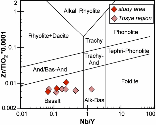
Figure 5. Chemical classification of the metamorphic mafic rocks from the Daday Unit exposed in the study area and the Tosya region (after Winchester & Floyd, Reference Winchester and Floyd1977, modified by Pearce, Reference Pearce and Wyman1996) (Alk-Bas – alkali basalt; And – andesite; Bas-And – basaltic andesite; Trachy-And – trachyandesite). Note that two samples from the study area do not appear in the plot either due to very low Nb content or that Nb remained below the detection limit.

Figure 6. Trace-element (left column) and REE (right column) patterns of the metabasic rocks form the Daday Unit exposed in the study area and in the Tosya region. Normalization values from Sun & McDonough (Reference Sun, McDonough, Saunders and Norry1989).
The presence of these distinct chemical types within the Daday Unit may be attributed to derivation from distinct mantle source regions and/or various degrees of partial melting. Type 1, with highly depleted HFSE features, requires a mantle source that has experienced a previous melt extraction. Type 2, with relatively more enriched signatures compared to the former group, reflects a mantle source region relatively similar to that of N-MORBs (i.e. depleted asthenospheric mantle source). The extreme depletions reflected by Type 1 Daday metamorphic mafic rocks are typical in boninitic magmas generated largely in the fore-arc regions of oceanic arcs (e.g. Crawford, Beccaluva & Serri, Reference Crawford, Beccaluva and Serri1981; Cameron, Culloch & Walker, Reference Cameron, Culloch and Walker1983; Bedard, Reference Bedard1999). The trace-element signatures of Type 2 samples, on the other hand, appear to be similar to the magmas formed in back-arc regions of intra-oceanic subduction systems (e.g. Pearce et al. Reference Pearce, Stern, Bloomer and Fryer2005).
4.a.3. Deformation history
The oldest deformation phase recognized in the field, the D1 phase, is testified to by S1 continuous foliation folded by rare centimetre-sized F2 isoclinal folds. At the microscopic scale, S1 foliation was documented within D2 microlithons in the fine-grained micaschists, paragneisses and marble. In the fine-grained micaschists, it is highlighted by 1 to 3 mm thick granoblastic layers made of elongate quartz and feldspar grains and oxides and less than 1 mm thick lepidoblastic layers of white micas (phengite) and chlorite crystals (70–120 µm) (Fig. 7a–c), whereas in the actinolite-bearing schists and impure marbles it is marked by 60–130 µm white micas and chlorite flakes oriented and/or folded at a high angle with respect to the external S2 foliation (Fig. 7b).

Figure 7. Meso- and microstructures documented in the Daday Unit. (a) Thin-section photomicrograph of micaschist (cross-polarized light, XPL). Phengite crystals (Phg) grew along the S1 foliation (S1). (b) Backscattered scanning electron microscope (SEM) image showing chlorite (Chl) and phengite (Phg) crystals grew along the S1 foliation (S1). (c) S1 foliation (S1) deformed by isoclinal F2 fold. (d) Thin-section photomicrograph of actinolite (Act)-bearing schist (XPL). (e) Backscattered SEM image of actinolite (Act)-bearing schist. (f) Micaschists deformed by F3 folds. (g) Thin-section photomicrograph of fine-grained micaschists (plain-polarized light, PPL). (h) Relationship between the four deformation phases documented in the field. Abbreviations: S1 – S1 foliation; S2 – S2 foliation; S3 – S3 foliation; S4 – S4 foliation; AP3 – F3 axial plane; AP4 – F4 axial plane; Ab – albite; Chl – chlorite; Ep – epidote; Px – pyroxene. Diameter of the coin for scale is 1.6 cm.
The second deformation phase (D2) produced the main structures documented in the field and results in strongly partitioned folded and sheared domains. The latter are localized at the boundaries of the lozenge-shaped tectonic slices, so at the boundaries between the different lithotypes, whereas the former are preserved within each slice. The mylonitic domains are marked by centimetre-scale S–C structures pointing to a top-to-the-S sense of shear. Tight to isoclinal F2 folds, well developed within the fine-grained micaschists and paragneisses, have a symmetric profile with a thickened hinge, thinned and delaminated limbs and a sub-rounded up to sub-angular hinge profile (Fig. 7c). A2 fold axes mostly trend from NW–SE to NNE–SSW with a main trend of 115–140° plunging 20–40° towards the SW (Fig. 2). The main D2 structure documented in the field is the S2 foliation (Fig. 4). It develops heterogeneously as axial plane and mylonitic foliation and shows variable orientation from W–E to SW–NE and dips mainly towards the west (Fig. 2). Along the limbs of the F2 folds, the parallelism between the S1 and S2 foliation leads to a composite foliation, whereas in the hinge zone, the S2 axial plane foliation wraps relics of S1.
In the marble, S2 foliation is highlighted by spaced (from 0.2 to 0.5 cm) fractures and/or pressure solution surfaces. At the microscopic scale, in the fine-grained micaschists S2 foliation is a continuous foliation highlighted by compositional layers made of very fine-grained muscovite ± rutile (± chlorite) and quartz + albite ± calcite ± chlorite. In the paragneisses, it is marked by an irregular network of 100 µm thick layers of white mica and rutile wrapping quartz + feldspar aggregates and quartz (0.5–2 mm) grains. Quartz shows undulatory extinction, deformation bands, rare shape preferred orientation and evidence of both subgrain rotation and grain boundary migration intracrystalline recrystallization. In the impure marbles, S2 foliation is marked by less than 80 µm thick discontinuous layers of fine-grained white micas (phengite and chlorite), oriented calcite crystals (30–50 µm) and locally, irregular and discontinuous dark seams of oxides and insoluble materials along dissolution surfaces. In the impure marbles, quartz shows evidence of weak intracrystalline deformation with undulatory extinction, deformation bands and evidence of subgrain rotation and dynamic recrystallization. In the actinolite-bearing micaschists, S2 foliation is a continuous foliation marked by chlorite + actinolite + epidote ± ilmenite and elongated quartz and albite grains (Fig. 7d, e). It wraps relics of brown amphibole, pyroxene, plagioclase (Fig. 7d), kinked muscovite and rare biotite (almost completely replaced by chlorite), ranging in size from 100 to 400 µm. Quartz shows both shape and crystal preferred orientation, a bimodal grain-size distribution, undulatory extinction, deformation bands and evidence of subgrain rotation recrystallization, indicating deformation temperatures of 400–500 °C (Stipp et al. Reference Stipp, Stünitz, Heilbronner and Schmid2002).
The D3 phase is mainly represented by cylindrical F3 folds that show interlimb angles ranging from 30° to 120° and sub-angular to sub-rounded hinge zones (Fig. 7f–h). Within the schist/paragneiss multilayers (i.e. metaturbidites), they can be classified as types 3 and 1B folds (Ramsay, Reference Ramsay1967). The L(S0–S3) intersection lineation is mainly represented by S3 foliation–S0 bedding intersection and mullion structures. A3 fold axes trend mainly from NW–SE to NNW–SSE, steeply plunging (50–80°) mainly towards the SW (Fig. 2). S3 foliation is a spaced axial plane crenulation cleavage (Fig. 7g) mainly oriented NNE–SSW to NE–SW with a gentle dip (< 20°) mainly towards the SE (Fig. 2). At the microscopic scale, it is marked by rough to smooth cleavage domains highlighted by thin films of opaque minerals and oxides along dissolution surfaces (Fig. 7g). No evidence of mineralogical lineation has been detected on the S3 foliation. F3 folds are associated with ~ WNW–ESE-trending thrusts dipping from 20° to 60° towards the north associated with centimetre-thick brittle shear zones pointing to a top-to-the-S sense of shear.
The D4 phase produced parallel folds (type 3, Ramsay, Reference Ramsay1967) with interlimb angles ranging from 160° to 80° and rounded hinges (Fig. 7h). They show sub-horizontal axial planes and A4 axes variably trending from W–E to NW–SE, shallowly plunging mainly towards the west. The axial plane foliation is represented by a disjunctive cleavage without syn-kinematic re-crystallization (Fig. 7g). Associated with the F4 folds, extensional brittle shear zones reactivated the pre-existing D3 thrusts indicating a top-to-the-N sense of shear.
The last deformation phase, D5, was documented only at the map scale. It produced kilometre-scale open folds with sub-vertical axial planes and ~ NNE–SSW-trending axes (Figs 2, 3). They are associated with high-angle strike-slip or oblique faults belonging to the Araç Fault zone (Ellero et al. Reference Ellero, Ottria, Marroni, Pandolfi and Göncüoğlu2015 a) that dissect both the tectonic nappe stack and the Eocene deposits (Figs 2, 3). The main fault system is represented by dextral faults oriented ~ WSW–ENE that are dissected by antithetical faults oriented ~ NNE–SSW. A minor fault system is directed ~WNW–ESE. Locally, N-dipping, low-angle thrust faults were documented in the Eocene deposits in the north of Siragömü Village.
Table 1. Correlation table showing the relationships between the Daday Unit and the different tectonometamorphic units within the IPS zone. The correlation is based on both metamorphic/lithological features and location on the geological maps

4.b. Constraining the P–T–t path of the Daday Unit
Thin-sections obtained from the collected samples were used to investigate the relationship between deformation and metamorphism. In order to characterize the mineral chemistry of the equilibrium phase assemblages, three samples were selected and investigated using a JEOL JXA-8200 Super Probe electron microprobe (EMP), equipped with four wavelength-dispersive spectrometers located at the Dipartimento di Scienze della Terra – Università di Milano, Milano (Italy). Chemical compositions of chlorites and white micas were used to obtained chlorite–phengite multi-equilibrium thermodynamic calculations on one selected sample (see Table 2 for representative analyses).
Table 2. Electron microprobe analyses of representative phengite (Phe) and chlorite (Chl) used for thermodynamic calculations in sample TC84 (impure marble)

In order to constrain the age of metamorphism, 40Ar–39Ar analyses were conducted on two white mica separates (see Fig. 2 for samples location) at Group 18 Laboratories of the Arizona State University (USA). Finally, one sample from the Daday Unit and one sample from the Saka Unit were selected to constrain the final stage of exhumation using AFT analyses performed at the CNR-IGG Pisa laboratory (Italy). For further information about the methodology used and for the complete dataset (mineral chemistry, pressure–temperature estimates, 40Ar–39Ar data and AFT results) see the online Supplementary Material available at https://doi.org/10.1017/S0016756817000176.
4.b.1. Mineral chemistry
The three samples selected for mineral chemistry analysis are: a fine-grained micaschist (sample TC57), an impure marble (sample TC84) and an actinolite-bearing schist (sample TC83) (see Fig. 2 for sample locations and online Supplementary Material S2 available at https://doi.org/10.1017/S0016756817000176 for GPS coordinates). In the metasediments, the metamorphic assemblage associated with the S1 foliation is made up of quartz + phengite + chlorite ± albite, meanwhile in the metabasites the metamorphic assemblage is hornblende + plagioclase + phengite + chlorite ± biotite. The S2-related assemblage is composed of quartz + phengite + chlorite ± albite ± calcite and actinolite + epidote + quartz + phengite + chlorite ± albite ± ilmenite in the metasedimentary (TC57–TC84) and mafic rocks (TC83), respectively.
Chlorite (Chl): chlorite structural formulae were calculated on the basis of 14 oxygens and Fe content is shown as divalent (Fetot) (online Supplementary Material Tables S1 and S4 available at https://doi.org/10.1017/S0016756817000176). Chlorites from sample TC84 have high clinochlore–daphnite end-member contents in respect to those in sample TC57 (see online Supplementary Material Table S4 available at https://doi.org/10.1017/S0016756817000176). In the same sample, they have Si contents between 2.58 and 2.77 apfu (atom per formula unit) and Mg/(Mg + Fe2+ + Mn) ratios ranging from 0.49 to 0.55 (Fig. 8a; online Supplementary Material Table S4 available athttps://doi.org/10.1017/S0016756817000176). Chlorites from sample TC57 have Si contents between 2.59 and 3.06 apfu and Mg/(Mg + Fe2+ + Mn) ratios ranging from 0.39 to 0.49 (online Supplementary Material Table S4 available at https://doi.org/10.1017/S0016756817000176). Chlorites that grew along the S1 foliation have high amesite end-member contents and higher Si contents (2.69–2.76 apfu) with respect to those that grew along the S2 foliation (Table 2; see online Supplementary Material Table S4 available at https://doi.org/10.1017/S0016756817000176).

Figure 8. Compositional variability of chlorite (a) and phengite (b) used for thermodynamic calculations (sample TC84, impure marble). (a) Mg/(Mg + Fe2+) versus Si (apfu) diagram. (b) Al (apfu) versus Si (apfu) diagram.
Phengite (Phe): Phengite structural formulae were calculated assuming 11 oxygens and all Fe as Fe2+ (online Supplementary Material Tables S1 and S4 available at https://doi.org/10.1017/S0016756817000176). If a small proportion of the Fe in the phengite was Fe3+, there would be a slight decrease in the Si content in the range typically < 0.1 apfu relative to the Fe3+-free case (e.g. Tribuzio & Giacomini, Reference Tribuzio and Giacomini2002). Phengites in sample TC84 have higher celadonite end-member contents relative to the muscovite end-member with respect to phengites in sample TC57 (Fig. 8b; Table 2). They show slightly higher Si contents (3.00–3.37 apfu) in sample TC84 compared to Si contents of between 3.00 and 3.19 apfu in sample TC57 (online Supplementary Material Table S4 available at https://doi.org/10.1017/S0016756817000176). Moreover, in each sample, the phengites are not arranged in clusters with different compositions but are distributed along a continuous range. Phengites that grew along the S1 foliation have slightly higher muscovite end-member contents and slightly higher Si contents (3.30–3.39 apfu) with respect to those that grew along the S2 foliation (Fig. 8b; Table 2).
Other minerals: from the actinolite-bearing schist (sample TC82), albite, amphibole and epidote were analysed. All analysed albite, the structural formulae of which were calculated assuming 8 oxygens, have compositions close to the pure end-member. For the analysed amphiboles structural formulae were calculated assuming 23 oxygens (see online Supplementary Material Table S1 available at https://doi.org/10.1017/S0016756817000176), and the classification of Leake et al. (Reference Leake, Wooley, Arps, Birch, Gilbert, Grice, Hawthorne, Kato, Kisch, Krivovichev, Linthout, Laird, Mandarino, Maresch, Nickel, Rock, Schumacher, Smith, Stephenson, Ungaretti, Whittaker and Youzhi1997) was adopted. Site assignment and ferric iron contents were calculated using the scheme proposed by Schumacher in Leake et al. (Reference Leake, Wooley, Arps, Birch, Gilbert, Grice, Hawthorne, Kato, Kisch, Krivovichev, Linthout, Laird, Mandarino, Maresch, Nickel, Rock, Schumacher, Smith, Stephenson, Ungaretti, Whittaker and Youzhi1997). The analysed amphiboles on the main foliation are actinolite with Mg/(Mg + Fe2+) ratios ranging from 0.51 to 0.74 and are characterized by Si contents ranging from 7.51 to 7.83 apfu. Analysed relics of brown amphibole show core to rim zonation, with Mg-hornblende/Mg-tschermakite cores and actinolite rims. The Mg-hornblende/Mg-tschermakite shows Mg/(Mg + Fe2+) ratios ranging from 0.72 to 0.95 and Si content ratios ranging from 6.33 to 6.57 apfu. Actinolite rims shows Mg/(Mg + Fe2+) ratios ranging from 0.63 to 0.65 and Si content ratios ranging from 7.59 to 7.60 apfu. For the analysed epidotes structural formulae were calculated assuming 12.5 oxygens and all Fe as Fe3+. The pistacite component in the epidote ranges from 0.12 to 0.14.
4.b.2. Metamorphic evolution
Sample TC84 (impure marble) was selected for the chlorite–phengite multi-equilibrium thermodynamic technique (Vidal & Parra, Reference Vidal and Parra2000; for analytical description see online Supplementary Material S1, whereas for pressure and temperature estimates see online Supplementary Material S6 available at https://doi.org/10.1017/S0016756817000176). In this sample several chlorite–phengite pairs, both on the S1 and on the S2 foliation, were preliminary selected using classic textural and microstructural criteria (e.g. minerals in contact, no evidence of reaction, grown in the same microstructure). In order to eliminate mineral compositions that do not form a linear combination of the end-members used in the chlorite – white mica solid-solution models a further selection was made on the basis of the chemical criteria.
Pressure–temperature conditions at the Chl–Phe–Qtz–H2O equilibrium were estimated using different chlorite–phengite pairs from sample TC84 (Fig. 9 and online Supplementary Material S5 available at https://doi.org/10.1017/S0016756817000176). If σP > 0.08 GPa and/or σT > 25 °C the assemblages are considered to be out of equilibrium and the P–T estimates are rejected. The P–T points constrained by the composition of selected chlorite–phengite pairs define a continuous trend on the diagram, characterized by temperatures ranging from ~ 220 to ~ 500 °C and pressures ranging from ~ 1.20 to ~ 0.55 GPa (Fig. 9). The Chl–Phe pairs that grew along the S1 foliation constrain a P–T path (Fig. 9) characterized by a very low-temperature metamorphic gradient (~ 6–12 °C km−1) whereas the Chl–Phe pairs that grew along the S2 foliation define a path characterized by an increase in temperature (up to ~ 500 °C), associated with a decrease in pressure (up to ~ 0.55 GPa). Therefore, the continuous trend shown by the points in the P–T diagram (Fig. 9) probably defines the exhumation path of the rocks belonging to the Daday Unit from the blueschist facies (D1 phase) to medium/high-pressure and medium-temperature conditions typical of the greenschist – lower-pressure epidote blueschist facies, D2 phase; Fig. 9). In the actinolite-bearing schists, the presence of Mg-hornblende/Mg-tschermakite, crystals partly replaced by actinolite rims, associated with chlorite, epidote, quartz and rare albite is consistent with the metamorphic facies obtained by thermodynamic calculations.
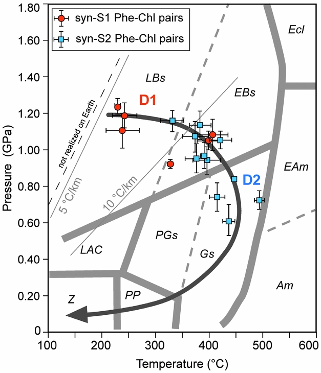
Figure 9. Estimated metamorphic P–T conditions in the Daday Unit metasedimentary rocks. Calculated Chl–Phe–Qtz–H2O equilibrium P–T conditions using different Phe–Chl pairs (local equilibria method of Vidal & Parra, Reference Vidal and Parra2000) from sample TC84. The average P–T estimates and the scatter of intersection (σT and σP) were calculated using INTERSX software (Berman, Reference Berman1991). Stability fields of the metamorphic facies are from Frost & Frost (Reference Frost and Frost2013). Abbreviations: Am – amphibolite facies; EAm – epidote amphibolite facies; Ecl – eclogite facies; EBs – epidote blueschist facies; LBs – lawsonite blueschist facies; PGs – pumpellyite greenschist facies; Gs – greenschist facies; LAC – lawsonite–albite–chlorite; PP – prehnite–pumpellyite facies; Z – zeolite facies.
4.b.3. 40Ar–39Ar metamorphic ages and AFT data
To constrain the age of metamorphism, we performed 40Ar–39Ar step-heating analysis of two metamorphic white mica separates obtained from samples 4-5-12 and 8-7-11 (see Fig. 2 for location and online Supplementary Material S1, S2 and S6 available at https://doi.org/10.1017/S0016756817000176). In both samples, the main foliation is an S2 continuous foliation marked by fine-grained white micas ± rutile (± chlorite) layers wrapping irregular sub-millimetre-thick layers of quartz, albite and relics of large (80–160 μm) white mica preserved within D2 microlithons and oriented at a high angle with respect to the external S2 foliation (i.e. marking the S1 foliation). Large white mica separates gave Late Jurassic ages ranging from c. 151 to c. 158 Ma (Fig. 10). The 40Ar–39Ar white mica plateau age is constrained at 156.66 ± 0.46 Ma and 157.7 ± 2.0 Ma for samples 8-7-11 and 4-5-12, respectively (base of the Kimmeridgian age, Fig. 10a, c). In sample 4-5-12, excluding the first three steps, the remaining give a well-defined linear array (MSWD = 0. 81) in the 36Ar–40Ar v. 40Ar–39Ar isochron plot, with an intercept age of 157.6 ± 3.4 Ma (Fig. 10b).
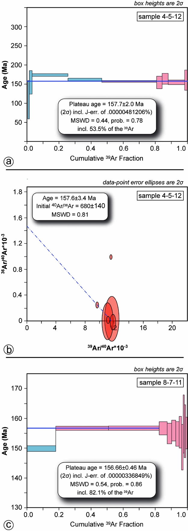
Figure 10. Results of 40Ar–39Ar laser step-heating experiments on white mica separates from sample 4-5-12 (a, b) and sample 8-7-11 (c). In (a) and (c) plateau steps are red, rejected steps are blue.
To constrain the exhumation at shallower structural levels, we performed AFT analysis on two samples, one from a garnet micaschist (FT4) and one from a metarenite (FT6) (see Fig. 2 for sample location and online Supplementary Material S1, S2 and S7 available at https://doi.org/10.1017/S0016756817000176). They yielded central ages of 57.7 ± 3.8 Ma and 58.0 ± 4.4 Ma, respectively (Fig. 11). We managed to measure a consistent number of confined track lengths (> 50) in both samples with a mean length of 14.15 ± 0.23 µm and 13.53 ± 1.43 µm, respectively. Dpar is 1.9 ± 0.42 µm and 2.0 ± 0.33 µm, respectively. There is no noticeable correlation between single grain ages and Dpar.
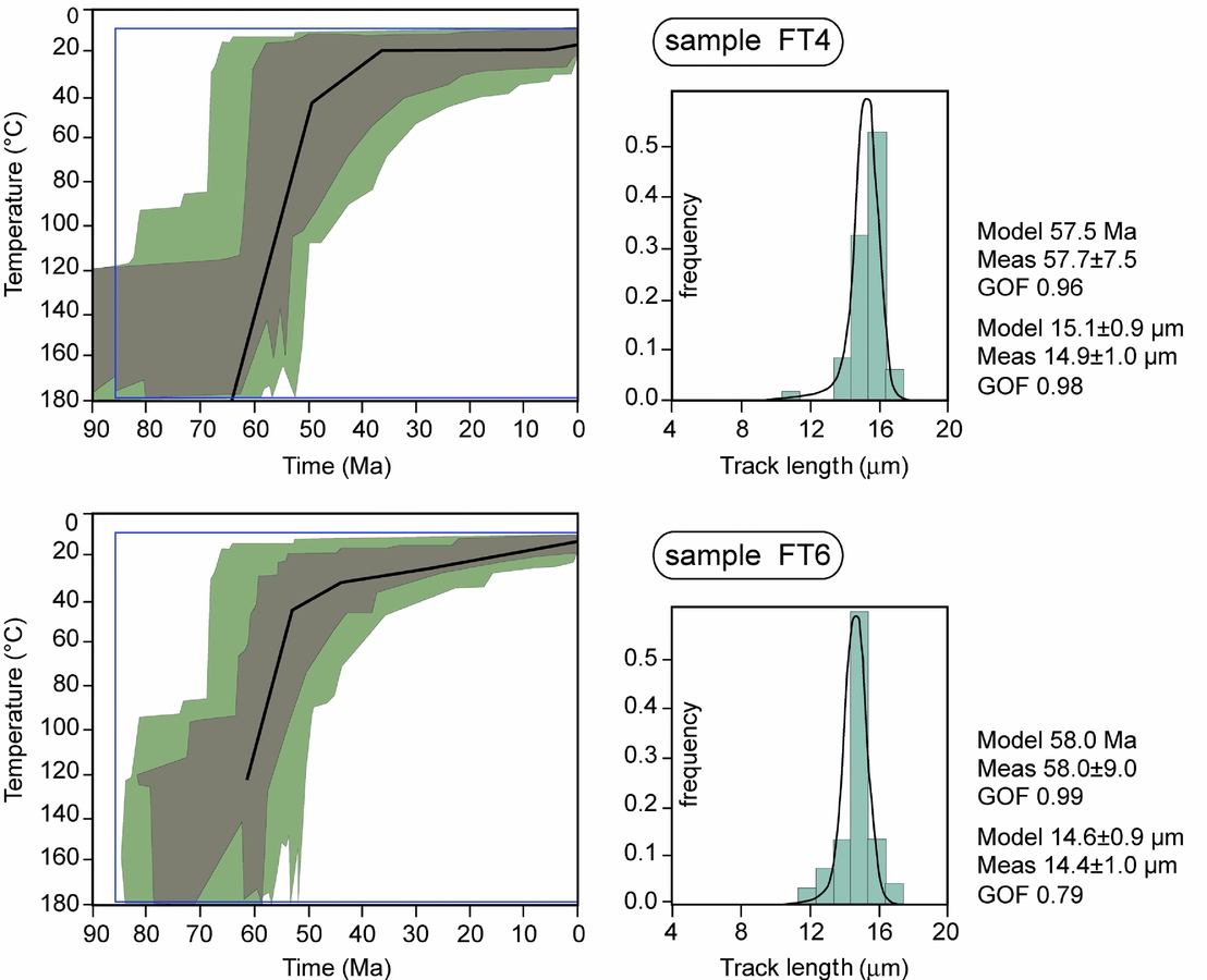
Figure 11. Profiles of apatite fission-track (AFT) time–temperature (t–T) models of samples FT4 (collected in the Saka Unit) and FT6 (collected in the Daday Unit) performed with the HeFTy program (Ketcham et al. Reference Ketcham, Carter, Donelick, Barbarand and Hurford2007). Brown envelopes represent a statistically good fit (statistical parameters > 0.50), whereas green envelopes represent an acceptable fit (statistical parameters > 0.05). The best-fit thermal path for AFT is shown in black. On the right, mean track length distributions (light blue) and the best-fit curves (black) are shown.
Thermal history reconstructions were performed using inverse modelling of the fission-track data (Gallagher, Reference Gallagher1995; Ketcham, Donelick & Donelick, Reference Ketcham, Donelick and Donelick2000; Ketcham, Reference Ketcham2005) with the HeFTy program (Ketcham et al. Reference Ketcham, Carter, Donelick, Barbarand and Hurford2007). The inverse modelling of the data resulted in a history of rapid cooling across the partial annealing zone (PAZ, between 60 °C and 120 °C) of the AFT system approximately between 65 and 55 Ma.
5. Discussion
5.a. The Daday Unit: a fragment of supra-subduction oceanic crust of Jurassic age
The collected data indicate that the Daday Unit consists of an assemblage of slices of both metasedimentary and metabasic rocks. The occurrence of boninitic and BABB-type signatures in the studied samples indicate that the metabasites in the Daday Unit are fragments of an intra-oceanic arc-basin system. However, to fully characterize the ophiolitic metabasic rocks from the Daday Unit, the geochemical data collected in the Daday Massif are joined with those collected by Sayit et al. (Reference Sayit, Marroni, Göncüoğlu, Pandolfi, Ellero, Ottria and Frassi2016) in the Daday Unit cropping out in the Tosya area (Fig. 1b). In this area, BABB-type signatures still exist, with Nb anomalies (Nb/Nb* = 0.3–0.6: Sayit et al. Reference Sayit, Marroni, Göncüoğlu, Pandolfi, Ellero, Ottria and Frassi2016, Fig. 5) encompassing the range observed in the Araç region. It must be noted, however, that the Tosya region comprises also E-MORB- and OIB-like samples, which are not found in the Araç area. The E-MORB-type samples are characterized by higher Th, Nb and LREE (light rare earth element) concentrations relative to N-MORB (ThM = 4.2–10.0, NbM = 2.2–4.3, LaM = 2.4–3.4) (Fig. 6). The OIB-type, which is represented by a single sample of alkaline composition, displays significant enrichment in incompatible elements and fractionated LREE/HREE patterns ((Ce/Yb)N = 9.2) (Fig. 6). The E-MORB-like characteristics may have been derived from an N-MORB source region with relatively low degrees of partial melting. Alternatively, an enriched source may have been involved, and mixing of melts deriving from such an enriched source and those from a depleted mantle may have occurred at various proportions to create E-MORB-like melts. The OIB-type signatures, on the other hand, require a predominant contribution of melts derived from an enriched mantle source. To summarize, the geochemical characteristics of metabasic rocks from the Daday Unit imply the occurrence of remnants of an ancient arc-basin system (Sayit et al. Reference Sayit, Marroni, Göncüoğlu, Pandolfi, Ellero, Ottria and Frassi2016). The E-MORB- and OIB-like signatures found outside the Daday Massif may also have been generated in the same arc-basin system (e.g. Leat et al. Reference Leat, Livermore, Millar and Pearce2000; Hickey-Vargas et al. Reference Hickey-Vargas, Savov, Bizimis, Ishii, Fujioka and Christie2006).
The metasedimentary rocks of the Daday Unit derive from a succession consisting of cherts, shales, siltites, quartz-arenites and limestones. Although their pristine relationships cannot be clearly reconstructed, the interfingering relationships between the micaschists and paragneisses indicate a primary association. The pristine relationship existing between the different lithotypes was observed outside the mapped area where actinolite-bearing schists (i.e. metabasalts) are found associated with meta-cherts and meta-volcaniclastic rocks (Fig. 12). These data indicate that the crustal section from which the metamorphic rocks of the Daday Unit derived was characterized by basic volcanic rocks of oceanic crust origin with cherts (and thin intercalation of volcaniclastic rocks) and topped by limestones (i.e. marble) grading upwards to shales and arenites, probably representing turbidite deposits (i.e. micaschists, fine- to coarse-grained paragneisses; Fig. 12)

Figure 12. Reconstruction of the hypothetical crustal section from which the metamorphic rocks of the Daday Unit derived and field pictures showing the pristine relationships between quartzites (i.e. meta-cherts), meta-volcaniclastic levels and actinolite-bearing schists (i.e. metabasalts) in the Tosya area. Hammer for scale is 27 cm long.
Since no palaeontological ages are available for the metasedimentary succession of the Daday Unit, its depositional age can be ascertained by the geochronological data. The finding in the paragneisses of detrital zircons of Early Jurassic age (Okay et al. Reference Okay, Sunal, Sherlock, Altiner, Tüysüz, Kylander-Clark and Aygül2013) and the Late Jurassic age of the D1 phase constrain the age of the metasedimentary rocks to Middle Jurassic time. On the whole, the succession from which the metamorphic rocks of the Daday Unit are derived can be described as an oceanic crust and related deep-sea sedimentary cover of Middle Jurassic age.
5.b. Pressure–temperature–time–deformation (P–T–t–D) path of the Daday Unit: tectonic underplating and subsequent exhumation during the Late Jurassic and Early Cretaceous time span
The rare findings of isoclinal F1 folds as well as the scattered occurrence of the relics of S1 foliation hamper the full reconstruction of primary features of the D1 phase. Thus, the significance of the D1 phase can be hypothesized only taking into account the P–T conditions estimated using the metamorphic mineral paragenesis that grew along the S1 foliation. Pressure and temperature estimates indicate that the D1 phase was acquired during lower blueschist-facies metamorphic conditions (T ≈ 220–420 °C, P ≈ 1.0–1.2 GPa) at a depth of ~ 35–44 km. 40Ar–39Ar dating on white mica indicates that this event occurred during Early Jurassic time (157.6 ± 3.4 Ma) (Fig. 13a). These data suggest that the D1 deformational phase was acquired at pressure-peak during the accretion of the Daday Unit to an accretionary wedge in a subduction setting.
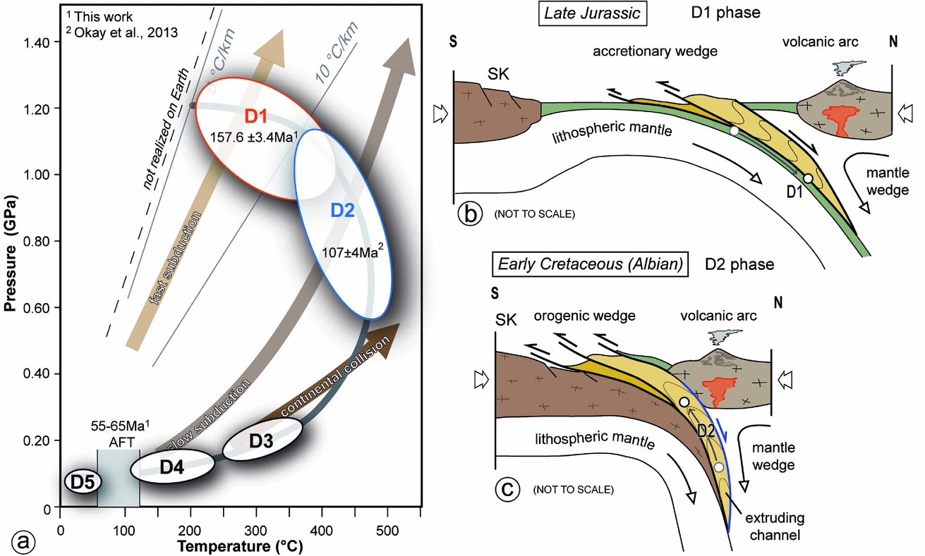
Figure 13. (a) Retrograde pressure–temperature–time–deformation (P–T–t–D) path proposed for the metasedimentary rocks of the Daday Unit in the Araç area. (b, c) Geodynamic reconstruction of the Intra-Pontide oceanic domain during Late Jurassic time (b) and Early Cretaceous time (c). See text for further explanations.
The D2 phase is characterized by tight to isoclinal F2 folds and by a pervasive S2 foliation that developed both as axial plane surface or as mylonitic foliation along the shear zones located at the boundary of each tectonic slice that show a general top-to-S sense of shear. Thermodynamic calculations conducted on chlorite–phengite pairs that grew in equilibrium along the S2 foliation indicate that the D2 phase was acquired during metamorphic conditions typical of greenschist facies – low-pressure epidote blueschist facies (Fig. 9; T ≈ 400–480 °C, P ≈ 0.55–1.1 GPa) at a depth of ~ 37–17 km (Figs 9, 13a). The age of the D2 phase can be tentatively determined according to the 40Ar–39Ar ages provided by Okay et al. (Reference Okay, Sunal, Sherlock, Altiner, Tüysüz, Kylander-Clark and Aygül2013) for the Martin Complex, corresponding in the study area to the Daday Unit. These authors obtained the age of 107 ± 4 Ma (Albian, Early Cretaceous) for fine-grained white micas grown along a pervasive foliation that can be tentatively interpreted as related to the D2 phase. The Daday Unit was so exhumed from a depth of ~ 44–35 km to ~ 37–17 km in a period of time of c. 50 Ma, implying a roughly mean vertical exhumation rate of ~ 0.25 mm yr−1 during Late Jurassic to Early Cretaceous times (i.e. Albian).
Since the boundaries between the different tectonic units as well as the boundaries between different tectonic slices within the Daday Unit are marked by the S2 foliation (the main foliation documented in the field), the stacking of metamorphic and non-metamorphic (Arkot Dağ Mèlange and Ayli Dag ophiolite Unit) units of the IPS zone in the Daday Massif probably started during the late stage of the D2 phase. The subsequent D3 phase produced a composite fabric acquired during ductile–brittle to brittle deformation regimes. The main structures are represented by low-angle thrusts with a top-to-the-S sense of shear and by F3 folds. The D3 thrusts promote and emphasize the imbrication of the Daday Massif nappe stack.
The open recumbent F4 folds and the low-angle normal faults produced during the D4 phase were originated from vertical shortening of pre-existing non-horizontal layers during an extensional tectonic phase due to the gravitational collapse of the over-thickened orogenic wedge (Froitzheim, Reference Froitzheim1992; Wheeler & Butler, Reference Wheeler and Butler1994). The brittle low-angle extensional shear zones produced during the D4 phase reworked the top-to-the-S thrusts produced during the D3 phase. These structures occurred at shallower structural levels (< 5–10 km of depth) and are sealed by the upper Paleocene – middle Eocene deposits of the inter-mountain Karabük–Kastamonu basin (Tüysüz, Reference Tüysüz1999; Hippolyte et al. Reference Hippolyte, Müller, Kaymakci, Sangu, Sosson, Kaymakci, Stephenson, Bergerat and Starostenko2010). In this reconstruction, the AFT ages of ~ 58 Ma (late Paleocene) may constrain the final stages of the D4 phase and the last episodes of uplift before the deposits of the inter-mountain Karabük–Kastamonu basin and the inception of NAF activity. The analogous ages obtained for the samples collected in the Daday Unit and in the Saka Unit indicate that the entire nappe stack was exhumed at the same time.
To sum up, the P–T–t–D path reconstructed for the Daday Unit shows a classic clockwise trajectory with very different maximum pressure and temperature conditions (Fig. 13a). The Daday Unit was buried reaching blueschist-facies metamorphic conditions (D1 phase) and then exhumed during progressive top-to-the-S shearing from deep (D2 phase) to shallow crustal levels (< 10–15 km of depth; D3 phase). The last step of exhumation occurred at shallower structural levels under an extensional tectonic regime induced by gravitational collapse. As a consequence, the D2, D3 and D4 phases were responsible for the metamorphic gaps existing between the Daday and Saka units and the Ayli Dağ ophiolite Unit and Arkot Dağ Mèlange and the large-scale crustal levels omission documented in the IPS zone nappe stack cropping out in the Daday Massif.
5.c. The post-collision evolution of the Intra-Pontide suture zone
The architecture of the Daday Unit acquired during the exhumation path (see section above) was sealed by the upper Paleocene – middle Eocene deposits of the inter-mountain Karabük–Kastamonu basin (Tüysüz, Reference Tüysüz1999; Hippolyte et al. Reference Hippolyte, Müller, Kaymakci, Sangu, Sosson, Kaymakci, Stephenson, Bergerat and Starostenko2010) and by middle Eocene volcaniclastic rocks and lavas (Keskin, Genç & Tüysüz, Reference Keskin, Genç and Tüysüz2008). The metamorphic and non-metamorphic units of the IPS zone and the post-collisional deposits were later deformed by the strike-slip or oblique high-angle fault systems related to the NAF zone. The F5 kilometre-scale folds, well documented in the massif north of Araç, may be interpreted as structures associated with the transpressional tectonic regime of the NAF zone (Fig. 13a) and, more in detail, they can be produced during the activity of the main fault system oriented ~ WSW–ENE (Ellero et al. Reference Ellero, Ottria, Marroni, Pandolfi and Göncüoğlu2015 a). The angle between the three systems of high-angle faults, the N-verging thrust and the F5 fold axes, in fact, is roughly compatible with the features expected from a theoretical model in a zone of dextral shear (e.g. Wilcox, Harding & Seely, Reference Wilcox, Harding and Seely1973) in which deformation is accommodated by both variably oriented compressional or extensional structures.
5.d. Constraints on the geodynamic evolution of the Intra-Pontide suture zone
The structural, metamorphic and geochronological data collected in the Daday Unit provide useful insights into the geodynamic history of IPS zone in the Central Pontides. The structures and the metamorphic data collected from D1 phase relics, coupled with regional data, indicate that starting in Middle Jurassic time (Okay et al. Reference Okay, Sunal, Sherlock, Altiner, Tüysüz, Kylander-Clark and Aygül2013; Çimen, Göncüoğlu & Sayit, Reference Çimen, Göncüoğlu and Sayit2016; Çimen et al. Reference Çimen, Göncüoğlu and Sayit2016), active subduction existed in the IPO basin (Fig. 13b). This subduction led to the underthrusting and accretion of the IPO crust covered by deep-sea sedimentary cover of Middle Jurassic age.
According to the reconstructed P–T path, the D2, D3 and D4 phases were achieved during the exhumation path from a depth of ~ 17–37 km to shallow structural levels (< 5 km of depth). These three phases may have been developed from Albian (age of the D2 phase) to late Paleocene times (i.e. immediately before the unconformable sedimentation of the deposits of the Karabük–Kastamonu basins). The continuous trend of the P–T estimates equilibria points moving from pressure-peak (D1 phase) to temperature-peak (D2 phase) conditions (Fig. 9) indicate that the exhumation was associated with a continuous and progressive decrease in pressure from ~ 1.20 GPa to ~ 0.55 GPa, and increase in the temperature up to ~ 480 °C. This exhumation path implies a change in the geothermal gradient from ~ 6–12 °C km−1 to ~ 9–24 °C km−1 during the D1 and the D2 phases, respectively. This change is consistent with a continent–arc collisional setting (e.g. Stern, Reference Stern, Kusky, Zhai and Xiao2010). In this setting, the exhumation of rock bodies occurred close to the volcanic arc where an increase in the heat flow occurs (e.g. in the Taiwan convergent margin: Lin, Reference Lin2000; Chi & Reed, Reference Chi and Reed2008) (Fig. 13c). This reconstruction is strongly supported by the identification of remnants of continental (Ellero et al. Reference Ellero, Ottria, Sayit, Catanzariti, Frassi, Göncüoğlu, Marroni and Pandolfi2015b ) and intra-oceanic (Aygul et al. Reference Aygül, Okay, Oberhansli and Ziemann2015 b) arc-related volcanism of Late Cretaceous age in the IPS zone.
The polarity of the subduction was probably northwards, according to the overall top-to-S sense of shear of the D2 and D3 phases and the location of the arc magmatism on the IZ continental margin during Middle Jurassic time (e.g. Gücer et al. Reference Gücer, Arslan, Sherlock and Heaman2016). In addition, the overall features of the D2, D3 and D4 phases show that the model for the exhumation of the Daday Unit can be acquired by extrusion in a subduction channel (e.g. Godin et al. Reference Godin, Grujic, Law, Searle, Law, Searle and Godin2006; Guillot et al. Reference Guillot, Hattori, Agard, Schwartz, Vidal, Lallemand and Funiciello2009 and references therein; Xypolias et al. Reference Xypolias, Iliopoulos, Chatzaras and Kokkalas2012). In the subduction channel, the exhumation of rock volume occurs through the activation of extensional detachments at the top and thrusts at the bottom of the channel during an overall compressional regime (Wheeler, Reddy & Cliff, Reference Wheeler, Reddy and Cliff2001; Reddy et al. Reference Reddy, Wheeler, Butler, Cliff, Freeman, Inger, Pickles and Kelley2003; Jolivet et al. Reference Jolivet, Faccenna, Goffé, Burov and Agard2003). In this framework, the Daday Unit is exhumed initially as a weak, ductile body (D2 phase) and then as a rigid but still deformable volume (D3 phase) in a time span running from the Albian to late Paleocene (Fig. 13). Also the D4 phase can be interpreted in the same framework, when the over-thickening of the orogenic wedge during the increasing collision produced an extensional tectonic regime driven by low-angle normal faults and folds with a sub-horizontal axial plane as detected in several orogenic belts (e.g. Froitzheim, Reference Froitzheim1992; Wheeler & Butler, Reference Wheeler and Butler1994; Marroni, Pandolfi & Meneghini, Reference Marroni, Pandolfi and Meneghini2004). The result of this process is the coupling of the Daday Unit with the non-metamorphosed Ayli Dağ ophiolite Unit and Arkot Dağ Mèlange at very shallow structural levels.
The pre-late Paleocene tectonic setting of the IPS zone has been strongly modified during Miocene time by the tectonics related to the NAF zone. Along the core zone of the NAF zone the units from the IPS zone are enclosed in lozenge-shaped domains bounded by strike-slip faults (Ellero et al. Reference Ellero, Ottria, Marroni, Pandolfi and Göncüoğlu2015 a), whereas far from the core zone, as in the Daday Massif, the pre-late Paleocene tectonic setting, even if strongly deformed by faults, thrusts and folds, can be still reconstructed.
6. Conclusions
The collected data indicate that the Daday Unit consists of a block-in-matrix assemblage derived from a supra-subduction-type oceanic crust and related deep-sea sedimentary cover of Middle Jurassic age. This setting was acquired during Late Jurassic time by tectonic underplating at a depth of 35–42 km leading to the development of blueschist-facies metamorphism (D1 phase). The following D2, D3 and D4 phases developed during the exhumation of the Daday Unit that occurred in a time span running from the Albian to late Paleocene. The D2 phase developed under greenschist – lower-pressure epidote blueschist facies, whereas the D3 and D4 phases are characterized by lower P–T conditions. The high geothermal gradient detected during the development of the D2 phase seems to be consistent with the inception of the exhumation during a continent–arc collision. On the whole, the transition from D2 to D3 and D4 phases indicates an exhumation of the Daday Unit from 37–17 km to uppermost structural levels (< 5–10 km of depth). During the D2 and D3 phases, deformation with a dominant top-to-S sense of shear developed, whereas the D4 phase is characterized by structures indicating extensional tectonics.
This picture suggests that the IPO basin was characterized by a subduction zone where the Daday Unit experienced underthrusting and accretion from Late Jurassic time and then exhumation, from Early Cretaceous up to Paleocene times. The exhumation probably occurred in a subduction channel active during an arc–continent collision. The result of this process is the exhumation of the Daday Unit joined to its tectonic coupling with the Ayli Dağ ophiolite Unit and Arkot Dağ Mèlange, i.e. the remnants of the shallower structural levels of the subduction system.
Acknowledgements
We thank Osman Parlak and an anonymous reviewer for the constructive criticisms that helped to improve the manuscript and Giovanni Capponi for the editorial work. The research has been funded by Darius Project (Resp. M. Marroni). This research also benefits from grants from PRIN 2008 and PRIN 2010–2011 Project (Resp. M. Marroni) and from IGG-CNR.
Supplementary material
To view supplementary material for this article, please visit https://doi.org/10.1017/S0016756817000176


