1. Introduction
Detailed studies of basaltic or basaltic andesite lava flows have been dominated by investigations at only a few volcanoes, for example, Hawaiian volcanoes (Soule, Cashman & Kauahikaua, Reference Soule, Cashman and Kauahikaua2004; Harris et al. Reference Harris, Favalli, Mazzarini and Hamilton2009; Ball, Pinkerton & Harris, Reference Ball, Pinkerton and Harris2008), Longquimay, Chile (Naranjo et al. Reference Naranjo, Sparks, Stasiuk, Moreno and Ablay1992) and Etna, Italy (Polacci & Papale, Reference Polacci and Papale1997, Reference Polacci and Papale1999; Calavari & Pinkerton, Reference Calavari and Pinkerton1998, Reference Calavari and Pinkerton1999; Guest et al. Reference Guest, Kilburn, Pinkerton and Duncan1987; Guest & Stofan, Reference Guest and Stofan2005; Bailey et al. Reference Bailey, Harris, Dehn, Calavari and Rowland2006). There is need to examine case studies elsewhere. Studies focused on lava flow emplacement dynamics can help volcanologists understand and predict the kinematics of lava flows (e.g. Pinkerton & Sparks, Reference Pinkerton and Sparks1976; Peterson & Tilling, Reference Peterson and Tilling1980; Kilburn, Reference Kilburn and Fink1990; Kilburn, Pinkerton & Wilson, Reference Kilburn, Pinkerton, Wilson, Mcguire, Kilburn and Murray1995; Polacci & Papale, Reference Polacci and Papale1997; Self, Keszthelyi & Thordason, Reference Self, Keszthelyi and Thordason1998; Self et al. Reference Self, Jay, Widdowson and Keszthelyi2008; Keszthelyi & Self, Reference Keszthelyi and Self1998; Cashman, Thornber & Kauahikaua, Reference Cashman, Thornber and Kauahikaua1999; Guest & Stofan, Reference Guest and Stofan2005). Estimates of lava velocity, direction and extent can aid in hazard mitigation.
Mount Cameroon (Fig. 1a, b) is one of the most active of Africa's volcanoes, with seven eruptions in the last 100 years. At Mount Cameroon, the well-exposed 1999 lava flows are not yet extensively colonized by vegetation and are well suited for field investigation of lava flow attributes. Aspects of the 1999 eruption have been documented previously (Suh et al. Reference Suh, Sparks, Fitton, Ayonghe, Annen, Nana and Luckman2003; Suh, Luhr & Njome, Reference Suh, Luhr and Njome2008). No detailed study has yet described the physical aspects of the 1999 lava flows, nor attempted to relate morphological features and flow structures to emplacement history and processes. This contribution documents the range of flow-types, morphologies and structures observed for the 1999 Mount Cameroon lava flows, and qualitatively assesses their development.
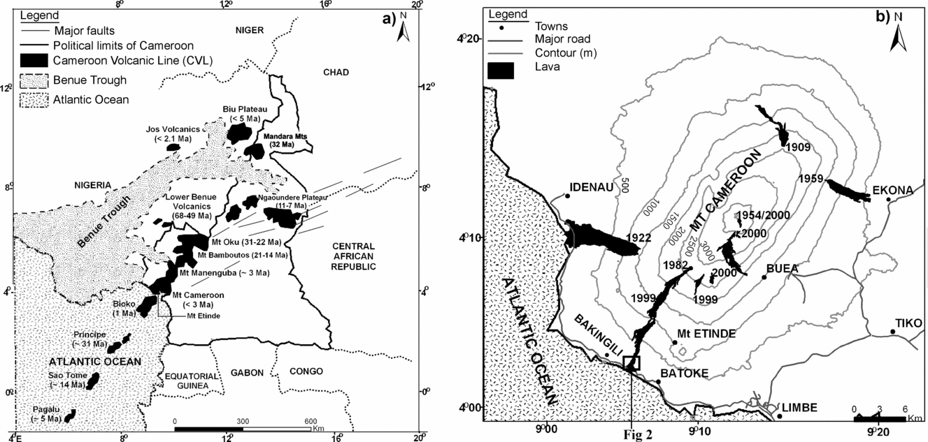
Figure 1. (a) Sketch map of the Cameroon volcanic line (CVL) showing the location of Mount Cameroon along this SW–NE-trending volcanic chain. (b) Contour map of Mount Cameroon displaying the 20th century lava flows (after Suh et al. Reference Suh, Sparks, Fitton, Ayonghe, Annen, Nana and Luckman2003). Location of Figure 2 at the distal end of the 1999 flow is indicated in the box outline.
2. Geological context of Mount Cameroon and the 1999 eruption
Mount Cameroon is a steep, lava-dominated volcano, situated at 4.20°N, 9.17°E (height: 4095 m a.s.l.) in SW Cameroon (Fig. 1b). Suh et al. (Reference Suh, Sparks, Fitton, Ayonghe, Annen, Nana and Luckman2003) estimated the volume of this volcano at 1200 km3. In plan form, Mount Cameroon is elliptical; 50 km long in a NE–SW direction, and 35 km wide in a NW–SE direction. The Mount Cameroon edifice surface is dominantly covered by basanite and hawaiite lavas and subsidiary fall-out tephra deposits. Recent K–Ar dates on seven mafic lava samples yielded ages between 2.83±0.11 and 0.00±0.09 Ma (Wandji et al. Reference Wandji, Tsafack, Bardintzeff, Nkouathio, Kagou Dongmo, Bellon and Guillou2009). Though weak Strombolian activity is observed, effusive eruption of lavas is the dominant phenomenon. Over 200 scoria cones can be identified, for example, on remote-sensing imagery, at Mount Cameroon, defining a NE–SW trend along the Cameroon Line, a 1600 km long linear volcanic zone that stretches from maritime Pagalu in the SW to Biu in NE Nigeria (Fig. 1a).
The Cameroon Line (Déruelle, Ngounouno & Demaiffe, Reference Deruelle, Ngounouno and Demaiffe2007 and references therein) is divided into two provinces: oceanic (dominantly basaltic with minor nephelinite, phonolite and trachyte lavas: Fitton, Reference Fitton, Fitton and Upton1987; Fitton et al. Reference Fitton, Kilburn, Thirwall and Hughes1983; Fitton & Hughes, Reference Fitton and Hughes1977; Halliday et al. Reference Halliday, Dickin, Fallick and Fitton1988) and continental (with a wider suite of rocks and age range, including felsic and basaltic lavas, and more silicic and alkaline plugs: Nono et al. Reference Nono, Deruelle, Demaiffe and Kambou1994; Marzoli et al. Reference Marzoli, Piccirillo, Renne, Bellieni, Iacumin, Nyobe and Tongwa2000; Ngounouno, Deruelle & Demaiffe, Reference Ngounouno, Deruelle and Demaiffe2000). The volcanic products are deposited on Tertiary sediments overlying a Precambrian crystalline basement (Toteu, Penaye & Poudjom Djomani, Reference Toteu, Penaye and Poudjom Djomani2004; Ngako et al. Reference Ngako, Njonfang, Aka, Affaton and Nnange2006), or intrusive syenites and granites younger than 70 Ma. Magma ascent in the NE section of the continental province was focused along a fracture zone (Poudjom Djomani et al. Reference Poudjom Djomani, Nnange, Diament, Ebinger and Fairhead1997).
Details of the 1999 eruption are presented in Suh et al. (Reference Suh, Sparks, Fitton, Ayonghe, Annen, Nana and Luckman2003). Following precursory earthquake swarms on 26–27 March 1999, the eruption occurred between March 28 and April 22 from two collections of vents at different elevations. The first set of vents, named site 1, opened at ~2807 m on March 28, and erupted both explosively and effusively. On March 30, a second set of vents, named site 2, opened at ~1545 m elevation. Site 1 lava flows have final dimensions of 3 km long, 30–120 m wide and with flow fronts 15 m high; Suh et al. (Reference Suh, Sparks, Fitton, Ayonghe, Annen, Nana and Luckman2003) estimated their volume as ~2.7 × 10⁶ m3. The lava effusion rates varied in the course of the eruption between 4.8 and 9.8 m3s−1. The main site 2 lava flow front extended about 10 km with dimensions ~400 m wide by ~10 m thick, indicating a lava volume of ~4 × 10⁷ m3 (Suh et al. Reference Suh, Sparks, Fitton, Ayonghe, Annen, Nana and Luckman2003). An average effusion rate of 40 m3s−1 was determined for the duration of the eruption from site 2. At site 2, over a dozen flow velocity measurements, ranging between 6.9 × 10⁻⁴ ms−1 and 5 ms−1, were recorded from 5 to 15 April 1999 (Fig. 2).

Figure 2. Map of the distal regions of the main site 2 flow-fields, near Bakingili, with flow velocities for different dates indicated. North is top of the figure.
The 1999 lavas are basanites (44–47% SiO2) with occasional hawaiites (Suh et al. Reference Suh, Sparks, Fitton, Ayonghe, Annen, Nana and Luckman2003; Suh, Luhr & Njome, Reference Suh, Luhr and Njome2008; Njome et al. Reference Njome, Suh, Sparks, Ayonghe and Fitton2008). The lava is porphyritic with olivine (8%), clinopyroxene (5%), plagioclase (3%) and titanomagnetite (1%) phenocrysts set in a fine-grained, often partly glassy groundmass (83%). Blocks of massive, non-vesicular lava have a mean density of 2592 kgm−3. Application of the olivine geothermometer (Roedder, Reference Roedder1974) infers a pre-eruptive temperature of 1166°C (±30°C). In contrast, residual hawaiite melt (Suh et al. Reference Suh, Sparks, Fitton, Ayonghe, Annen, Nana and Luckman2003), in equilibrium with more fayalitic microlites and phenocryst rims, gives an eruption temperature of 1042°C (±30°C), with measured temperatures of hawaiite lavas on Etna of 1070–1090°C (Pinkerton & Sparks, Reference Pinkerton and Sparks1976). Suh et al. (Reference Suh, Sparks, Fitton, Ayonghe, Annen, Nana and Luckman2003) measured field temperatures of 950–975°C 40 cm into the stagnant site 1 flow fronts (4 April) and 1000°C at the site 2 lava fronts ~10 km from the fissure (10 April), providing lower bounds on the lava temperature. With these temperatures and compositions, one can estimate lava viscosity. Using the empirical method of Shaw (Reference Shaw1972), a residual melt of hawaiite composition at between 1012°C and 1072°C yields a viscosity of between 145 and 320 Pas. Lava composed of 17% phenocrysts and 83% residual hawaiite has an estimated viscosity of ~320–710 Pas in the 1012 to 1072°C temperature range, whereas the composition of matrix glass (Suh et al. Reference Suh, Sparks, Fitton, Ayonghe, Annen, Nana and Luckman2003) yields viscosity for the residual melt of between 3.2 × 10⁶ and 106 Pas for the temperature range 950°C to 1000°C. Estimate of apparent viscosity of the 1999 lava flow fronts is in the order of 108 Pas from application of the Jeffreys equation to data on frontal speeds, thicknesses and slopes.
3. Lava flow morphology, field textures and structures: field methods
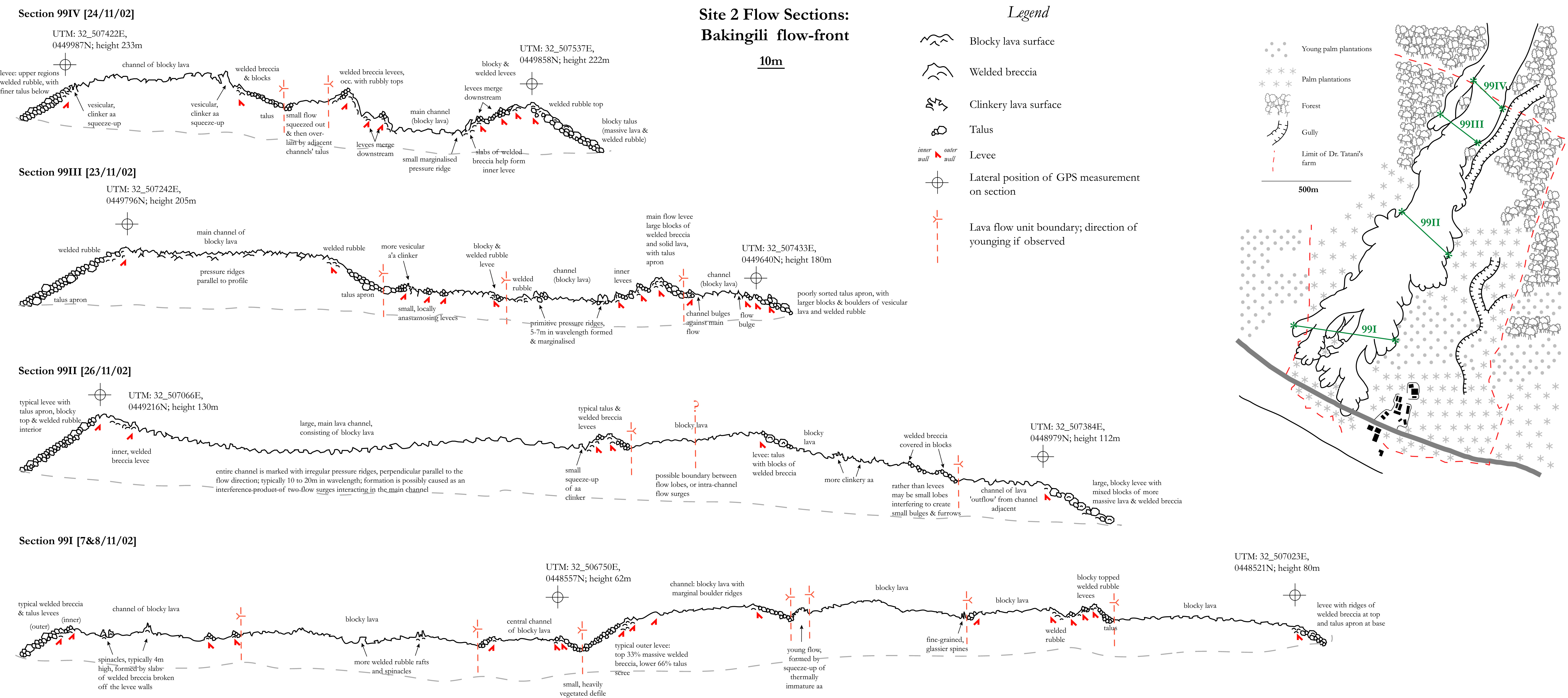
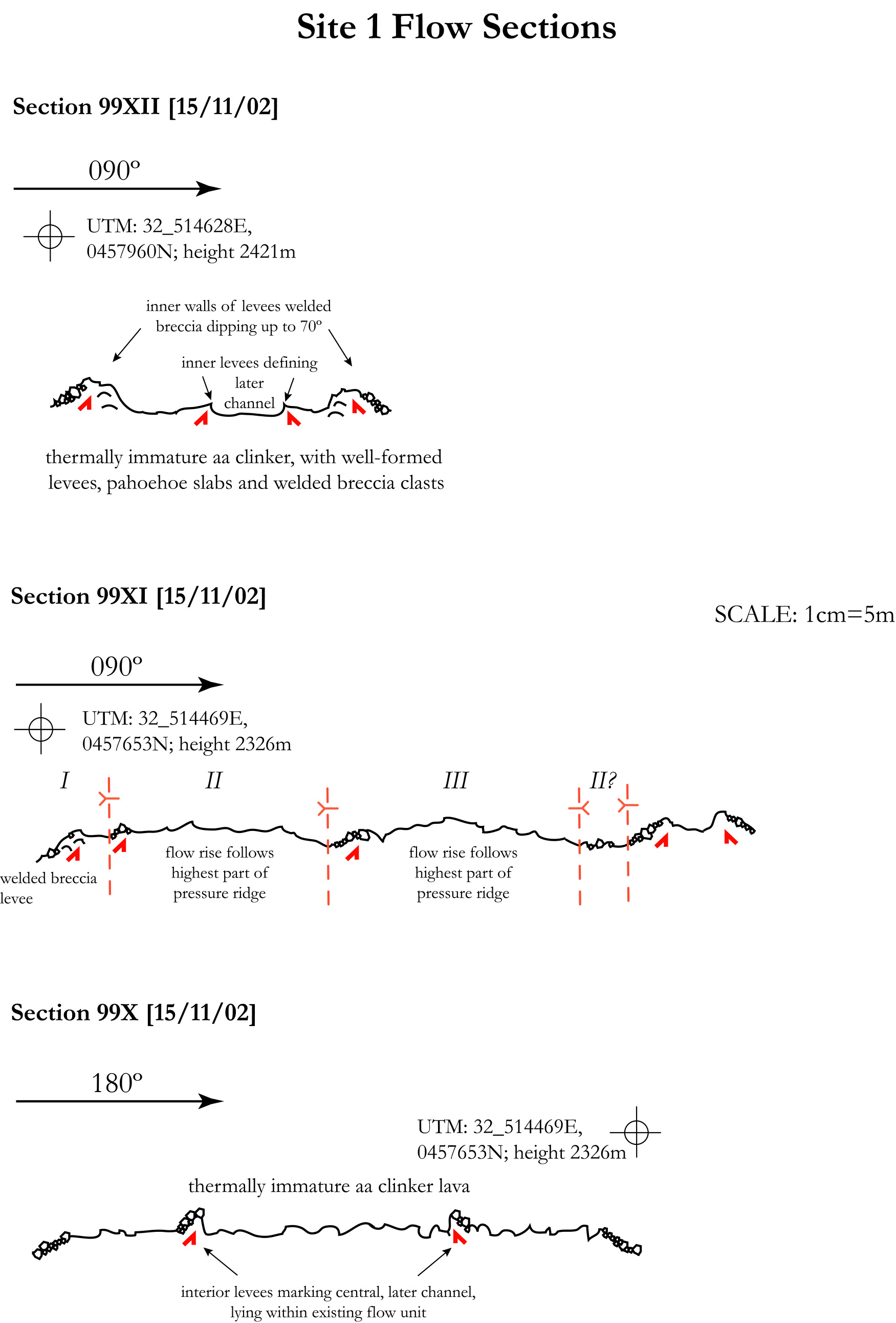
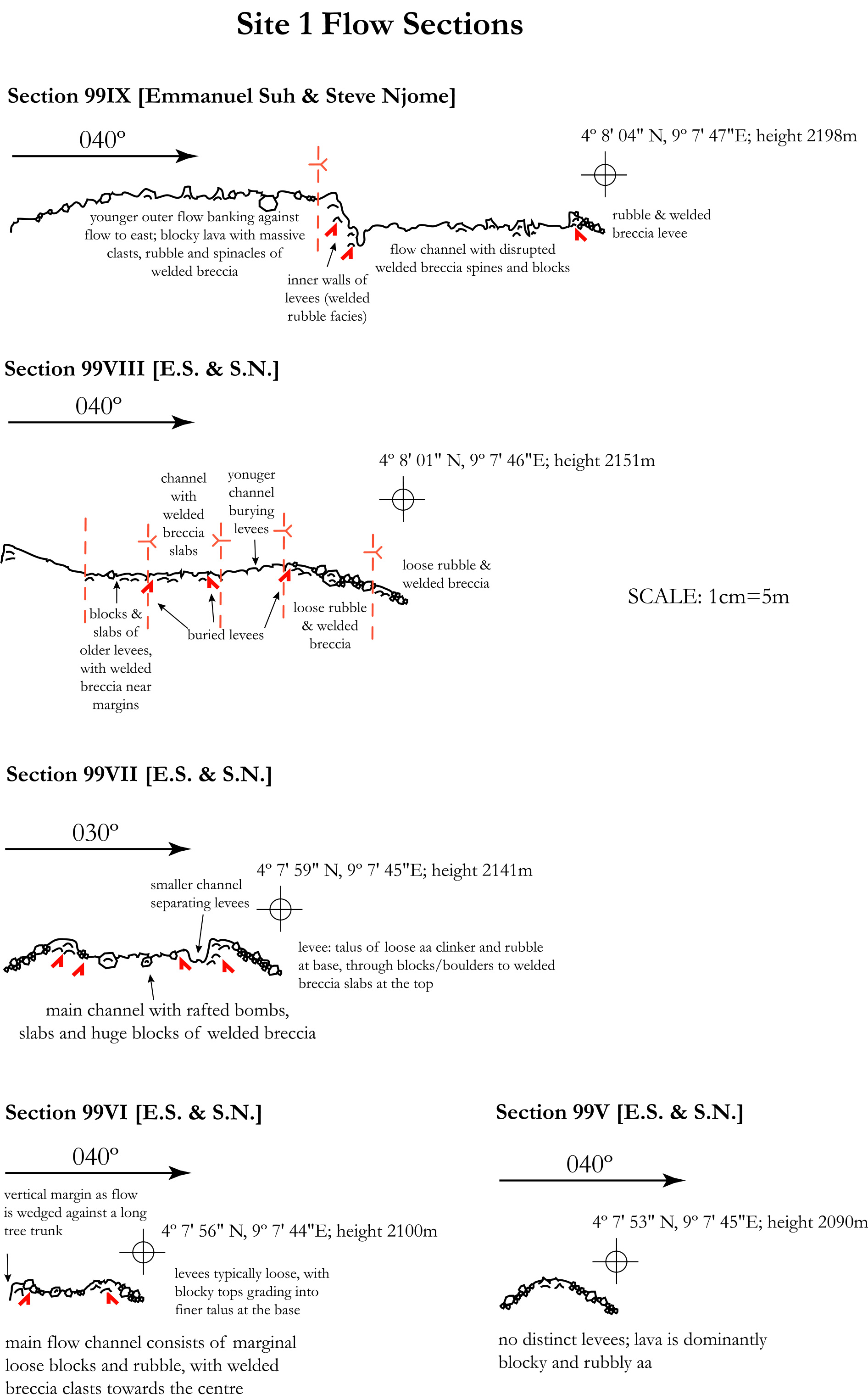
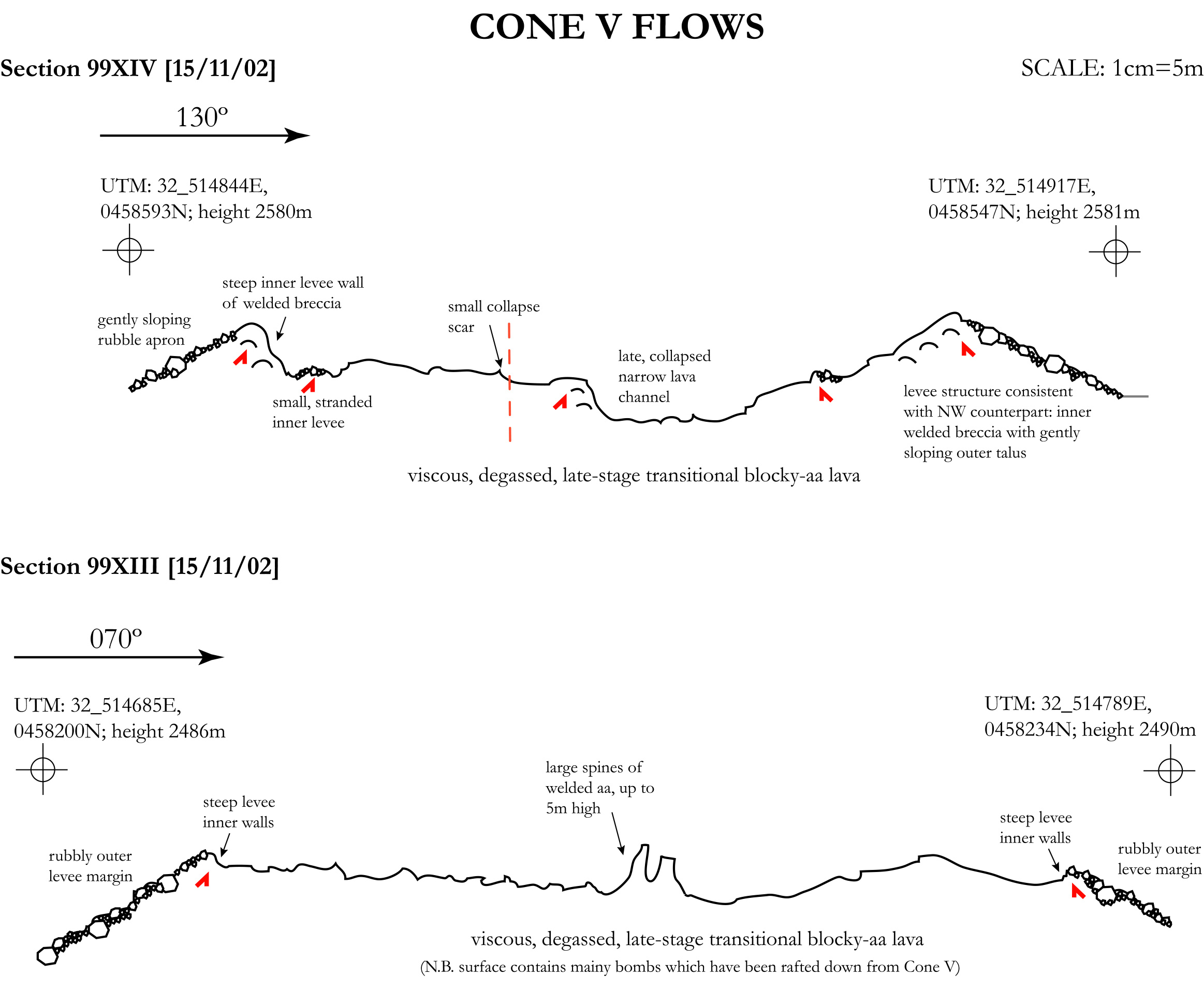
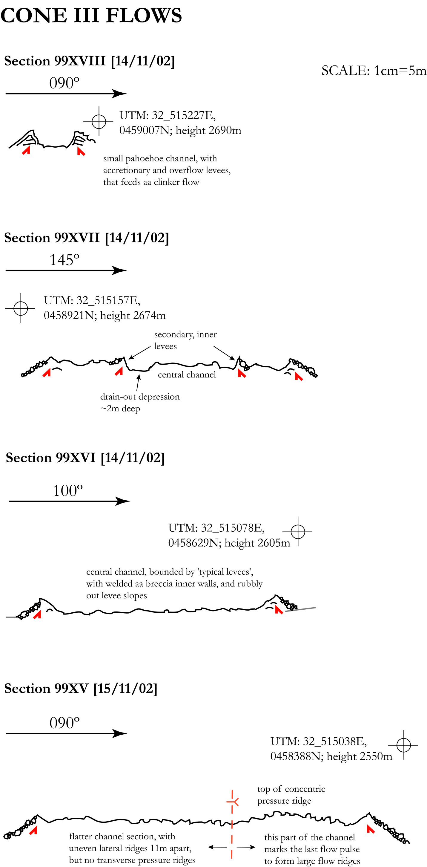
Transverse profiles (cross-sections from one flow margin to the other) were documented for 20 lava sections (online Appendix 1 at http://www.cambridge.org/journals/geo) by field surveys, using a tape measure, compass and an abney level. There are no accurate maps or DEM (digital elevation models) of the pre-eruption topography. Where possible, the contact with the underlying pre-eruption topography was evaluated using marginal levee-topography contact geometry.
4. Results and interpretations
4.a. Large-scale morphology: levees and channels
The lava cross-sections reveal that the flows have single (or multiple) channel(s) (Appendix 1 at http://www.cambridge.org/journals/geo), bounded by well-defined levees. An active channel is a stream of lava contained within marginal zones of static lava termed levees (cf. Harris et al. Reference Harris, Favalli, Mazzarini and Hamilton2009). Channel width varies greatly; proximal pahoehoe channels (Fig. 3a, b) are much narrower than distal blocky aa channels (some over 100 m wide, Fig. 3c). Successive sets of levees are commonly encountered as one passes from a flow margin to its centre and the final end-of-eruption channel surface (Fig. 3d). These stranded levee sequences are interpreted to represent an overall decrease in local flow rate over time. The outermost flow-unit bordering levees form first and, as the active flow region narrows and thickens, the marginal levees are constructed. The highest point of the outer levee marks the high-stand line for the lava. As this channel drains, lava leaves the outermost levee stranded. Internal levees can be formed through a variety of processes. Typically they represent subsequent flow pulses, or further inflation in the channel through rheological stiffening down-slope exerting a local back-pressure, which in turn leads to lava flow thickening (Harris et al. Reference Harris, Favalli, Mazzarini and Hamilton2009). The draining of this channel would expose another set of younger levees, and so the process can continue.

Figure 3. Typical large-scale features of the Mount Cameroon 1999 lava flows. (a) Proximal pahoehoe channel emerging from a near-source bocca, by the site 2 vents. (b) Accretionary levees developed in a small, proximal bocca-fed lava channel, near the site 2 vents. The central pahoehoe is flanked by clinker. The levees also display evidence of overflow activity, indicating a more complex, compound structure; hammer is ~40 cm long. (c) Distal blocky aa flow channel, near Bakingili. The central flow depicted is ~100 m wide. (d) Sequence of stranded levees. Photo is taken looking up flow with figure standing on an interior levee, bounding the main flow channel to the left. (e) Pahoehoe overflow levee with thin drape. (f) Thermally immature aa clinker features. The central region of pahoehoe is 50 cm at its greatest extent, and grades from a ropy facies into slabby, fractured pahoehoe downstream. The change to disaggregated aa clinker at the pahoehoe margins is abrupt.
Some profiles (Appendix 1 at http://www.cambridge.org/journals/geo) lack clear levees, and these are only a few metres (1 to 3 m) back from the flow front, corresponding with the zone of dispersed flow, or ‘flow toe’, as described by Lipman & Bank (Reference Lipman and Banks1987).
4.b. Small-scale morphology: textural characteristics of pahoehoe, aa and blocky lavas
4.b.1. Pahoehoe
Site 1 or 2 pahoehoe flows locally occur near the vents and are examples of thermally immature lavas (Fig. 3a, b). Having cooled little, they deform in a ductile fashion, forming ropes and folds on an otherwise relatively smooth surface (e.g. Fink & Fletcher, Reference Fink and Fletcher1978; Fink, Reference Fink1980). Surface samples consist of glassy, vesicular pahoehoe, with a finely drawn-out, bladed surface texture (Kilburn, Reference Kilburn and Fink1990). Blades are highly deformed, typically 2–4 mm in relief and contiguous for 1–2 cm, and commonly carry millimetre- and sub-millimetre-sized parasitic stubbly spines and knobs. Pahoehoe drapes (Fig. 3e) show a deformed, finely filamented and platy surface, with filaments of millimetre-relief changing direction over lengths of ~3 cm.
4.b.2. Clinker aa
Thermally immature aa displays typical irregular clinker appearance (Fig. 3f), analogous to the cauliflower aa of Kilburn (Reference Kilburn and Fink1990). The lava forms an irregular surface habit reminiscent of a ‘field of maltreated cauliflowers’, with aa forming small, irregular protrusions in the order of 1 to 10 cm in size, with similar inter-cauliflower distances, and a typical relief of 5 to 20 cm. The surfaces of cauliflowers and florets are composed of millimetre-sized spines that display a bladed (‘stiletto’) or stubby habit similar to Mt Etna lavas (Kilburn, Reference Kilburn and Fink1990).
4.b.3. Blocky aa
Thermally mature blocky aa is typically composed of a variety of clasts: abraded clinker, fractured angular blocks of massive lava or welded breccia fragments (Fig. 4a, b). The propensity of breccia facies and massive lava increases with increasing distance from the vent. Most large cauliflowers retain their characteristic morphology, having fractured into small blocks. Blocky aa varies between clast- and matrix-supported, and clasts may be angular, stubby or rounded. The matrix consists of fine to medium sand-grade material, and many clasts appear to be reworked granules of earlier breccias.

Figure 4. Detailed characteristics of block aa lavas of the 1999 Mount Cameroon flows. (a) Large blocky lava channel bordered by rubble levees, at the Bakingili lava fronts (looking upstream, NNE). Boulders in left foreground are ~50 cm across. (b) Upthrown slabs or spinacles of welded flow breccia/rubble, thrust out of the central region of a blocky channel of the distal site 2 flows near Bakingili. The men are ~170 cm tall.
4.c. Levee structure and texture
The 1999 flows of Mount Cameroon illustrate a diversity of levee types, and partial draining of some channels allows observation and analysis of their internal structure. These levees can be either ‘external’, that is, bounding a discrete flow unit (Fig. 5a), or ‘internal’, where they lie within the flow profile itself, as a secondary construct. Four archetypes of levees described by Sparks, Pinkerton & Hulme (Reference Sparks, Pinkerton and Hulme1976) are present, to varying degrees and combinations, in the 1999 flows.

Figure 5. Main levee types of the 1999 lava flows at Mount Cameroon volcano. (a) Outer rubble levee wall displaying typically loose (unconsolidated) angle-of-rest talus. The level of sorting in the marginal talus slopes varies considerably. The person is ~175 cm tall. (b) Accretionary levees developed in a small, bocca-fed lava channel. Hammer is ~40 cm long. (c) Steep inner wall of a rubble levee at the distal Bakingili flow fronts. The material here consists of a fine, matrix-supported welded breccia at the base, which grades upwards into a deposit of incipiently welded aa clinker and rubble. The clinkery breccia displays several ‘standlines’, typically 10 cm apart, interpreted as levee–channel interactions in response to changing flow level. The welded clinker grades into a less consolidated breccia richer in fines, and ultimately into a clast-rich rubbly top. Hammer is ~40 cm long.
4.c.1. Initial levees
Initial levees (static lava due to passage of the parental flow: Pinkerton & Sparks, Reference Pinkerton and Sparks1976; Lipman & Banks, Reference Lipman and Banks1987) are rarely preserved. They were observed to form on Mount Etna (Pinkerton & Sparks, Reference Pinkerton and Sparks1976), but were always destroyed by subsequent levee-forming processes. Naranjo et al. (Reference Naranjo, Sparks, Stasiuk, Moreno and Ablay1992) described well-preserved initial levees composed of massive andesite lava at Lonquimay volcano, Chile. The greater shear rate and high flow velocities of the Cameroon basalts compared to the low effusion rate Etna lavas studied by Pinkerton & Sparks (Reference Pinkerton and Sparks1976) lead to a different dynamic regime. Initial, incandescent visco-plastic levees on Mt Cameroon cool rapidly and fracture. Furthermore, the welding of marginal clinkers or actions of localized flow surges can overprint them with an ‘accretionary’ or ‘overflow’ character. Rarely, the emptying of both proximal and distal channels reveals massive lava on internal levee walls, underlying areas of welded breccia, clinker or overflow drapes. Such material is typically striated, and hence represents remnants of initial levees.
4.c.2. Accretionary levees
Accretionary levees are commonly preserved (Fig. 5b), and many have outwardly sloping inner walls (Fig. 5c). While the upper portions of the levees are welded clinker, more solid lava lies below the accretionary structures, with pahoehoe overflows draping them. Polacci & Papale (Reference Polacci and Papale1997) describe long undulations (with axial trace parallel to flow direction) in the near-bocca flows of Mt Etna, wherein the marginal clinker overlies solid lava ridges.
4.c.3. Rubble levees
Rubble levees (Fig. 5a) are composed of highly brecciated clinker and blocks, which can be loose, packed or commonly welded. Typically the levee will display two distinct parts: a more gentle outer slope (Fig. 5a) and a steeper inner wall (Fig. 5c). These sectors and their characteristic facies are shown in Figure 6. The lower outer slopes of external (flow bounding) levees are composed of loose, unconsolidated talus (Figs 5, 6). The size of the material varies from sub-millimetre-sized coarse sand, through granules and small blocks, to larger blocks and metre-sized boulders. Clasts are typically subangular to rounded, and the whole deposit is moderately to poorly sorted. There is typically a slight decrease in mean grain size down the outer levee. The upper portion of the outer slope is composed of welded clinkery rubble and breccia (Fig. 6). This material is dominantly the same facies as is seen on the inner wall: it may be solid, fractured or wholly disaggregated into large blocks. Where solid, it typically stands out above the lower talus apron at slopes of 45° to 60°, well above the angle of rest. This ‘outer top’ welded rubble facies may account for 10 to 40% of the outer slopes’ length; a mix of 66% talus and 33% welded breccia is typical. The welded breccia is typically overlain at the top by poorly sorted, unconsolidated angular blocks of rubble and massive lava. Such material is typically coarser (>10 cm across) and more angular than the outer levee talus.

Figure 6. Typical rubble levee geometry and structure of the 1999 lavas. This sketch shows the various textural facies and their spatial occurrence in typical rubble levees.
Below the above-described blocky top is a section of blocky, unconsolidated breccia, fining downwards. In some levee walls, this material grades rapidly into a poorly sorted, matrix-supported breccia, with partial, incipient welding (Fig. 6). These facies are similar to the basal breccia of Naranjo et al. (Reference Naranjo, Sparks, Stasiuk, Moreno and Ablay1992), but display a far greater variety of clast size and heterogeneity. The degree of welding varies greatly, with some blocks and rubble held in place by little more than a semi-consolidated sandy matrix.
Our observations (Figs 5, 6) suggest that the loose talus component of rubble levees is less significant than originally envisaged by Sparks, Pinkerton & Hulme (Reference Sparks, Pinkerton and Hulme1976). The levees are predominantly composed of partly to densely welded breccia and clinker, and some contain a massive core.
4.c.4. Overflow levees
Overflow levees are observed in near-vent or bocca flows and they are defined by thin pahoehoe drapes that cover existing initial or accretionary levees (Fig. 3e). The drapes are usually 15–30 cm thick and only travel approximately 2 to 3 m down existing levee slopes.
4.d. Lava channels
The geometry and morphology of channels display a strong variance between proximal and distal channel facies as the character of levees varies according to proximity to the bocca or vent. Most channels experienced repeated episodes of filling, inflation and drainage.
4.d.1. Pahoehoe channels
Proximal pahoehoe channels occur by the site 1 and site 2 vents, and at related boccas (Fig. 3). Bounded by initial, accretionary or overflow levees, pahoehoe channels are typically narrow (<2 m wide at site 2, ~6 m wide at site 1), and relatively thin, 15–30 cm thick. The surfaces of these proximal channels commonly are zoned with a central region of ropy or slabby pahoehoe, bordered by heavily sheared aa clinker margins (Fig. 3f). The central, ropy pahoehoe is typically no wider than 50 cm in a channel ~2 m wide. To either side there is an abrupt transition from pahoehoe into variably disaggregated clinker. The proximal ropy pahoehoe facies grades into slabby, fractured pahoehoe 10 to 15 m downstream.
4.d.2. Aa channels
Aa channels (Fig. 7) display a surface morphology dominated by scoriaceous and classic clinkery aa (e.g. Macdonald, Reference Macdonald1953; Lipman & Banks, Reference Lipman and Banks1987; Kilburn, Reference Kilburn and Fink1990). The channel surface comprises a highly irregular form of variably spinose, jagged, scoriaceous and/or roughly angular lava. The clasts can be wholly loose and disaggregated, welded or massive and deeply rooted into the flow interior (Jaggar, Reference Jaggar1930). Typically, clinkers are 0.02 to 0.5 m across, and overlie more massive lava interior (as seen by Macdonald, Reference Macdonald1945). Aa channels are typically accompanied by accretionary or rubble levees. Whereas pahoehoe is usually characterized by a single, clearly defined channel, distal aa channels commonly possess a hummocky appearance.

Figure 7. Aa channel from site 1 flow. The channel surface is composed of highly irregularly formed, variably spinose, jagged and scoriaceous clinkers of aa, 1–50 cm in diameter.
4.d.3. Blocky aa channels
These channels are exemplified by the most distal 1999 flow front (hereafter referred to as the Bakingili flow front; Fig. 4), with a series of interdigitating flow lobes outlining a flow field ~500 m wide at its greatest lateral extent. In contrast to the aa flows, the surface is unconsolidated, consisting of angular to rounded blocks of massive lava and welded breccia (0.1–2 m). Occasional rafts of welded breccia up to 4 m high thrust out through the surface rubble (Fig. 4b). The transition from clinkery aa channel surfaces to blocky aa is gradual. Clinker surfaces form as hot visco-plastic lava wells up between fractures or existing aa cauliflowers, or form as consolidating clots in more incandescent fluid flows (e.g. Macdonald, Reference Macdonald1953; Peterson & Tilling, Reference Peterson and Tilling1980; Lipman & Banks, Reference Lipman and Banks1987; Kilburn, Reference Kilburn and Fink1990). The clinker clasts are further milled and fragmented after formation. As aa surfaces develop and thermally mature, the underlying lava cools to the extent that it becomes a brittle solid; deformation subsequently results in fragmentation of the cooled surface region to form blocks.
4.e. Compression-induced structures
4.e.1. Pahoehoe ropes
Pahoehoe ropes are common in proximal regions (Fig. 3a). Twenty well-formed ropes present in a 2 m section imply a mean wavelength of 10 cm. The ropes typically display amplitudes of 5 cm on average (to a maximum of 10 cm). Ropes are compressive folds developed on still ductile cooled surfaces (Fink & Fletcher, Reference Fink and Fletcher1978; Fink, Reference Fink1980; Gregg, Fink & Griffiths, Reference Gregg, Fink and Griffiths1998).
4.e.2. Pressure ridges
Pressure ridges are exposed as rubbly linear hummocks, contiguous over distances ranging from a few metres to several tens of metres, displaying an orientation which varies from parallel to the channel sides to perpendicular to the flow direction along the channel centreline (Fig. 8a, b). They are commonly observed following a reduction in slope. A decrease in the angle of slope underlying a site 1 flow (Fig. 8a), from 17° to 6°, produced three well-developed transverse pressure ridges, with amplitudes of 0.6, 1.3 and 1.5 m, and average wavelength of 8.2 m. The side arms of the ridges slope at ~24°.

Figure 8. Main types of pressure ridges of the 1999 Mount Cameroon lava flows. (a, b) Pressure ridges in a site 1 transitional blocky aa channel (the person leans against one ridge, with crests of three ridges highlighted). Average structure wavelength is 8.2 m; photo looking upstream.
4.e.3. Squeeze-ups
Squeeze-up features, consisting of more thermally immature lava pushed through the solid/blocky flow carapace, are commonly observed, particularly in the blocky aa flows near Bakingili where a prominent ridge-like lobe of clinker aa ~5 m wide squeezes out between two adjacent lobes of blocky aa (Fig. 9a, b). The ridge's structure consists of a spinose, vesicular clinker aa overlying a core of solid massive lava. This lava displays well-developed lineations: near-horizontal striations in the flow direction, and sub-vertical, shallow tensile fractures a few centimetres deep. Eruptional visual evidence states that the blocky aa lobes were emplaced first, and the clinker squeezed out of the gap between them as the flow advanced.

Figure 9. Squeeze-ups compressive features of the 1999 Mount Cameroon lava flows. (a) Ridge-like squeeze-up of clinkery aa emplaced between two adjacent lobes of blocky lava, in the site 2 distal flow region, near Bakingili. Irregular, spinose clinker overlies a massive avesicular interior. Hammer is ~40 cm long. (b) Closer view of (a) showing thermally immature clinker-topped aa squeeze-up ridge. Massive, poorly vesiculated lava forms the main body of this feature and displays two well-developed lineations. fine near-horizontal striations parallel to the flow direction; and shallow, sub-vertical fractures typically a few centimetres deep. About 25 cm of hammer handle is visible.
4.e.4. Flow fronts
Flow fronts of more thermally immature aa flows comprise poorly sorted (5–100 cm), occasionally welded clinker, with large cauliflowers and finer abraded and brecciated clasts. These less-developed aa flows have heights of up to 1 to 2.2 m. The most distal thermally mature blocky aa flows develop highly irregular, poorly sorted blocky fronts (Fig. 10a, b, c), with a significant level of fine sand and dust. Large rafts and spines of welded breccia and massive lava are common, thrusting out of the talus and locally increasing the slope of the front, and supporting frontal heights of between 12 and 20 m.

Figure 10. Principal characteristics of the lava flow fronts. (a) Site 1 aa flow front, consisting of a poorly sorted, partially disaggregated mix of clinkers, welded clinkers, large aa ‘cauliflowers’ (terminology after Kilburn, Reference Kilburn and Fink1990) and finer brecciated material. The height of this small, thermally immature flow front is 1.7 m; hammer length is ~45 cm. (b) Aa flow front, more thermally mature than that in (a). This small lobe from a blocky lava flow has developed a greater proportion of welded, rubbly material than superproximal aa. The men are ~170 cm tall. (c) Flow front of a thermally mature Bakingili blocky flow that had overridden the Limbe–Idenau highway, typically composed of large rafts of welded rubble and a highly abraded fine talus.
5. Discussion
5.a. Mega-features
The 1999 lavas display a wide variety of morphologies, spanning the whole range of commonly observed basaltic lava features. Field structures vary strongly according to proximity to vent, underlying topography and local flow evolution. Even the most simple of near-vent or bocca channel sections tends to display two types of lava and three types of levees, and distal flow portions are more complex. The lavas were emplaced onto a landscape of varying relief and vegetation. Proximal site 1 flows were extruded from vents onto gently sloping (~12°) montane savannah, blanketed by recent ash or older flows. Burial of older lava was common, but older topographic features did not affect proximal flow evolution. The site 2 flows erupted at a lower altitude, closer to the upper limit of montane rainforest, and are more strongly guided by topography, forming several valley-fill sections closer to the vents.
The processes forming the above-described, large-scale levee sequences result from interplay of flow conditions and parameters, including the source flux and its fluctuation, the rheological stiffening at the downstream flow-front, local outbreak-focused drainage, and heterogeneous channel flow regimes. With regards to lava profiles, those on steeper slopes preserve clear channel structures and single, as opposed to compound or multi-channel, flow units (Appendix 1 at http://www.cambridge.org/journals/geo). As slope decreases, lava is more able to spread laterally. Ponding typically occurs at sharp reductions in slope, in wells and rifts in the topography, and behind a stagnant flow front.
5.b. Lava surface types
Lava surface characteristics are varied according to the thermal maturity of the flow surface itself (Naranjo et al. Reference Naranjo, Sparks, Stasiuk, Moreno and Ablay1992). When erupted from a vent or bocca, cooling rapidly changes the surface regions of the lava from an incandescent fluid with increasing levels of plasticity to a cooled, brittle solid (Ball, Pinkerton & Harris, Reference Ball, Pinkerton and Harris2008). If the flow ceases motion before the surface becomes sufficiently cooled to deform by semi-ductile or brittle mechanisms then smooth pahoehoe surfaces are preserved. With further cooling and crustal thickening, deformation can no longer be accommodated in a ductile manner, and consequently lava surfaces tear, disaggregating first into slabs and rafts, then into clinker, and ultimately into angular blocks.
With cooling, groundmass microlite content increases and crystal–fluid and crystal–crystal interactions become more frequent. As this process continues, there is a gradual transition from ductile to brittle behaviour. It is during this transitional process that aa lava surfaces form (Moore, Reference Moore1987; Kilburn, Reference Kilburn and Fink1990; Rowland & Walker, Reference Rowland and Walker1990; Jaggar, Reference Jaggar1930, Peterson & Tilling, Reference Peterson and Tilling1980). In laminar flow the central region of the channel moves faster than the flow margins where shear is highest. Thus lava surfaces in the centre have experienced less cooling and less shearing than lava surfaces at the channel margins (Flynn & Mouginis-Mark, Reference Flynn and Mouginis-Mark1994; Bailey et al. Reference Bailey, Harris, Dehn, Calavari and Rowland2006). As a consequence, the flow centre can remain as pahoehoe, whereas the cooler and more sheared margins develop an aa clinker texture as illustrated in Figure 3a.
As lava evolves further, and develops a cooler, thicker crust, the tensile and shear stresses that build in a flow are accommodated by brittle failure. As the lava becomes more thermally mature the depth of solid–ductile transition increases, and the most thermally mature lavas are produced, with surface analogous to the flows of Macdonald (Reference Macdonald1953). Although blocky flows are commonly associated with the more viscous lavas of andesite and rhyolite flows (Macdonald, Reference Macdonald1953), primarily as a function of their slower emplacement times (and hence opportunity to thermally mature), they are also witnessed at long-lived basaltic flows (e.g. Booth & Self, Reference Booth and Self1973; Keszthelyi & Self, Reference Keszthelyi and Self1998; Harris et al. Reference Harris, Favalli, Mazzarini and Hamilton2009 and references therein), as documented in this study. The upper surface of the flow as well as an increasing fraction of the marginal flow interior deform more as a granular flow, with blocks milling, fracturing and rearranging to accommodate channel movement.
5.c. Implications of levee structures: modes of formation
Irrespective of their post-eruption propensity, initial levees form a protostructure that can be masked or altered by subsequent levee-building processes (Harris et al. Reference Harris, Favalli, Mazzarini and Hamilton2009). Hulme (Reference Hulme1974) argues that lateral spreading is eventually inhibited by the development of non-Newtonian properties in the marginal lava with the basal shear stress falling below the yield strength. Following the development of initial levees, the focus of flow down a channel produces high rates of shear at the levee–channel interface. The newly erupted lava is sheared too quickly to form fluid pahoehoe, and instead accommodates deformation in a plastic manner, forming small, irregular clinkers (Peterson & Tilling, Reference Peterson and Tilling1980; Keszthelyi & Self, Reference Keszthelyi and Self1998). With the generally parabolic profile of the flow kinematics, modified by an added lateral component supplied by a typically convex-upwards surface, hot and plastic marginal clinkers are accreted together along the initial levee margins, further developing the levee structure.
Sparks, Pinkerton & Hulme (Reference Sparks, Pinkerton and Hulme1976) argued that accretionary levees form through a ‘steady, slow rise of lava level’. Such an increase may arise from an increase in the effusion rate, or from the cooling of more distal regions, especially the flow front. As already discussed, the slower-moving channel margins will display the effects of cooling preferentially to the more mobile interior. The two factors promoting accretion are both greatest at the upper portions of the channel sides: shear, aiding the smearing and consolidation of clinkers, and cooling, which promotes the solidification and stabilization of the levee. Successive rises in flow level will thus accrete material from the channel, and build outwardly sloping inner walls unless a flow surge or blockage downstream causes a more rapid rise, in which case overflows will likely occur (Harris et al. Reference Harris, Favalli, Mazzarini and Hamilton2009). There is often considerable interplay between initial, accretionary and overflow levee-building processes. In the 1999 Mount Cameroon lava flows, pahoehoe overflows overlie much of the welded clinker, indicating a later, possibly surge-fed genesis. Areas of welded material overlie more massive lava, suggesting the accretionary constructs post-date, or are contemporaneous with, the initial levee-forming lava.
Rubble levees begin to form in response to the back-pressure created by the rheologically stiffened flow front (Calavari & Pinkerton, Reference Calavari and Pinkerton1998; Bailey et al. Reference Bailey, Harris, Dehn, Calavari and Rowland2006). As the front advances, the rheologically and texturally zoned material is pushed aside by the caterpillar motion of the cooled surface, aided by the mobile fluid interior (Peterson & Tilling, Reference Peterson and Tilling1980; Fig. 11a, b). This new flow front soon cools and brecciates, and is itself marginalized by more thermally immature material or, more commonly, the thermally developed flow surface, building marginal rubble levees which display a gradation from external rubble, through welded clasts into a sluggish visco-plastic interior. These structures are modified by the subsequent passage of warmer channelized lava. Additional material is provided by the transport of blocky material from the channel to the levee margins, and occasional ‘blocky overflows’ (similar to fluid overflow levees, only using clastic material). For the inner walls of the rubble levees, margin shear and lateral channel pressure will erode initially fractured material so that it degrades in size, and sorts through to the basal regions of the shear zone, forming an incipiently welded fine basal breccia. As downflow rheological changes cause a back-pressure to build up, resulting in flow thickening, and local narrowing of the channel as a function of cooling similarly occurs, the flow channel will inflate, and flow level will rise. The upper surface will accommodate this movement by blocky avalanching, further developing and thickening the angle of talus that develops on the levee outer slopes. Along the inner margin, the rise in level effectively raises the level of the hot, interior portion of the flow. This serves to weld further the initial rubble and breccia that accumulated, giving the levee stability, and also welding newer, warmer clinker to the wall, in a manner similar to that displayed in an accretionary levee. When the lava reaches its maximum height, upwards building of the levees ceases. The material deposited at the top represents the youngest material accrued to the levee, consisting of cool, thermally mature blocky lava, deposited from the channel. A subsequent decrease in lava level will strand this material here and result in the rubble levee profile described at Mount Cameroon.
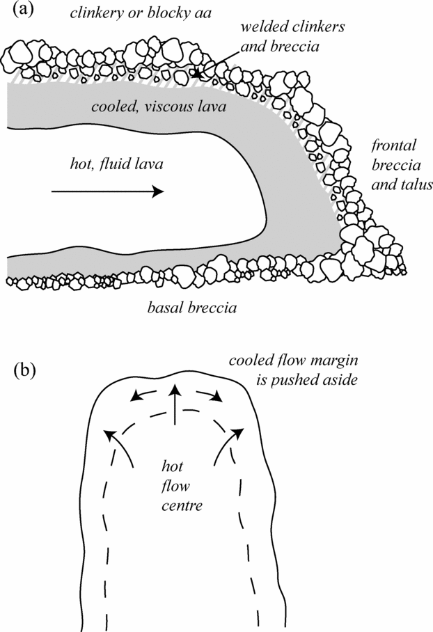
Figure 11. Structural and thermal zonation in blocky aa flows. Cooling causes initially Newtonian or weakly pseudoplastic material to stiffen, become increasingly non-Newtonian and ultimately cease behaving as a fluid, but pass into a regime of solid mechanics and brittle failure. As cooling is focused along the flow margins, and flow-top material is deposited at the flow toe by a caterpillar-like motion, frontal regions produce a flow profile similar to (a). While the core can deform in a ductile manner, the marginal carapace consists of torn clinkers and fractured blocks and rubble. The advance of the flow produces continual milling and further fracture; the high basal rates of shear and ‘conveyor belt’ style of advance of the flow front produce a similar layer of autobrecciated material on the flow base. As flow toe advances (b), the surface clinker or blocky aa pushes aside the sluggish, partially brecciated margins, whose structure forms the proto-rubble levees that are further developed by adjacent channel motion.
Overflow levees are generally formed following a flow surge or pulse, or a gradual rise in the lava level as a function of down-slope cooling (Sparks, Pinkerton & Hulme, Reference Sparks, Pinkerton and Hulme1976; Bailey et al. Reference Bailey, Harris, Dehn, Calavari and Rowland2006). They are generally thin and have limited extent, indicating they were supplied by pulses of short-lived liquid lava (Harris et al. Reference Harris, Favalli, Mazzarini and Hamilton2009). Both pahoehoe drapes and aa overflows are relatively common in the 1999 flows, occasionally in the same flow, with pahoehoe most likely signifying a vent-induced surge of hotter, less thermally mature lava, and aa depicting a back-pressure-derived rise in marginal clinker. Aa overflows at Etna have been interpreted as being due to localized channel blockages. Also, the pahoehoe drapes for the 1999 lavas extend no more than 15 m from the channel and are usually <1 m thick. This ties with observations at Etna (Bailey et al. Reference Bailey, Harris, Dehn, Calavari and Rowland2006) and underlies the unsteady nature of flow within the channel.
5.d. Significance of compressive structures
Lava flows develop compressive stresses during emplacement as a result of slower speeds at the front than in the flow behind (see also Lister, Reference Lister1992). As lavas are erupted onto complex topographies, local reduction in slope and ponding can result in a sudden decrease in the forward speed, and in a compressive regime. These compressive stresses are exacerbated by the process of cooling. Pahoehoe ropes typically form at temperatures of 700–800°C (Ball, Pinkerton & Harris, Reference Ball, Pinkerton and Harris2008), when the crust is ductile enough to fold rather than fracture. In a cooled lava flow, the rheology of the crust is often different from that of the core and it is rheology of the crust that determines the final surface texture such as ropes (Guest & Stofan, Reference Guest and Stofan2005).
Pressure ridges form as the lava surface accommodates to compressive stresses in the flow, usually where there is a break in slope. Squeeze-ups occur when the stress regime forces hotter material through the fractured or unconsolidated carapace, which then cools to form less thermally mature morphologies. Areas of relative weakness (e.g. highly brecciated surfaces) or those experiencing considerable pressure are natural sites for such structures to form. The squeeze-up displayed in Figure 9 was extruded from the well between two lava lobe toes. Such an area is higher than the adjacent, more sluggish lobe fronts, and experiences a greater hydrostatic pressure from the lava dammed behind. Along the channel margins, high rates of shear produce a brecciated flow surface with mobile lava underneath. Although we have inferred that marginal regions experience exacerbated cooling relative to the higher velocity centre, the crust is rapidly disaggregated, distinct from the poorly sheared, plug-like centre. Lava in these marginal regions is more freely able to squeeze through the carapace in response to surges or compression.
Pinnacles, spinacles or rafts are inferred to form from two processes. Many rafts appear to have originated as fragments of levee that have broken away as a function of post-drainage instability or channel pressure. Some rafts and pinnacles appear more rooted in the underlying lava, and may instead arise from the fracture and up-thrust of the solid or semi-solid material that underlies the blocky veneer. These forms are distinct from the tumuli and ‘lava rise’ described by Walker (Reference Walker1991). Their prominence in the centres of channels, that have experienced local inflation and back-pressure, indicates a mode of formation involving inflated crust rising and buckling as a function of compression, followed by rotation of the rafts or pinnacles to new geometries.
6. Conclusions
This contribution has presented detailed field analyses of the basic lava flows produced by the 1999 eruption of Mount Cameroon. Lava flows generated by both site 1 and site 2 1999 activity were systematically mapped and profiled, producing the sections presented in this work. This research constitutes the first major appreciation of the character and dynamics of the 1999 lava flows, and analyses their genesis, development and habit in light of the literature on basaltic flow phenomena. Such literature largely formed from investigations of flows at Hawaii or Etna is pertinent, for Mount Cameroon exhibits many broadly similar eruption characteristics. The mega-, macro-scale morphologies of the 1999 lava flows display the suite of basic flow-types. The concept of thermal maturity, especially developed by Naranjo et al. (Reference Naranjo, Sparks, Stasiuk, Moreno and Ablay1992), is used to great extent in categorizing and understanding Mount Cameroon flow phenomena, from the proximal, thermally immature pahoehoe with early-stage levee formation, through the development of clinker aa, to the ultimate development of thermally mature, blocky products in the distal flow regions.
In addition to using the existing literature to inform analyses of Mount Cameroon, the 1999 flows offer opportunities to define flow phenomena further, or offer examples distinct to basaltic flow ‘archetypes’ that allow for expansion of the literature with Cameroonian examples. This is true in the case of ubiquitous features, such as levees and lava channels, which are commonly described yet relatively little understood. Abundant levees on Mount Cameroon allowed dedicated, qualitative analyses of levee formation for long lava flows, particularly in the case of distal, rubbly levees to be formulated, producing analyses that expand upon the work of Sparks, Pinkerton & Hulme (Reference Sparks, Pinkerton and Hulme1976) and Naranjo et al. (Reference Naranjo, Sparks, Stasiuk, Moreno and Ablay1992) to better describe levee processes.
Acknowledgements
This contribution is an outcome of the British Council-funded Higher Education Link Project ‘Understanding the Environment of Mount Cameroon’ between the Universities of Bristol and Buea. RSJS and GGJE acknowledge travel grants from the Royal Society for the field work. CES and MSN also gratefully acknowledge funding from the Faculty of Science (University of Buea) Research Grant Scheme to support their work on Mount Cameroon. GGJE is now supported by the Belgian NSF (FWO-Vlanderen) where he is also developing MC research funded by a VLIR-OI project coordinated by P. Jacobs at UGhent. We appreciate the comments of two anonymous Geological Magazine reviewers and the editorial guidance of David Pyle.