

1. Introduction
Polythermal glaciers contain both cold ice (temperature below the pressure-melting point) and temperate ice (temperature at the pressure-melting point). This poses a thermal problem similar to that in metals near the melting point and to geophysical phase-transition processes in mantle convection and permafrost thawing. In such problems the part of the domain below the melting point is solid while the remainder is at the melting point and is a solid/liquid mixture. Generally, the liquid fraction of that mixture may flow through the solid phase. For ice specifically, viscosity depends both on temperature and liquid water fraction, leading to a thermomechanically coupled and polythermal flow problem.
Distinct thermal structures in polythermal glaciers have been observed (Reference Blatter and HutterBlatter and Hutter, 1991). Glaciers with thermal layering, as in Figure 1a, are found in cold regions, such as the Canadian Arctic (Reference BlatterBlatter, 1987; Reference Blatter and KappenbergerBlatter and Kappenberger, 1988); this structure is referred to as ‘Canadian type’ hereafter. The bulk of ice is cold except for a temperate layer near the bed which exists mainly due to dissipation (strain) heating. The Greenland and Antarctic ice sheets exhibit such a thermal structure (Reference Lfithi, Funk, Iken, Gogineni and TrufferLuthi and others, 2002; Reference Siegert, Carter, Tabacco, Popov and BlankenshipSiegert and others, 2005; Reference MotoyamaMotoyama, 2007; Reference ParreninParrenin and others, 2007). Figure 1b illustrates a thermal structure commonly found on Svalbard (e.g. Reference BjornssonBjornsson and others, 1996; Reference MooreMoore and others, 1999) and in the Scandinavian mountains (e.g. Reference SchyttSchytt, 1968; Reference Hooke, Gould and BrzozowskiHooke and others, 1983; Reference Holmlund and ErikssonHolmlund and Eriksson, 1989), where surface processes in the accumulation zone form temperate ice. This type will be called ‘Scandinavian’.

Fig. 1. Schematic view of the two most commonly found thermal structures: (a) Canadian type and (b) Scandinavian type. The dashed line is the cold/temperate transition surface, a level set of the
enthalpy field.
A theory of polythermal glaciers and ice sheets based on mixture concepts is now relatively well understood (Reference Fowler and LarsonFowler and Larson, 1978; Reference HutterHutter, 1982, Reference Hutter1993; Reference FowlerFowler, 1984; Reference GreveGreve, 1997a). Mixture theories assume that each point in a body is simultaneously occupied by all constituents and that each constituent satisfies balance equations for mass, momentum and energy (Reference HutterHutter, 1993). Exchange terms between components couple these equations. Here we derive an enthalpy equation from a mixture theory which uses separate mass- and energy-balance equations. We leave the momentum balance unspecified in general, as beyond the scope of this work, though momentum or stress balance is assumed to provide velocity and pressure fields for the mixture.
Two types of thermodynamical models of ice flow can be distinguished. So-called ‘cold-ice’ models approximate the energy balance by a differential equation for the temperature variable. The thermomechanically coupled models compared by Reference PaynePayne and others (2000) and verified by Reference Bueler, Brown and LingleBueler and others (2007) were cold-ice models, for example. Such models do not account for the full energy content of temperate ice, which has varying solid and liquid fractions but is entirely at the pressure-melting temperature. A cold-ice method is not energy-conserving when temperate ice is present, because changes in the latent heat content in temperate ice are not reflected in the temperature state variable.
Cold-ice methods have disadvantages specifically relevant to ice dynamics. Available experimental evidence suggests that an increase in liquid water fraction from 0 to 1% in temperate ice softens the ice by a factor of ~3 (Reference DuvalDuval, 1977; Reference Lliboutry and DuvalLliboutry and Duval, 1985). Such softening has ice-dynamical consequences, including enhanced strain heating and associated increased ice flow. Such feedback mechanisms are already seen in cold-ice models (Reference PaynePayne and others, 2000) but they increase in strength when models track liquid water fraction.
Because liquid water is generated within temperate ice by strain-dissipation heating, a polythermal model can compute a more physical basal melt rate. Note that a cold-ice method which models strain-dissipation heating in temperate ice must either instantaneously transport the energy to the base, as a melt rate, or it must immediately lose that energy. Transport of temperate ice in a polythermal model instead advects the generated liquid water downstream. This increases downstream basal melt rates, caused by englacial drainage, in a physical way. Thus the more- complete energy conservation by a polythermal model improves the modeled distribution of basal melt both in space and time. Significantly, fast ice flow is controlled by the presence and time variability (Reference SchoofSchoof, 2010) of pressurized water at the ice base. Also, basal water can be transported laterally and can refreeze at significant rates, especially over highly variable bed topography (Reference BellBell and others, 2011), and this process is best modeled polythermally.
One type of polythermal model decomposes the ice domain into disjoint cold and temperate regions and solves separate temperature and liquid water fraction equations in these regions (Reference GreveGreve, 1997a). Stefan-type matching conditions are applied at the cold/temperate transition surface (CTS). The CTS is a free boundary in such models and may be treated with front-tracking methods (Reference GreveGreve, 1997a; Reference NedjarNedjar, 2002). Because they require an explicit representation of the CTS as a surface, however, such methods are somewhat cumbersome to implement. Their surface representation scheme may impose restrictions on the shape (topology and geometry) of the CTS (e.g. when Reference GreveGreve (1997a) describes the CTS by a single vertical coordinate in each column of ice).
Enthalpy methods describe the CTS as a level set of the enthalpy variable. No explicit surface-representation scheme is required and no a priori restrictions apply to CTS shape. Transitions between thermal structures caused by changing climatic conditions can be modeled, even if nontrivial CTS topology arises at intermediate stages. For example, increasing surface energy input in the accumulation zone could cause a transition from Canadian to Scandinavian type through intermediate states involving temperate layers sandwiching a cold layer.
A further practical advantage of enthalpy formulations, among polythermal schemes, is that the state space of the evolving ice sheet is simpler, because the energy state of the ice fluid is described by a single scalar field. As we will show, the enthalpy field also unifies the treatment of conservation of energy for intra-, supra- and subglacial liquid water. An apparently new basal water layer energy-balance equation, a generalization of parameterizations appearing in the literature, but including the effect of pressure variations in subglacial water, arises from our analysis (Section 3.4).
Enthalpy methods are frequently used in computational fluid dynamics (e.g. Reference MeyerMeyer, 1973; Reference Shamsundar and SparrowShamsundar and Sparrow, 1975; Reference FurzelandFurzeland, 1980; Reference Voller and CrossVoller and Cross, 1981; Reference WhiteWhite, 1981; Reference Voller, Cross and MarkatosVoller and others, 1987; Reference ElliottElliott, 1987; Reference NedjarNedjar, 2002) but are newer to ice-sheet modeling. In geophysical problems, enthalpy methods have been applied to magma dynamics (Reference KatzKatz, 2008), permafrost (Reference Marchenko, Romanovsky, Tipenko, Kane and HinkelMarchenko and others, 2008), shoreline movement in a sedimentary basin (Reference Voller, Swenson, Kim and PaolaVoller and others, 2006) and sea ice (Reference Bitz and LipscombBitz and Lipscomb, 1999; Reference Huwald, Tremblay and BlatterHuwald and others, 2005; Reference Notz and WorsterNotz and Worster, 2006).
Reference Calvo, Durany and VazquezCalvo and others (1999) derived a simplified variational formulation of the enthalpy problem based on the shallow- ice approximation on a flat bed and implemented it in a flowline finite-element ice-sheet model. Reference Aschwanden and BlatterAschwanden and Blatter (2009) derived a mathematical model for polythermal glaciers based on an enthalpy method. Their model used a brine pocket parameterization scheme to obtain a relationship between enthalpy, temperature and liquid water fraction, but our theory here suggests no such parameterization is needed. They demonstrated the applicability of the model to Scandinavian-type thermal structures. In the above studies, however, the flow is not thermomechanically coupled, and instead a velocity field is prescribed. Reference Phillips, Rajaram and SteffenPhillips and others (2010) proposed a coupled and enthalpy-based, but highly simplified, two- column ‘cryo-hydrologic’ model to calculate the potential warming effect of liquid water stored at the end of the melt season within englacial fractures.
The current paper derives an enthalpy formulation from the fundamental principles of conservation of energy and conservation of mass. It is organized as follows: enthalpy is defined and its relationships to temperature and liquid water fraction are determined by the use of mixture theory; enthalpy-based continuum-mechanical balance equations for mass and energy are stated, along with the necessary constitutive equations; boundary conditions are carefully addressed using the new technique described in the Appendix. At this level of generality the enthalpy formulation could be used in any ice flow model, but we describe its implementation in the Parallel Ice Sheet Model (PISM; C. Khroulev and others, http://www.pism-docs.org). PISM is applied to the Greenland ice sheet, to compare the basal melt and temperate ice distributions between cold-ice and enthalpy-based models, and the results are discussed.
2. Enthalpy for Solid/Liquid Water Mixtures
Consider a mixture of ice and water with corresponding partial densities ρi and p w (mass of the component per unit volume of the mixture). The mixture density is the sum
The liquid water fraction, often called water (moisture) content, is the ratio
Define the barycentric (mixture) velocity, v, by
where vi, and vw are the velocity of ice and water, respectively (Reference Greve and BlatterGreve and Blatter, 2009). We use a Cartesian coordinate system and denote v = (u, v, w).
We will treat the mixture of solid and liquid water as incompressible, but of course the bulk densities of ice ![]() and liquid water
and liquid water ![]() are distinct. However, for liquid water fractions smaller than 5%, as presumably applies to temperate ice in glaciers, the change in mixture density due to changes in liquid water fraction is <0.5%. It is therefore reasonable to set
are distinct. However, for liquid water fractions smaller than 5%, as presumably applies to temperate ice in glaciers, the change in mixture density due to changes in liquid water fraction is <0.5%. It is therefore reasonable to set ![]() .
.
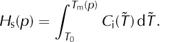
We assume local thermodynamic equilibrium throughout this paper. Thus the absolute temperature and internal energy of the solid/liquid mixture are well defined, the latter up to an additive constant.
The specific enthalpy is defined in some thermodynamics literature (e.g. Reference Moran and ShapiroMoran and Shapiro, 2006) as H = U + p/ρ where U is the specific internal energy and p is the pressure. (Note H and U have SI units J kg-1.) Relative to this literature, in this paper ‘enthalpy’ is synonymous with ‘internal energy’, H = U, because we do not include the work associated with changing the volume, namely the p/ρ term in the specific (per volume) case. That is, we use the name ‘enthalpy’ to match the use of ‘enthalpy’ and ‘enthalpy method’ in other cryospheric applications (e.g. Reference Notz and WorsterNotz and Worster, 2006; Reference Marchenko, Romanovsky, Tipenko, Kane and HinkelMarchenko and others, 2008). Importantly in the glaciermodeling context, our‘enthalpy’ includes neither the (small) kinetic energy density of the mixture nor its (significant) gravitational potential energy density. The latter potential energy reappears in the energy-balance equation as strain- dissipation heating; cf. Eqn (20) below.
For cold ice the temperature, T, is below the pressuremelting point, T m(p). The specific enthalpy, H i, of cold ice is defined as

where C i(T) is the measured heat capacity of ice (e.g. at atmospheric pressure). As noted, this equation defines the ‘internal energy’ (e.g. eqn (4.38) of Reference Greve and BlatterGreve and Blatter, 2009), while other literature refers to it as ‘enthalpy’ (Reference Notz and WorsterNotz and Worster, 2006; Reference Marchenko, Romanovsky, Tipenko, Kane and HinkelMarchenko and others, 2008) or ‘relative enthalpy’ (eqn (4.23) of Reference RichetRichet, 2001). If the reference temperature, T 0, is lower than all modeled ice temperatures then enthalpy values will be positive, though positivity is not important for correctness. The specific enthalpy of liquid water, Hw, is defined as
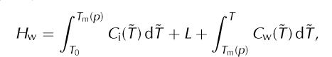
Where C w(T) is the heat capacity of water and L is the latent heat of fusion.
Functions H i(T) and H w(T, p) are defined by Eqns (4) and (5), respectively, so that the enthalpy of liquid water exceeds that of cold ice by at least L. Indeed, if T ≥ T m(p) then H w(T, p) ≥ H i(T m(p)) + L. Supercooled liquid water with T < T m(p) is, however, allowed by Eqn (5).
Experiments suggest that the heat capacity, C i(T), of ice is approximately a linear function of temperature in the range of temperatures commonly found in glaciers and ice sheets (Reference Petrenko and WhitworthPetrenko and Whitworth, 1999, and references therein). For many glacier-modeling purposes it suffices to approximate C i(T) by a constant value independent of temperature. The heat capacity of liquid water, C w(T), is also nearly constant within the relevant temperature range. Thus one may define simpler function H i(T) and H w(T, p), but we will continue with the general forms, given above, until Section 4.
The enthalpy density, ρH (volumetric enthalpy), of the mixture is given by
From Eqns (1), (2), (4), (5) and (6),
Equation (7) describes the specific enthalpy of mixtures, including cold ice, temperate ice and liquid water.
In cold ice we have T < T m(p) and ω = 0. Temperate ice is a mixture which includes a positive amount of solid ice. Neglecting the possibility of supercooled liquid in the mixture, we have T = T m(p) and 0 ≤ ω < 1 in temperate ice. Denote the enthalpy of ω = 0 ice at the pressure-melting temperature by
For mixtures with a positive solid fraction, Eqn (7) now reduces to two cases

We now observe that an inverse function to H i(T) exists under the reasonable assumption that C i(T) is positive. This inverse is denoted T i(H) and it is defined for H < H s(p). Note ∂H i/∂T = C i(T) and thus ∂T/∂H i = C i(T)-1. At this point we can define ice as cold if a small change in enthalpy leads to a change in temperature alone, and temperate if a small change in enthalpy leads to a change in liquid water fraction alone (Reference Aschwanden and BlatterAschwanden and Blatter, 2005, Reference Aschwanden and Blatter2009). The following functions invert Eqn (7) for the range of enthalpy values relevant to glacier and ice-sheet modeling:


Schematic plots of temperature and water content as functions of enthalpy are shown in Figure 2, with points H s and H l(p) = H w(T m(p),p) = H s(p) + L indicated. Equations (10) and (11) will only be applied to cold or temperate ice (mixtures), and therefore H < H l(p) in all cases.
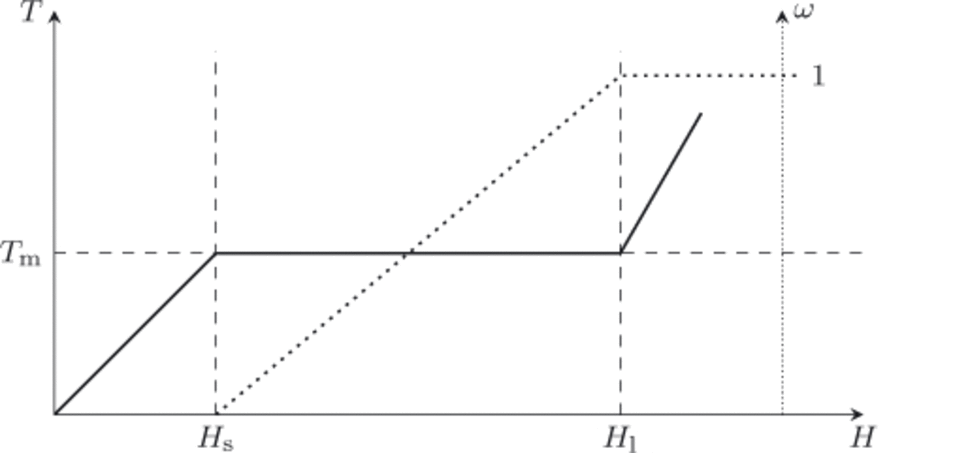
Fig. 2. At fixed pressure, p, the temperature of the ice/liquid water mixture is a function of enthalpy, T = T(H, p) (solid line), as is the liquid water fraction, ω = ω(H, p) (dotted line). Points H s(p) and H l(p) are the enthalpy of pure ice and pure liquid water, respectively, at temperature T m(p).
By Eqns (10) and (11), if the pressure and enthalpy are given then temperature and liquid water fraction are determined. By Eqn (7), if the pressure, temperature and liquid water fraction are given then the enthalpy is determined. It follows that pressure and enthalpy are preferred state variables in a thermomechanically coupled glacier or ice-sheet flow model. From now on, temperature and liquid water fraction are only diagnostically computed, when needed, from this pair of state variables.
3. Continuum Model
3.1. Balance equations
General balance equation
The balance of a quantity, ψ describing particles (fluid) which move with velocity v is given by
where ψv and ϕ are the advective and the non-advective flux density, respectively, and π is a production term (eqn (2.13) of Reference LiuLiu, 2002).
Mass-balance equation
We only allow for the mass to be exchanged between the solid and liquid components of the mixture (i.e. the phases) by melting and freezing. Thus chemical creation of water is not considered. Define M w as the exchange rate between the components, a production term in Eqn (12). Setting ψ = ρi, v = vi, ϕ = 0 and π = -M w in Eqn (12) for the ice component, and similarly for the water component,

Adding Eqns (13) and (14) yields the balance for the mixture
where v is the barycentric velocity (Eqn (3)). However, as noted above, the mixture density, ![]() is approximately constant. Exact constancy of the density would imply that the mixture is actually incompressible,
is approximately constant. Exact constancy of the density would imply that the mixture is actually incompressible,
We have already accepted the constant density approximation, so we adopt Eqn (16), incompressibility, as the mass- conservation equation for the mixture.
Enthalpy-balance and evolution equation
Within the mixture, Σw is the enthalpy exchange rate between the components. The advective and non-advective enthalpy fluxes of the ice component are given by ρ i H iv and qi, respectively, and by p w H wv and qw in the liquid. (Here ‘non-advective’ simply means not proportional to the barycentric velocity, v.) There are also dissipation heating rates, Q w and Q i, for the components, but we will only give an equation for the mixture heating rate, Q = Qw + Q i (Eqn (21), below). The enthalpy balance for the ice component then reads
and similarly for the liquid component,
The smoothness of the modeled enthalpy fields, p i H i and p w H w, is closely related to the empirical form chosen for the non-advective enthalpy fluxes, qi and qw. Differentiability of the enthalpy field for a mixture component follows from the presence of diffusive terms in the corresponding non- advective flux. While we assume that the enthalpy solution is spatially differentiable, its derivatives may be large in magnitude, corresponding to enthalpy ‘jumps’ in practice.
Summing Eqns (17) and (18), and using Eqn (6), gives a balance for the total enthalpy flux:
Setting q = qi + qw, using notation d/dt = ∂/∂t + v ∇ for the material derivative, and recalling incompressibility,
for the mixture. The rate, Q, at which dissipation of strain releases heat into the mixture is
where D is the strain-rate tensor and TD is the deviatoric stress tensor (Reference Greve and BlatterGreve and Blatter, 2009). (Note that momentum- (stress-) balance equations for ice are topics beyond the scope of this paper. In practice, solving the momentum balance in an ice flow computes the velocity, v, pressure, p, strain rates, D, and deviatoric stresses, TD, from ice geometry, softness and boundary stresses. Thus the momentum balance supplies needed fields to the mass and energy balances.)
Equation (20) is our primary statement of conservation of energy for ice. It has the same form as the temperature-only equations already implemented in many cold-ice glacier and ice-sheet models. The complete set of field equations for an enthalpy formulation consists of balance (Eqn (20)), heat source (Eqn (21)), incompressibility (Eqn (16)) and the unstated momentum-balance equation, which may be quite general. Additionally, constitutive equations for the non- advective enthalpy fluxes, qw and qi, and for the viscosity of ice are needed. These are addressed in Section 4.
3.2. On jump equations at boundaries
The mixture mass density, ρ, and mixture enthalpy density, ρH, are well defined in the ice as well as in the air and bedrock, where we assume they have value zero. That is, the air and bedrock are assumed to be water-free in our simplified view, as depicted in Figure 3. The density fields satisfy the stated field equations within the ice, but we now consider their jumps at the upper ice surface and ice base, because they are not continuous at those surfaces. These jump equations then provide boundary conditions for a well- posed conservation-of-energy problem for the ice.

Fig. 3. Jump condition, Eqn (24), is applied to fields ρ and ρH, the mass and enthalpy densities of the ice/liquid water mixture. These fields are defined in air, ice and bedrock. They undergo jumps at the ice upper surface (z = h) and the ice base (z = b). By convention, the normal vector, n, points into the ice domain.
At a general level, suppose that a smooth, non-material, singular surface, σ, separates a region, V, into two subregions V±, (Fig. 9 in Appendix). Let n be the unit normal field on a, pointing from V- to V+. The jump, [[ψ]], of a (scalar) field ψ on σ is defined as
where ψ± are the one-sided limits of ψ in V±.
Now we allow advection of ψ at some velocity, vσ, within and along (tangent to) σ, and we suppose that ψ has area density λa on σ. (For example, the area density, λa, in the mass-balance application in Section 3.3 is the mass per unit area of liquid water in the supraglacial layer.) We also allow production of ψ in the surface, σ, at rate πσ. (In the same example, πσ includes the rainfall mass accumulation rate into the layer.) As shown in the Appendix by a pillbox argument, general balance, Eqn (12), implies a transport- generalized jump condition:
Here wσ is the normal speed of the surface. Equation (23), which is not in the literature to our knowledge, generalizes the better-known Rankine-Hugoniot jump condition (Reference LiuLiu, 2002). Merely stating jump equations, such as Eqn (23), does not ‘close’ the continuum model. Specific descriptions of processes in the thin active layer are still needed, namely supraglacial runoff and subglacial hydrology models in the context of this paper (Section 4.7).
Equation (23) arises as a large-scale approximation of the balance of processes occurring in a thin ‘active’ layer (e.g. of a few meters thickness), confined around the ideal boundary surface, σ, and bounded on either side by threedimensional (3-D) fluids. Thus, Eqn (23) is both a jump condition describing the 3-D field, ψ, and a balance equation for the field, λσ , within the boundary surface. In the latter view the first two jump terms in Eqn (23) are production terms, with the source being the adjacent 3-D field. The density of ψ may also vanish in a portion of the layer (λσ = 0), so that Eqn (23) reverts locally to a pure jump equation for ψ. In glaciological modeling the velocity, vσ, of the thin layer material (e.g. the velocity of liquid water in the supraglacial layer, if present) may be much larger than the 3-D ice mixture velocity, v.
We identify the ice side of boundary surfaces as positive (i.e. as V +) throughout this paper. If ψ is zero on the negative (V-) side of the surface, σ, as it is in the applications in the next two subsections, and if we suppress the ‘+’ superscript for positive-side quantities, Eqn (23) becomes
In the next two subsections we describe both a supraglacial runoff layer and subglacial hydrology layer within this continuum framework. These layers are each governed by a pair of jump equations for the fields ρ and ρH. The analogy between these two layers is deliberate.
3.3. Upper surface
Jump equation for mass
The ice upper surface, σ = {z = h(t, x, y)}, is where the mixture density, ρ, jumps from zero in the air to ![]() in the ice (Fig. 3). Define
in the ice (Fig. 3). Define

so that a unit normal vector for σ pointing from air (V−) into ice (V+) is
The normal surface speed is

Consider the solid mixture component at the upper surface. We make the simplifying assumption that only liquid runoff is mobile in the thin layer at the upper surface, so λσ = 0 and vσ = 0. Ice accumulates perpendicularly at a mass flux rate, ![]() this is snow minus sublimation. Ice also forms at a rate, μ, from freezing of the liquid which is already present in the thin layer, σ. Let ψ = ρ
i, ϕ = 0, v = (mixture velocity), λσ = 0 and
this is snow minus sublimation. Ice also forms at a rate, μ, from freezing of the liquid which is already present in the thin layer, σ. Let ψ = ρ
i, ϕ = 0, v = (mixture velocity), λσ = 0 and ![]() in Eqn (24):
in Eqn (24):
For the liquid component define ![]() where ηh
is the effective meltwater layer thickness. Let vσ = V
h
be the runoff velocity, where vh
= 0 if the surface layer meltwater is not moving. Let
where ηh
is the effective meltwater layer thickness. Let vσ = V
h
be the runoff velocity, where vh
= 0 if the surface layer meltwater is not moving. Let ![]() be the rainfall mass rate; we account for any liquid fraction in snowfall as part of this rate. Choosing ψ = ρw, ϕ = 0 and
be the rainfall mass rate; we account for any liquid fraction in snowfall as part of this rate. Choosing ψ = ρw, ϕ = 0 and ![]() in Eqn (24):
in Eqn (24):
The sum, ![]() is the mixture accumulation function, the mass rate for exchange with the atmosphere. Define the (meltwater-storage-modified) surface mass balance
is the mixture accumulation function, the mass rate for exchange with the atmosphere. Define the (meltwater-storage-modified) surface mass balance
(SI units kgm-2s-1). The ice velocity, v, and the mass balance, Mh , combine to determine the rate of movement, w σ, of the ice surface. Indeed, adding Eqns (28) and (29) and using the definition of Mh (Eqn (30)) gives the surface kinematic equation:
Multiplying through by ρ -1 Nh and using Eqns (26) and (27) gives the equivalent, more familiar form of Eqn (31):

The right-hand side is the ice-thickness-equivalent surface mass-balance rate (SI units ms-1).
Equation (31) describes the jump of ice mixture density, ρ, from air into incompressible ice, generically across a thin layer which may hold surface meltwater (e.g. firn with meltwater or surface ponds on bare ice). Our enthalpy formulation includes the meltwater thickness, ηh, held in this layer, as a state variable. Models which describe a firn layer explicitly could replace Eqn (31) by separate kinematical equations for atmosphere/firn surface and a firn/ice surface below it, in which case η h could describe the meltwater thickness held within the firn.
Jump equation for enthalpy
Snow and rain deliver enthalpy to the ice surface. In general, enthalpy is transported along the surface as well. Enthalpy is also delivered through non-latent atmospheric fluxes (sensible, turbulent and radiative) whose sum we denote qatm. These all affect the jump in the enthalpy density, ρH, as we go from air into ice. Note H is not defined in the air, but ρH has value zero in the air because ρ = 0 there.
For the ice component we assume snowfall occurs at a prescribed temperature, T
snow, which varies in time and space, with corresponding enthalpy, ![]() We denote the enthalpy exchange rate for ice formed by freezing of meltwater as Σ(J m-2 s-1). Again we make the simplifying assumption that λσ
= 0 for the solid component; only liquid is mobile at the surface. Equation (24) with ψ= p
i
H
i, ϕ = (1 - ω)q, ϕ
- = (1- ω)qatm and
We denote the enthalpy exchange rate for ice formed by freezing of meltwater as Σ(J m-2 s-1). Again we make the simplifying assumption that λσ
= 0 for the solid component; only liquid is mobile at the surface. Equation (24) with ψ= p
i
H
i, ϕ = (1 - ω)q, ϕ
- = (1- ω)qatm and ![]() and with other symbols defined as for Eqn (28), gives
and with other symbols defined as for Eqn (28), gives
For the liquid component we make the simplifying assumptions that surface meltwater is at the melting temperature and that variations in atmospheric pressure can be ignored in describing the enthalpy of this surface meltwater. Let T
rain be the temperature of the rainfall, and define ![]() see Eqn (5). Let
see Eqn (5). Let ![]() be the enthalpy of the surface meltwater, a constant. With
be the enthalpy of the surface meltwater, a constant. With  in Eqn (24), we have

Adding the last two equations gives an enthalpy boundary condition for the mixture:

Using Eqns (30) and (31) to simplify Eqn (35), with ![]() factored out of derivatives, the result is a balance for energy fluxes at the ice (mixture) upper surface:
factored out of derivatives, the result is a balance for energy fluxes at the ice (mixture) upper surface:

Equation (36) is the surface energy-balance equation written for use as the boundary condition for the enthalpy- balance equation in an ice-sheet model. It is true at each instant, but its yearly averages may be more easily modeled in practice. Two restricted cases of Eqn (36), which the reader may find more familiar, are addressed next.
First, in areas where there is no surface meltwater(ηh
= 0 so Mh
= a
⊥ by Eqn (30)), and assuming that rainfall occurs at the pressure-melting temperature ![]() and neglecting the typically small conductive heat flux into the ice (q · n = 0), then Eqn (36) is a Dirichlet condition for enthalpy:
and neglecting the typically small conductive heat flux into the ice (q · n = 0), then Eqn (36) is a Dirichlet condition for enthalpy:

This equation says the surface value of the ice mixture enthalpy is the mass-rate-averaged enthalpy delivered by precipitation, plus other (non-latent) atmospheric energy fluxes. If we do not make the q · n = 0 approximation, and instead use a model for conductive heat flux in the ice, such as Eqn (61) (Section 4.1), then Eqn (37) becomes a Robin boundary condition for the enthalpy-balance equation.
A second case, that of periods with no accumulation ![]() gives a rather different equation. We can use Eqn (30) to rewrite Eqn (36) as
gives a rather different equation. We can use Eqn (30) to rewrite Eqn (36) as

That is, the difference between downward-into-the-ice conductive flux, q · n, and the non-latent atmospheric energy fluxes, qatm · n, is balanced by meltwater storage and transport.
If we use a model for conductive heat flux in the ice, such as Eqn (61), then both Eqn (38) and the general form (Eqn (36)) are Robin boundary conditions for the enthalpy- balance equation, but we must generally have a model for storage and transport of meltwater (i.e. a dynamical model for η h = η h (t, x, y)) to use them this way. For much of the year there is no liquid water at the surface of a glacier (ηh = 0), in which case Eqn (38) merely says there is a balance of non-latent fluxes (q · n = qatm · n), a Neumann condition for the enthalpy-balance equation if we have Eqn (61). During periods of intense melt, or in areas with runoff ponding, for example, we must use Eqn (38) or the general form (Eqn (36)). However, if the accumulation is regarded as occurring steadily over longer periods (e.g. months), and if there is minimal meltwater in the surface layer, then Eqn (37) is likely to be a better model. The general form (Eqn (36)) is presumably best if the model has sufficient complexity.
Our analysis does not include the energy released by viscous strain-dissipation heating by flow of the liquid runoff itself. Also we have not included the energy released by firn compaction. Improved models of these processes could add production terms to either or both of the component balances, Eqns (33) and (34), with resulting modifications to Eqn (36).
3.4. Ice base
Jump equation for mass
The analysis of the basal layer is similar to the meltwater layer at the upper surface. At the base, pressure, frictional heating and geothermal flux play new roles. However, at the ice base we make the simplifying assumption that there is no mass accumulation from sources outside the ice sheet or its subglacial layer. Thus all liquid in this layer originates from melting of the ice above, or from transport in the layer. For simplicity, we suppose that only pressure-melting- temperature liquid water may move in the layer.
In Eqn (40), below, we parameterize the subglacial aquifer by an effective layer thickness, η b , and an effective subglacial liquid velocity, vb. When the ice basal temperature is below the pressure-melting point then we assume η b = 0 and v b = 0. We assume this aquifer has a liquid pressure, Pb , called the ‘pore-water pressure’, as if the liquid is in the pore spaces of a permeable till. This pressure does not need to be defined where η b = 0 All fields, η b , v b ,P b may vary in time and space.
Our general enthalpy formulation does not include a specific hydrological model ‘closure’. Such a closure would relate the flux, η b v b , to the pressure, pb , as in Darcy flow, for example (cf. Reference ClarkeClarke, 2005). Such a closure is needed to build an effective glacier model. See Section 5.1 for a simple example closure.
Assuming the base, σ = {z = b(t, x, y)}, is a differentiable surface, define ![]() The surface (unit) normal vector, n, points from bedrock (V-) into ice (V+). The normal surface speed of the ice base is
The surface (unit) normal vector, n, points from bedrock (V-) into ice (V+). The normal surface speed of the ice base is ![]()
For the mass balance of the ice component, let ψ = ρi, ϕ = 0, λσ = 0 and πo = μ in Eqn (24), where μ is the mass exchange rate between the liquid and the solid phase:
Similarly for the liquid component, let ψ = ρ
w, ϕ = 0, ![]() in Eqn (24), where ηb
is the basal water layer thickness and v
b
is the basal water velocity:
in Eqn (24), where ηb
is the basal water layer thickness and v
b
is the basal water velocity:

Define the ice base mass-balance rate

(SI units kgm-2s-1). This quantity is analogous to the meltwater-storage-modified surface mass balance, Mh , defined in Eqn (30), but at the ice base there is no accumulation from external supply. The negative of Mb is called the basal melt rate. This is the rate at which hydrological storage and transport mechanisms deliver liquid water to the base of the ice at a subglacial location. Equation (41) occurs in the literature (e.g. Eqn (4) of Reference Johnson and FastookJohnson and Fastook, 2002).
Adding Eqns (39) and (40) gives a basal kinematic equation, ρ(v · n - w σ) = Mb . Using the expressions for n and w σ, and multiplying through by ρ-1 Nb gives the more familiar form:

Jump equation for enthalpy
The ice mixture enthalpy density, ρH, jumps from zero in the bedrock to its value in the ice. That is, for simplicity we do not track the latent energy content of water deep within the bedrock (aquifers or permafrost below a thin, active subglacial layer).
Heat is supplied to the subglacial layer by the geothermal (lithospheric) flux, qlith. The stress applied by the lithosphere to the base of the ice is f = – T · n, where T is the Cauchy stress tensor, with shear component τ b = f – (f · n)n (‘shear traction’, Reference LiuLiu, 2002). Therefore the frictional heating arising from sliding is Fb = τ b · v, a positive surface flux, if v is the velocity of the ice.
Let Σ be the enthalpy density exchange rate between ice and liquid components in the subglacial layer. For the energy balance of the ice component, substitution of ψ = ρ i H i, ϕ+ = (1 - ω)q, ϕ- = (1 – ω)qlith, λσ = Σ + (1 – ω)Fb in Eqn (24) yields
For the water component we use analogous choices to those in Eqn (40): substitute ![]()
![]() in Eqn (24).This gives
in Eqn (24).This gives
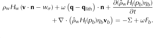
Equations (43) and (44) have terms (e.g. ‘(1 - ω)q’, ‘(1 - ω)Fb ’, ‘ωq’ and ‘ωFb ’) for heating in each component separately. This is only a representative distribution between the phases, because Eqn (47), for the mixture, is used in modeling, and not Eqns (43) or (44) directly. We have included such a distribution of heat to the components so as to clarify the derivation of Eqn (47), below. Similar to Eqn (41), we now define

This is the rate at which hydrological storage and transport mechanisms deliver latent heat to the base of the ice at a subglacial location. (For example, if the basal water layer grows in thickness but the water is not flowing laterally, that is if ∂/∂t > 0 in Eqn (45) but the divergence portion is zero because v b is zero, then Qb is negative because enthalpy is being removed from the base of the glacier for delivery to the subglacial liquid.) Adding component Eqns (43) and (44), and applying the definition of Mh (Eqn (45)) gives
Recalling the basal kinematic equation (42) in its simplified form, ρ(v · n – wσ ) = Mb , we may rewrite Eqn (46) as
The ‘H’ on the left-hand side of Eqn (47) is the value of the enthalpy of the ice mixture at its base, which is generally different from the enthalpy of the subglacial liquid water (= H l(pb ), as in Eqn (45)).
Liquid water that is transported in the subglacial aquifer can undergo phase change merely because of changes in the pressure-melting temperature in this water (section 4.1.1 of Reference ClarkeClarke, 2005). This situation is addressed by Eqn (47) through the role of pb in Qb (Eqn (45)). Conversely, the pressure in the subglacial aquifer can be altered because of energy fluxes into, and within, the subglacial aquifer. In other words, Eqn (47) can be rewritten as a partial differential equation for the subglacial liquid water pressure. Indeed, from Eqns (41) and (45), with dpb /dt = ∂pb /∂t + v b · ∇ pb and γ = ∂H 1(pb )/∂pb , we can eliminate Qb from Eqn (47) to get
Equation (48) describes how pore-water pressure changes, dpb /dt, are related to energy fluxes into the subglacial layer. It does not, however, fully determine such changes without a closure, a connection between η b and Pb .
We define a point in the basal surface, σ = {z = p}, to be ‘cold’ if H < H s(p) and η b = 0, and ‘temperate’ otherwise. If all points of a portion of σ are cold then Eqn (41) implies Mb = 0 and Eqn (45) implies Qb = 0, so Eqn (47) then says
Thus, the heat entering the base of the ice mixture combines geothermal and frictional heating. In fact, Eqn (49) is the standard heat flux boundary condition for the base of cold ice, including ‘hard bed’ sliding (Reference ClarkeClarke, 2005). It is a Neumann boundary condition if we adopt a conductive flux model for ice, such as Eqn (61) (Section 4.1).
The subglacial aquifer is subject to the obvious positivethickness inequality, ηb ≥ 0. If the ice base is temperate then the η b = 0 situation is unstable, however. In fact Eqn (47) implies that any heat imbalance, however slight, can immediately generate a nonzero melt rate if the basal temperature is at the pressure-melting value. By the definition of ‘cold’ base just given, the temperate base case is where either H ≥ Hs(p) or η b ≥ 0. This case simplifies to’H ≥ Hs(p) and η b ≥ 0 if the subglacial liquid is assumed to be at the pressure-melting temperature (not supercooled). That is, if η b ≥ 0 then heat will move so that the base of the ice mixture has H ≥ Hs(p).
The temperate base case permits the interpretation of Eqn (47) as a basal melt rate calculation. The basal melt rate itself (-Mb ) can be either positive (melting) or negative (subglacial liquid freezes onto the base of the ice). From Eqn (48) we can also write the basal melt rate in terms of heat fluxes and changes in the pore-water pressure (dp b /dt):

Similar to the supraglacial runoff layer, energy production due to strain-dissipation heating within the subglacial aquifer is not included (Section 3.3). Another possibility, also not addressed in this paper, is that liquid water could enter the thin subglacial layer from aquifers deeper in the bedrock (cf. eqn (9.123) of Reference Greve and BlatterGreve and Blatter, 2009). The possibility that the subglacial aquifer could be connected directly to the supraglacial runoff layer by moulin drainage is not modeled either. Finally, we have not attempted to model sediment transport.
4. Simplified Theory Including Constitutive Relations
The mathematical model derived in the previous sections is general enough to apply to a wide range of numerical glacier and ice-sheet models. It is neither limited to a particular stress balance nor a particular numerical scheme. In this section, however, we propose constitutive equations, simplified parameterizations and shallow approximations which make an enthalpy formulation better suited to current modeling practice.
4.1. Constitutive equations
Enthalpy flux
The non-advective heat flux in cold ice, namely that flux which is not advective at the mixture velocity, is given by Fourier’s law (e.g. Reference PatersonPaterson, 1994),
where ki (T) is the thermal conductivity of cold ice. Combining Eqns (10) and (51) allows us to write the heat flux in terms of the enthalpy gradient in cold ice,
The last expression in Eqn (52) is written in terms of enthalpy, a key step in an enthalpy-gradient method (Reference PhamPham, 1995; Reference Aschwanden and BlatterAschwanden and Blatter, 2009). In fact, let
thus
Fourier’s law for cold ice now has the enthalpy form
The non-advective heat flux in temperate ice is the sum of sensible and latent heat fluxes (Reference GreveGreve, 1997a),
The sensible heat flux, qs, in temperate ice is conductive, arising from variations in the pressure-melting temperature. The mixture conductivity, written in terms of enthalpy and pressure, is
where kw is the thermal conductivity of liquid water (cf. Eqn (3) of Reference Notz and WorsterNotz and Worster, 2006). By Fourier’s law the sensible heat flux has enthalpy form
The latent heat flux, ql, in temperate ice is proportional to the mass flux of liquid water, j, relative to the barycenter:
Flux j is sometimes called the ‘diffusive water flux’ (Reference Greve and BlatterGreve and Blatter, 2009), but we prefer to identify it as ‘non- advective’ until a diffusive constitutive relation is specified. A constitutive equation for j is required for implementability; however, Reference HutterHutter (1982) suggested a general formulation, involving liquid water fraction, its spatial gradient, deformation and gravity. Two specific realizations have been proposed, a Fick-type diffusion (Reference HutterHutter, 1982) and a Darcy-type flow (Reference FowlerFowler, 1984). However, laboratory experiments and field observations to identify the constitutive relation are scarce. A drop in liquid water fraction was observed close to the bed at Falljokull in Iceland (Reference Murray, Stuart, Fry, Gamble and CrabtreeMurray and others, 2000) and on the upper plateau of the Vallee Blanche in the massif du Mont- Blanc (Reference Vallon, Petit and FabreVallon and others, 1976), and these observations suggest a gravity-driven flow regime may exist at higher water fractions. They support the flexible Reference HutterHutter (1982) form.
But we admit that even the functional form of ql is poorly constrained at the present state of experimental knowledge. Greve (1997a) writes the simplest possible form by setting the latent heat flux, ql, to zero in temperate ice. Our assumption that the enthalpy field has finite spatial derivatives within the ice explains our regularizing choice instead, namely
where k 0 and K 0 = L -1 k 0 are small positive constants. This form may be justified by a Fick-type diffusion (Reference HutterHutter, 1982), or even by observing that numerical schemes approximating the hyperbolic equation arising from the choice ql = 0 will automatically generate some numerical diffusion (Reference GreveGreve, 1997a). Mathematically, this regularization makes the enthalpy field, Eqn (67), coercive, which explains why the same regularization was used by Reference Calvo, Durany and VazquezCalvo and others (1999).
From Eqns (55), (56), (58) and (60), we have now expressed the heat flux in terms of enthalpy and pressure,

Ice flow
Laboratory experiments suggest that glacier ice behaves like a power-law fluid (e.g. Reference SteinemannSteinemann, 1954; Reference GlenGlen, 1955), so its effective viscosity, η, is a function of an effective stress, τe, a rate factor (softness), A, and a power, n,
The small constant, ∈ (units of stress), regularizes the flow law at low effective stress, avoiding the problem of infinite viscosity at zero deviatoric stress (Reference HutterHutter, 1983).
In terrestrial glacier applications, ice behaves similarly to metals and alloys with a homologous temperature near 1. In cold ice it is common to express the rate factor with the Arrhenius law,
where A 0, Q a, V and R are constant (or have additional temperature dependence; Reference PatersonPaterson, 1994). For temperate ice, however, little is known about the effect of liquid water on viscosity. In experimental studies, Reference DuvalDuval (1977) and Reference Lliboutry and DuvalLliboutry and Duval (1985) derived the following function for the rate factor in temperate ice, A t(ω, p), valid for water fractions <0.01 (or 1%),
as given by Reference Greve and BlatterGreve and Blatter (2009). In any case we may write the rate factor as a function of the enthalpy variable and pressure using the functions defined in Eqns (63) and (64):

Subglacial water pressure
A commonly adopted simplified view neglects pressure variation in time when determining the subglacial liquid enthalpy (i.e. dp b /dt = 0). It also assumes that the basal pressure, p, of the ice mixture is at the same value. In fact, for this paragraph let p 0 be the common pressure both of the subglacial liquid and of the basal ice, and assume it is constant in time and space. Assuming the basal ice is temperate because subglacial liquid is present, the basal ice mixture enthalpy is then H = H s(p 0) + ωL and the subglacial liquid enthalpy is H l(p 0) = H s(p 0) + L. By constancy of the pressure, Eqns (41) and (45) imply Q b = H l(p 0)Mb , and Eqn (47) says that

Equation (66) appears in many places in the literature, though the constant-pressure assumption is rarely made explicit. For example, it matches eqn (5.40) of Reference Greve and BlatterGreve and Blatter (2009) in the case ω = 0 (noting a substitution ![]() and a change in sign of the normal vector, n). Similar notational changes give Eqn (5) of Reference ClarkeClarke (2005). However, we believe that Eqn (47) (and its equivalent forms, Eqns (48) and (50)) is more fundamental, or at least more energy-conserving, than Eqn (66), as it applies even in cases with variable subglacia aquifer pressure, pb
and a change in sign of the normal vector, n). Similar notational changes give Eqn (5) of Reference ClarkeClarke (2005). However, we believe that Eqn (47) (and its equivalent forms, Eqns (48) and (50)) is more fundamental, or at least more energy-conserving, than Eqn (66), as it applies even in cases with variable subglacia aquifer pressure, pb
4.2. Field equation for enthalpy
Inserting Eqn (61) into Eqn (20) yields the enthalpy field equation of the ice mixture, the conduction term of which depends on whether the mixture is cold (H < H s(p)) or temperate (H ≥ H s(p)):

4.3. Hydrostatic simplifications
The pressure, p, of the ice mixture appears in all relationships between enthalpy, temperature and liquid water fraction (Section 2). Simplified forms apply in flow models which make the hydrostatic pressure approximation (Reference Greve and BlatterGreve and Blatter, 2009)
Recall also the Clausius-Clapeyron relation

where β is constant (Reference LliboutryLliboutry, 1971; Reference HarrisonHarrison, 1972). In this subsection we derive consequences of Eqns (68) and (69).
Within temperate ice the sensible heat flux term in enthalpy field Eqn (67) is transformed:

Recall that k = k(H, p) varies within temperate ice while K0 is constant (Section 4.1). For small values of the liquid water fraction (cf. Section 4.6), a further simplification identifies the mixture thermal conductivity with the constant thermal conductivity of ice,
(cf. Eqn (57)). In temperate ice the enthalpy flux divergence term then combines an essentially geometric additive factor, proportional to the Laplacian, ∇2 h, and thus related to the curvature of the ice surface, with a small (true) diffusivity for K 0 > 0, as follows:
Defining Γ = −βρgk i∇2 h, enthalpy field Eqn (67), again with cases for cold and temperate ice, simplifies to:

The geometric factor, Γ, can be understood physically as a differential heating or cooling rate of a column of temperate ice by its neighboring columns with differing surface heights. It represents a small contribution to the overall heating rate, however, especially relative to dissipation heating, Q (Reference Aschwanden and BlatterAschwanden and Blatter, 2005). In terms of typical values, with a strain rate 10−3 a−1 and a deviatoric stress 105 Pa (Reference PatersonPaterson, 1994) we have Q ≈ 3 × 10⁻⁶ Jm−3 s−1. Furthermore, if the ice upper surface changes slope by 0.001 in horizontal distance 1 km then |∇2h| ≈ 10-6 m-1. Using the constants from Table 1, below, we have |Γ| ≈ 2 × 10⁻⁹ J m-3 s-1, three orders of magnitude smaller than Q. Of course, ∇2 h does not really have a ‘typical value’ because, even in the simplest models, it has unbounded magnitude at ice-sheet divides (section 5.6 of Reference Greve and BlatterGreve and Blatter, 2009) and margins (Reference Bueler, Lingle, Kallen-Brown, Covey and BowmanBueler and others, 2005). Examination of a typical digital elevation model for Greenland suggests |∇2 h| < 10-6m-1 for >95% of the area, however. For these reasons we implement the simplest model in Section 5.1, i.e. Γ = 0 in Eqn (73).
Table 1. Parameters used in Section 5.2. Constants c i and k i were used for the runs ENTH and TEMP, while Eqns (75) and (79) were used for run VARCK

Regardless of the magnitude of Γ, Eqn (73) is parabolic in the mathematical sense. That is, its highest-order spatial derivative term is uniformly elliptic (Reference Ockendon, Howison, Lacey and MovchanOckendon and others, 2003). We expect that min {K i(H), K 0} = K 0, and we assume a positive minimum value of the conductivity coefficient in Eqn (73) (i.e. ‘coercivity’; Reference Calvo, Durany and VazquezCalvo and others, 1999). It follows that the initial/boundary-value problem formed by Eqn (73), along with boundary conditions which are of mixed Dirichlet and Neumann type (Section 4.7), is well posed (Reference Ockendon, Howison, Lacey and MovchanOckendon and others, 2003). Equation (73) is strongly advection- dominated, however, and numerical schemes should be constructed accordingly.
4.4. Shallow enthalpy equation
In addition to hydrostatic approximation, some ice-sheet models use the small aspect ratio of ice sheets to simplify their model equations. Heat conduction can be shown to be negligible in horizontal directions in such models (Reference Greve and BlatterGreve and Blatter, 2009). With this simplification, and taking Γ = 0 for the reasons above, Eqn (73) becomes

where the first case is used when H < H s(p) and the second case when H ≥ H s(p). Equation (74) is used in the PISM implementation in Section 5. One may consider the further simplification that K i(H) = K is constant for cold ice. Greenland simulations which include this further simplification are compared in Section 5.2 to simulations without it. In either case, however, the vertical diffusivity, K = K(H), in the enthalpy-balance equation remains enthalpy-dependent because of its jump from K 0 to K i at H = H s(p). Therefore we use a standard semi-implicit scheme for the vertical conduction problem (e.g. eqn (5.182) of Reference Greve and BlatterGreve and Blatter, 2009).
4.5. On the constant heat capacity simplification
The heat capacity, Ci(T), of ice varies by ~10% in the temperature range between -30oC and 0°C (Reference Greve and BlatterGreve and Blatter, 2009). Also C i(T) is approximately linear in this range,
where T is in Kelvin (eqn (4.39) of Reference Greve and BlatterGreve and Blatter, 2009). Note that H i(T), the integral of C i(T) with respect to T, is therefore quadratic in temperature. Itfollows that conversion between temperature and enthalpy using Eqns (9) and (10) requires solving quadratic equations.
As a simplest model of heat capacity, we might choose a constant heat capacity, c i = 2009 J kg-1 K-1 (e.g. Reference PaynePayne and others, 2000), corresponding to a reference temperature of T r = -16.33°C in Eqn (75). This linearizes the equation for H i(T) so that H s(p) = c i(T m(p) – T 0) and

Though this formulation is simplified, it is used by Reference LliboutryLliboutry (1976), Reference Calvo, Durany and VazquezCalvo and others (1999) and Reference KatzKatz (2008), who all employ constant specific heat capacity.
The consequences of using Eqn (76) for Greenland simulations, versus the more general C = Ci(T) case, are small but quantifiable, as described in Section 5.2. However, the performance cost of using the general C = Ci(T) case is also small. It is not clear when the general case is needed in ice-sheet simulations.
4.6. A minimal drainage model
Observations do not support a particular upper bound on liquid water fraction, ω, but reported values above 3% are rare (Reference Pettersson, Jansson and BlatterPettersson and others, 2004, and references therein). At sufficiently high ω values, drainage occurs simply because liquid water is denser than ice. Available parameterizations, especially the absence of flow laws for ice with ω > 1% (Reference Lliboutry and DuvalLliboutry and Duval, 1985), also suggest keeping ω in the experimentally tested range. Also, though a parameterized drainage mechanism is not required to implement an enthalpy formulation, we observe in model runs that, without drainage, large strain-heating rates raise liquid water fraction to unreasonable levels.
For such reasons Greve (1997b) introduced a ‘drainage function’, and we adapt it to the enthalpy context. Let D(ω)Δt be the dimensionless mass fraction removed in time Δt by drainage of liquid water to the ice base. Note that D(ω) is a rate, and the time-step and drainage rate must satisfy D(ω)Δt ≤ 1 so that no more than the whole mass is drained in one time-step. The mass removed in the time-step is ![]() Though Greve (1997b) proposes D(ω) = + ∞ for ω ≥ 0.01, choosing D(ω) to be finite increases the regularity of the enthalpy solution. Figure 4 shows an example drainage function which is zero for ω < 0.01 and which is finite. At ω = 0.02 the rate of drainage is 0.005 a-1 while above ω = 0.03 the drainage rate of 0.05 a-1 is sufficient to move the whole mass, if it should melt, to the base in 20 years. Though application of this function allows ice with ω > 0.01, we observe in modeling use that such values are rare; see Section 5.2. We cap the ice softness computed from the flow law, Eqn (64), at its ω = 0.01 level to stay in the experimentally observed range of ice softness values.
Though Greve (1997b) proposes D(ω) = + ∞ for ω ≥ 0.01, choosing D(ω) to be finite increases the regularity of the enthalpy solution. Figure 4 shows an example drainage function which is zero for ω < 0.01 and which is finite. At ω = 0.02 the rate of drainage is 0.005 a-1 while above ω = 0.03 the drainage rate of 0.05 a-1 is sufficient to move the whole mass, if it should melt, to the base in 20 years. Though application of this function allows ice with ω > 0.01, we observe in modeling use that such values are rare; see Section 5.2. We cap the ice softness computed from the flow law, Eqn (64), at its ω = 0.01 level to stay in the experimentally observed range of ice softness values.

Fig. 4. An example finite drainage function.
Strictly speaking, inclusion of such a drainage function implies that the ice mixture is no longer incompressible. Indeed, drained water is transported to the base by an un-modeled mechanism. In practice, we must modify the computation of basal melt rate, and, in a shallow model, also the computation of the vertical velocity. Specifically, drained water adds the basal melt rate, -Mb , to give a new value as follows:

The vertical velocity is then computed using incompressibility and Eqn (77):

We also modify Eqn (50), or its simplified version, Eqn (66).
In an ice dynamics model, the ice mixture velocity enters into a mass-continuity equation. Therefore the basal melt rate, including the drainage contribution, affects the rate of change of ice-sheet thickness. The basal melt rate also affects the vertical velocity (Eqn (78)). These effects may or may not be included in a given ice dynamics model, but sliding flow can still be strongly influenced by the basal melt rate. The basal melt rate is the leading control on water pressure in the subglacial aquifer and thus on the modeled basal strength (e.g. till yield stress; cf. Reference Bueler and BrownBueler and Brown, 2009). This coupling may be the most important consequence of inclusion of drainage in an ice dynamics model.
A back-of-the-envelope calculation also suggests the importance of drainage to an ice dynamics model. Consider the Jakobshavn drainage basin on the Greenland ice sheet, with yearly average surface mass balance of ~0.4ma-1 ice equivalent (Reference EttemaEttema and others, 2009), area ~10n m2 and average surface elevation ~2000m. If the surface of this region were to drop uniformly by 1m in a year, then the gravitational potential energy released is sufficient to fully melt 2 km3 of ice. This energy will be dissipated by strain heating at locations where strain rates and stresses, and basal frictional heating, are highest. It follows that a model with 3-D gridcells of typical size 1 km3 (e.g. 10 km × 10 km × 10 m) should sometimes generate liquid water fractions far above 0.01 if drainage is not included. Under abrupt, major changes in basal resistance or calving-front back pressure, with corresponding changes to strain rates and thus strain heating, it is possible that some gridcells of 1 km3 size are completely melted if time-steps on the order of 1 year are taken. Model time-steps should be shortened so that generated liquid water is drained over many time-steps.
4.7. Simplified boundary conditions
In order for ice-sheet and glacier models to get the greatest benefit from an enthalpy formulation, the surface process components should report the meltwater-storage-modified net accumulation, Mh
(Eqn (30)), and also separated snowfall rate, ![]() rainfall rate,
rainfall rate, ![]() , and 2 m air temperature to the ice thermodynamics ‘core’. These quantities are needed to fully apply the upper surface conditions in Section 3.3. The surface kinematic equation, Eqn (31), is used in determining the surface elevation changes, though in shallow models one may rewrite the kinematic equation to give a map-plane mass-continuity equation (e.g. Reference Bueler and BrownBueler and Brown, 2009), and Mh
appears in this equation. In either case, Mh
is needed to determine the motion of the upper surface of the ice.
, and 2 m air temperature to the ice thermodynamics ‘core’. These quantities are needed to fully apply the upper surface conditions in Section 3.3. The surface kinematic equation, Eqn (31), is used in determining the surface elevation changes, though in shallow models one may rewrite the kinematic equation to give a map-plane mass-continuity equation (e.g. Reference Bueler and BrownBueler and Brown, 2009), and Mh
appears in this equation. In either case, Mh
is needed to determine the motion of the upper surface of the ice.
Generally Eqn (36) for the upper surface is a Robin boundary condition (Reference Ockendon, Howison, Lacey and MovchanOckendon and others, 2003) for the enthalpy balance, Eqn (67). Equation (36) involves both the surface value of the ice enthalpy and its normal derivative. In addition to the mass flux rates already needed for the mass-conservation boundary condition, surface process components need some model to compute qatm, the nonlatent heat flux from the atmosphere, in order to fully exploit the enthalpy formulation. (Clearly this is beyond the scope of this paper.) Surface type is also important in applying Eqn (36); is there a positive thickness layer of firn throughout the year or is the surface bare ice in the melt season?
Simpler models can use the temperature at the surface more directly. As noted, Eqn (36) is also often reduced to the Dirichlet boundary condition, Eqn (37), by neglecting the conductive heat flux into the ice. In Eqn (37) the temperatures are for the precipitation itself, but the PISM Greenland example, below, is yet simpler because such temperature data are lacking. In glaciological applications, it is common (e.g. Reference OhmuraOhmura, 2001) to use the 2 m air temperature, T 2m, as a surrogate for ice surface temperature. In this example the Dirichlet boundary condition is H = H(T 2m,0,p atm), in terms of the function H(T, ω, p) defined by Eqn (76), where p atm is the atmospheric pressure.
Figure 5 describes the application of the basal boundary condition and the associated computation of the basal melt rate. Note that in the temperate base case, where ηbmay be zero or positive and where H ≥ H s(p), either Eqn (50) or Eqn (66) allows us to compute a nonzero basal melt rate, –M b . In doing so, however, we are left needing independent information on the boundary condition to the enthalpy field, Eqn (67), itself. Because that equation is parabolic, a Neumann boundary condition may be used but the ‘no boundary condition’ applicable to pure advection problems is not mathematically acceptable. Because the basal melt rate calculation will balance the energy at the base, a reasonable model is to apply an insulating Neumann boundary condition, K 0∇ H · n = 0, in the case of a positivethickness layer of temperate ice, and apply a Dirichlet boundary condition, H = Hs(p), if the basal temperate ice has zero thickness. In the discretized implementation, whether there is a positive-thickness layer is determined using a criterion such as H(+Δz) > H s(p(+Δz)).
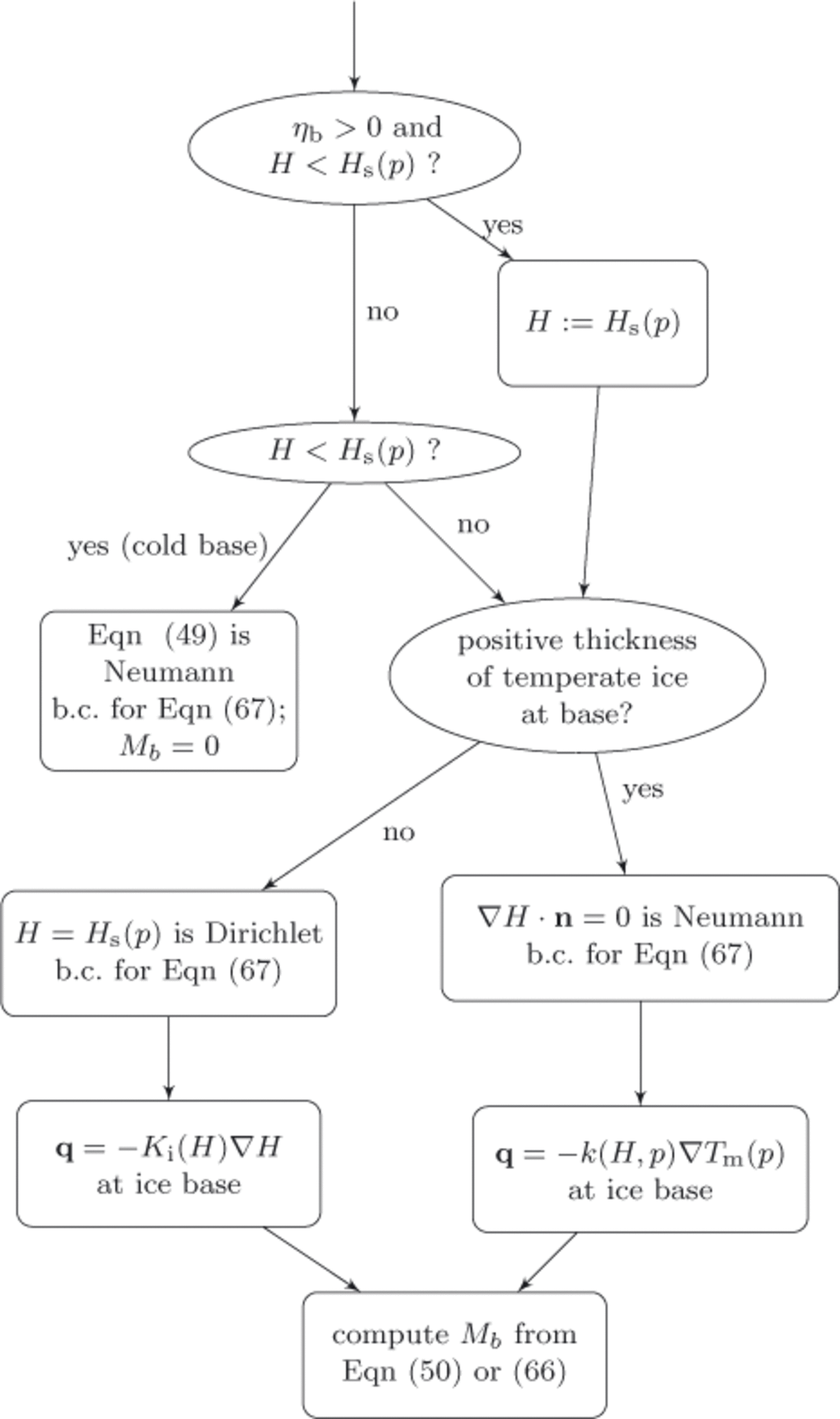
Fig. 5. Decision chart for each basal location. Determines basal boundary condition for enthalpy field equation (67), identifies the expression for upward heat flux at the ice base and computes basal p>melt rate, −Mb. The basal value of the ice mixture enthalpy is ‘H’; b.c.: boundary conditions.
4.8. On bedrock thermal layers
Ice-sheet energy conservation models may include a thin layer of the Earth’s lithosphere (bedrock), of at most a few kilometers. The heat flux, qlith = –k
lith∇T, which enters into the subglacial layer energy balance, Eqn (47), varies in response to changes in the insulating thickness of overlain ice, and this explains why the temperature in the bedrock is modeled. An observed geothermal flux field, ![]() is generally part of the model data, and if a bedrock thermal layer is present then it forms the Neumann lower boundary condition for that layer.
is generally part of the model data, and if a bedrock thermal layer is present then it forms the Neumann lower boundary condition for that layer.
Though the numerical scheme for a bedrock thermal model could be implicitly coupled with the ice above, a simpler view with adequate numerical accuracy comes from splitting the conservation-of-energy time-step into a bedrock time-step followed by an ice time-step. In that case the temperature of the top of the lithosphere is held fixed, as a Dirichlet condition, for the duration of the bedrock time- step. The flux, qlith, at the top of the bedrock is computed as an output of the bedrock thermal layer model. The (ice) enthalpy formulation sees this computed flux as a part of its basal boundary condition (Section 4.7) during its time-step.
5. Results
5.1. Implementation in PISM
The simplified enthalpy formulation of the last section was implemented in the open-source Parallel Ice Sheet Model (PISM). Because other aspects of PISM are well documented (Reference Bueler, Brown and LingleBueler and others, 2007; Reference Bueler and BrownBueler and Brown, 2009; Reference WinkelmannWinkelmann and others, 2011; http://www.pism-docs.org), we only outline enthalpy-related aspects here. We note significant implementation changes that update or replace previous work.
Conservation-of-energy Eqn (74) replaces the temperature- based equation used previously (e.g. Eqn (7) of Reference Bueler and BrownBueler and Brown, 2009). At the upper ice surface, the Dirichlet condition for enthalpy is determined from an assumed upper surface temperature. At the ice base, the decision chart in Figure 5 is applied to determine the boundary condition for enthalpy. Equations (66) and (77) are used to compute basal melt, so the drainage and basal melt model in this paper replaces that of Reference Bueler and BrownBueler and Brown (2009). The finite-difference scheme used here for conservation of energy is essentially the same as that described by Reference Bueler, Brown and LingleBueler and others (2007), but with temperature replaced by enthalpy. The combined advection/conduction time-stepping problem in the vertical is solved implicitly, avoiding time- step restrictions based on vertical ice velocity (cf. Reference Bueler, Brown and LingleBueler and others, 2007). For the reasons given in Section 4.8, the bedrock thermal layer model now couples to the ice enthalpy problem in an explicit time-stepping manner. The lateral diffusion scheme for basal water of Reference Bueler and BrownBueler and Brown (2009) is not used; instead, the basal hydrology model is simplified. Namely, any generated basal melt is stored in place, it is limited to a maximum of 2 m effective thickness, refreeze is allowed and stored water is removed at a fixed rate of 1 mma-1 in the absence of active melting or refreeze.
5.2. Application to Greenland
Our goals here in applying the enthalpy formulation to Greenland are limited. We show results from the enthalpy formulation and a cold-ice method, and we compare the major thermodynamic fields qualitatively. A more comprehensive sensitivity analysis addressing non-steady conditions, sliding, spin-up choices, etc., is beyond our current scope.
To make our results easier to compare with the literature, we use the European Ice-Sheet Modelling Initiative (EIS- MINT) set-up for Greenland (Reference HuybrechtsHuybrechts, 1998). It provides bedrock and surface elevation, parameterizations for surface temperatures and precipitation, and degree-day factors. Our restriction to the non-sliding shallow-ice approximation is in keeping with EISMINT model expectations (Reference HutterHutter, 1983).Footnote * . Because there is no sliding, F b = 0 in Eqn (66). Three experiments † were carried out, two using an enthalpy formulation (ENTH and VARCK) and one using a temperature- based method (TEMP). Parameters common to all runs are listed in Table 1. Run ENTH uses constant values for specific heat capacity and heat conductivity, so Eqn (76) applies. By contrast, VARCK uses the enthalpy formulation based upon the functions of temperature given by Greve and Blatter (2009), namely Eqn (75) for C i(T) and
For both ENTH and VARCK the rate factor in temperate ice is calculated according to Eqn (64) and the temperate ice diffusivity in Eqn (74) was chosen to be K 0 = 1.045 × 10⁻⁴ kgm-1 s-1, which is an order of magnitude smaller than the value, K i = k i/c i, for cold ice. As explained in Section 4.1, this choice may be regarded as a regularization of the enthalpy equation, but the results of Reference Aschwanden and BlatterAschwanden and Blatter (2009) suggest this value is already in the range where the CTS is stable with respect to further reductions of K 0.
All three runs start from the observed geometry, and the same heuristic estimate of temperature at depth, and occur on a 20 km horizontal grid run for 230 ka. At this model time, the grid is refined to 10 km, all quantities are bilinearly interpolated to the finer grid and the run continues for an additional 20 ka. We use an unequally spaced vertical grid, with spacing from 5.08 m at the ice base to 34.9 m at the top of the computational domain, and a 2000 m thick bedrock thermal layer with 40 m spacing.
The majority of the Greenland ice sheet has a Canadian thermal structure, if there is any temperate ice in the ice column at all, and all three runs agree on this basic structure.*Both methods predict a majority of the basal area to be cold, with run TEMP giving significantly greater temperate basal area and temperate volume fraction than the other runs (Table 2). The spatial distribution of fields from experiment VARCK is in close agreement with ENTH and is not shown in the following. Figure 6 shows that simulated basal temperatures are similar between runs ENTH and TEMP.
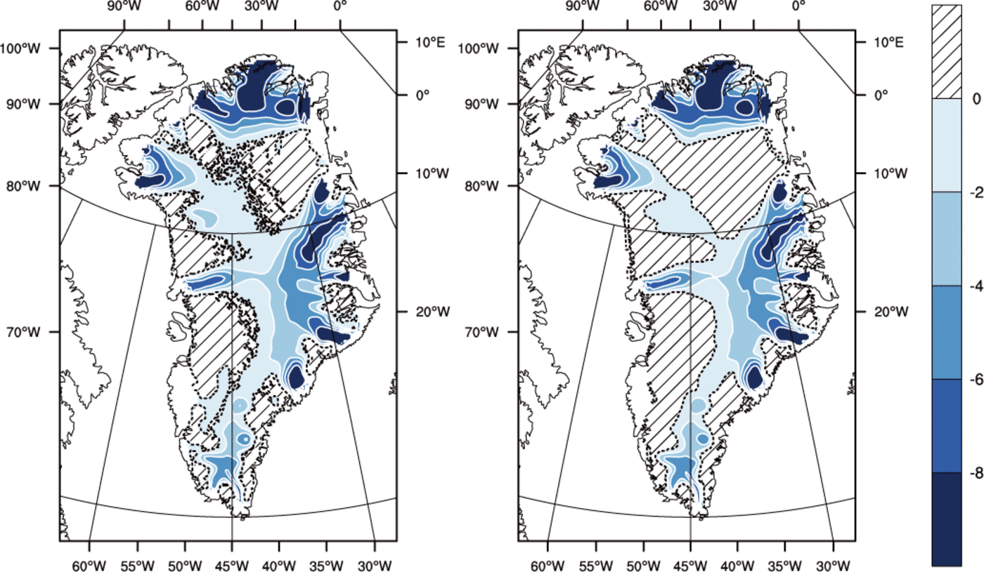
Fig. 6. Pressure-adjusted temperature (?C) at the base for (left) the ENTH run and (right) the TEMP run. Hatched area indicates where the ice is temperate. Contour interval is 2?C. The dashed line is the cold/temperate transition surface.
Table 2. Measurements at the end of each run. Values are averaged over 1000 years
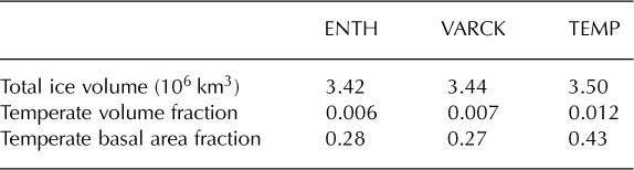
Figure 7 shows that where there is a significant amount of temperate ice in a basal layer, its thickness is greater for TEMP than for ENTH. (By our definition, ice in ENTH and/or VARCK is temperate if H > H s(p) while ice in TEMP is temperate if its pressure-adjusted temperature is within 0.001 K of the melting point.) The greater amount of temperate ice from TEMP, both in volume and extent, may surprise some readers, but there are reasonable explanations. One is that, in parts of the ice in run ENTH, where the liquid water content is significant (e.g. approaching 1%), the greater softness from Eqn (64) implies that shear deformation and associated dissipation heating are enhanced in the bottom of the ice column and do not continue to increase in the upper ice column as the ice is carried toward the outlet. Our result is consistent with those of Greve (1997b), who observes larger temperate volume and thickness from a cold-ice simulation (e.g. Table 2 of Reference GreveGreve, 1997b).
Fig. 7. Thickness of the basal temperate ice layer (m) for (left) the ENTH run and (right) the TEMP run. Contour interval is 25 m. Dotted areas indicate where the bed is temperate but the ice immediately above is cold.
Figure 8 shows that basal melt rates are higher for ENTH than for TEMP. This is explained by recalling the deficiency of cold-ice methods identified in the introduction. Namely, at points where ice temperature has reached the pressure-melting temperature, and where dissipation heating continues, in a cold-ice method the generated water must either be drained immediately or it must be lost as modeled energy, but neither approach is physical. The drainage method used in TEMP is the one described by Reference Bueler and BrownBueler and Brown (2009), in which an elevation-dependent fraction of the generated water is drained immediately as basal melt. This cold-ice method fails to generate as much basal melt as it should, especially near outlets, because it cannot conserve the advected latent heat in an energy-conserving way. Drainage is, in other words, intrinsically more accurate in polythermal methods, even though a drainage model must, necessarily, use a parameterization constrained by only the few existing observations.
Fig. 8. Basal melt rate (mma−1) for (left) the ENTH run and (right) the TEMP run. The dashed line is the cold/temperate transition surface.
Regarding the spatial distribution of basal melt rate seen in both runs, straightforward conservation-of-energy arguments (cf. the back-of-the-envelope calculation in Section 4.6) suggest that in outlet glacier areas the amount of energy deposited in near-base ice by dissipation heating greatly exceeds that from geothermal flux. In any case, these runs used the uniform constant value of 50mWm~2 from EISMINT-Greenland (Reference HuybrechtsHuybrechts, 1998), so spatial variations in our thermodynamical results are not explained by variations in the geothermal flux.
6. Conclusions
Introduction of an enthalpy formulation into an ice-sheet model, replacing temperature as the thermodynamical state variable, allows the model to do a better job of conserving energy. The enthalpy field, Eqn (67), is similar enough to the temperature version to make the replacement process mostly straightforward, but the possibility of liquid water in the ice mixture raises modeling questions that do not arise for cold-ice methods. These issues include choices about temperate ice rheology and intraglacial transport (drainage). One must reformulate the boundary conditions to include possible latent energy sources and sinks at the boundaries. That is, one must allow highly mobile liquid water at the boundaries, both supraglacial runoff and subglacial hydrology, in the conservation-of-energy equations. We have therefore revisited conservation of mass and energy in such thin boundary layers, of necessity. Particular choices of closure relations are, however, generally beyond the scope of this work.
We deduce boundary conditions by a new technique which views jumps of the modeled fields, and thin-layer transport models, as complementary views of the same equation. Basal melt rate, Eqn (47), which is apparently more complete than any such equation found in the literature, arises from this analysis. The thin-layer concept is well suited for incorporation of boundary process models into energy- conserving ice-sheet models.
An enthalpy formulation can be used to simulate either fully cold or fully temperate glaciers, along with the polythermal general case. Neither prior knowledge of the thermal structure nor a parameterization of the cold/temperate transition surface (CTS) is required. Our application to Greenland shows that an enthalpy formulation can be used for continent-scale ice flow problems.
The magnitude and distribution of basal melt rate is a thermodynamical quantity critical to modeling fast ice dynamics in a changing climate. This field can be expected to be more realistic in an energy-conserving enthalpy formulation than in existing temperature-based ice- sheet models.
Acknowledgements
WethankJ. Brown and M. Truffer for stimulating discussions. Comments by the scientific editor, R. Greve, by R. Katz, H. Seroussi, F. Ziemen and an anonymous referee improved the clarity of the manuscript. This work was supported by Swiss National Science Foundation grant No. 200021107480, by NASA grant No. NNX09AJ38G and by a grant of high-performance computing (HPC) resources from the Arctic Region Supercomputing Center as part of the US Department of Defense HPC Modernization Program.
Appendix: Jump Equation with in-Surface Flow and Production
The ‘pillbox’ argument in this appendix, which justifies Eqn (23), is similar to the argument for the jump equation (2.15) of Reference LiuLiu (2002).
As shown in Figure 4, consider a volume, V, with smooth boundary, ∂V, enclosing a portion of a surface, σ. We wish to compute the jump of a scalar field, ψ across σ, but we recognize that this surface is an idealization and that processes like melt and flow occur in some thin layer around σ. We therefore suppose Σ± are smooth oriented surfaces which separate V into disjoint regions V -, V 0 and V +. Region V 0, between Σ- and Σ+, contains a portion of σ and the fast timescale thin-layer processes we wish to model. Let δ0 be the maximum distance between surfaces Σ±, and let w ± denote their normal speeds. Decompose the pillbox boundary, ∂V, into three disjoint components, (∂V)± = V ± ∩ ∂V and (∂V)0 = V 0 ∩ ∂V. Note that the boundary component, (∂V)0, is a ‘band’ with maximum height δ0. Suppose ψ is advected at velocity v, produced at rate π, and experiences an additional non-advective flux, ϕ, in V. General balance Eqn (12) applies in V. Assume that 0 has a finite jump across each surface, Σ±. Following precisely the logic and definitions used to justify eqn (2.15) of Reference LiuLiu (2002),


Fig. 9. A pillbox, V, including a thin active layer volume, V0, which contains a portion of a surface, σ. Equation (23) describes the δ0→ 0 limit in which surfaces Σ∓ bounding V 0 converge to σ.
We will consider the limit δ0 → 0 wherein all (pillbox) dimensions of V normal to Σ± shrink to zero. In this limit, Σ± converge to σ, and, as δ0 → 0, we suppose that Σ± and (∂V)± are all within a normal distance from σ which is some fixed multiple of δ0. As δ0 → 0 we suppose that integrals over V do not disappear, although the volume of V goes to zero, because the thin layer has much larger fluxes and active phase change processes. Specifically we suppose:
-
there is a well-defined area density, λσ, defined in σ so that
(A2)
-
there is an area production density, πσ, defined on σ so that
(A3) -
the boundary component, (∂V)0, becomes a smooth curve, L, in σ, with length element ds; and
-
there is a velocity, vσ, defined in σ and tangent to σ, so that
(A4)


The advective bulk flux, ψv, and non-advective bulk flux, ϕ, combine in the limit, Eqn (A4), to give an advective layer flux λσvσ On the one hand, any flux, qσ, along the layer (units [ψ]m2s-1) can be factored, qσ = λσvσ by introducing a layer density, λb (units [ψ] m), and a velocity, v σ . On the other hand, in the cases appearing in this paper, such layer fluxes are modeled as advective, with a well- defined velocity, in the glaciological literature.
To complete the pillbox argument, split the flux integrals in Eqn (A1) into (∂V)± portions and use Eqns (A2-A4)

where o(δ0) → 0 as δ0 → 0. In the limit, with normal vector, nσ, on σ pointing from V - to V + and with [[ψ]] = [[ψ]]- + [[ψ]]+ denoting the total jump across σ,

(cf. eqn (2.14) of Liu, 2 002).
The divergence theorem allows us to rewrite the line integral as an integral over σ:

The result is an integral over σ only,

Because these arguments can be applied to any part of σ, Eqn (23) follows. If the area density, λσ vanishes then Eqn (A8) implies eqn (2.15) of Reference LiuLiu (2002).


