

Introduction
The dislocation structure and behaviour of glacier ice and ice single crystals grown from the melt have been extensively studied by several investigators. Some workers have examined the effects of plastic deformation (Webb and Hayes, 1967; Fukuda and Higashi, 1969), some the direction of growth (Higashi and others, 1968; Jones, 1970), others impurities (Oguro and Higashi, 1971; Jones and Gilra, 1973), and some the dielectric properties of ice (Itagaki, 1970). There have, however, been few studies into those crystal imperfections in snow or hoar crystals which are grown from water vapour. The direct observation of imperfection in such crystals is important for a knowledge of their growth process or rate. The present author has studied the imperfections in hoar crystals collected from the surface of a large block of snow which had been stored in a cold room for several years.
Thin hexagonal voids formed by the non-uniform refreezing of Tyndall flowers in ice crystals are called “vapour figures” or “negative crystals”. Vapour figures are saturated with water vapour, but do not contain air. Nakaya (1956) studied the formation process of vapour figures in conjunction with the thermal behaviour of Tyndall flowers. He pointed out that some internal lattice strains remained around vapour figures. Krüger and Magun (1955) observed that a Tyndall flower was created at the point where an earlier Tyndall flower had refrozen. He suggested that the internal strain due to refreezing might act as a nucleus for internal melting. Maeno (1968) showed that there were few differences between undeformed samples and those which had been deformed. This author took X-ray topographs in order to reveal the crystal imperfections and local strain fields around a vapour figure.
Concentric dislocations with Burgers vector c <0001> have been observed by Jones (1970) and Oguro and Higashi (1971) in an ice crystal grown from the melt. They found that concentric dislocations were prismatic loops with Burgers vector c <0001>. Long screw dislocations parallel to the crystallographic c-axis have never been observed in ice grown by either the modified Bridgman or the zone-refining method.
In the study reported here two methods are used: X-ray diffraction topography and the divergent Laue technique. Diffraction topography is a very powerful technique for the observation of individual dislocations in a crystal, but in this method only one diffracting plane can be observed at a time. On the other hand, the divergent X-ray Laue technique offers the chance to obtain detailed information about an entire specimen at one time. The behaviour of dislocations in ice subjected to a tensile stress were studied by the use of the divergent Laue technique.
Observations and Results Using X-Ray Diffraction Topography
Experimental procedure
The topographs were taken with a commercial Lang camera (Rigaku-A3), together with a microfocus X-ray generator, which were kept in a cold room at a constant temperature of — 10°C. Mo Kα or Cu Kα radiations were normally used. Most of the photographs of a hoar crystal and an ice crystal which contains a vapour figure were taken on the (1010) and (1120) diffraction plane and scanned over the (0001) surface. Two different diffraction conditions (g vectors <1120> and <0002>) were chosen for each sample in order to observe non-basal dislocations in both a tabular and a glacier ice. The scanning plane was the (1010) prismatic plane in both cases.
Hoar crystals
X-ray topographic observations were carried out on the basal plane of hoar crystals collected from the surface of a large block of snow, which had been kept in a cold room at between —10 and —15°C for several years. The hoar crystals were in the form of hexagonal plates or shallow hexagonal cups 0.5–1 mm thick and 5–10 mm in the major dimension.
Generally, the vapour does not condense uniformly on the hoar crystals, and a symmetrical hexagonal plate was rare.
X-ray topographs of a typical hexagonal plate (Fig. 1A) and a shallow hexagonal cup (Fig. 1B) are shown. Both topographs were taken using the diffraction vector <1010>. Side views of the crystals are also shown in the same figure. Crystal A has the shape of a thin, symmetrical hexagonal plate with a geometrically flat surface. Although various diffracting planes were chosen for the topographs, no dislocation line could be seen in this crystal. A geometrical pattern near the centre of Figure 1A indicates an abrupt change in thickness.

Fig. 1. X-ray topographs of hoar crystals taken in the direction of the diffraction vector <1010> and scanned on (0001) plane. A, dislocation-free thin hexagonal plate. Layer structures can be seen near the centre. B, shallow hopper crystal. Many dislocations can be seen in inner brims, but the outer brims are perfect.
The right-hand topograph (Fig. 1B) shows a cup-shaped crystal which contains many dislocation lines, in contrast to Figure 1A. This suggests that the growth rate of the cup-shaped crystal is greater than that of the plate specimen.
When the extinction condition for dislocation images was taken into account the Burgers vector of most of the dislocations was found to be a/3 <1120>, in accordance with the previous results obtained for single crystals of ice grown from a melt (Webb and Hayes, 1967; Higashi and others, 1968; Jones and Gilra, 1973). As shown in the side-view sketch, the hexagonal cup crystal is composed of several thin hexagonal layers, the growth rate of which may differ from layer to layer.
The dislocation density is large in the layers which grew first, but no dislocation can be seen in the outer layers, in which Pendellösung fringes are clearly seen. The distance between Pendellösung fringes becomes smaller at a corner compared to an edge.
Figure 2 illustrates the X-ray diffraction topographs of another hoar crystal taken in the directions of the diffracting vectors <1010> (Fig. 2A) and <1120> (Fig. 2B). Near the lower edge P where the hoar crystal started to grow, the dislocation density is so large that individual dislocations can only just be distinguished. Away from this point, however, the dislocation density becomes so small that no dislocation line is seen in the upper part of the crystal. Pendellösung fringes are also seen along the periphery of the crystal. This is also evidence that the upper part of the hoar crystal is dislocation- or distortion-free.

Fig. 2. Topographs of a hoar crystal showing stacking-fault images. Diffracting vector are denoted by an arrow “g” and scanned on (0001) plane. Dark triangle images in A are stacking faults which are completely absent in B.
Several triangular dark images can be seen in Figure 2A. The fact that the images are completely absent in Figure 2B strongly suggests that these images are Shockley-type stacking faults lying in the basal plane of the hoar crystal. These stacking faults are of the order of 1 mm in their larger dimension. A stacking fault has never before been observed in pure ice crystals. However, similar images of stacking faults have been observed in NH3-doped ice crystals by Oguro and Higashi (1973) and also in zinc crystals by Fourdeux and others (1960). More than fifty hoar crystals have been observed topographically, no stacking fault image was seen in any other crystal except the one shown in Figure 2.
Dislocation structure around vapour figure
A block of ice containing a hexagonal vapour figure was cut from a large single crystal of ice brought from Mendenhall Glacier in Alaska. A thin rectangular plate of ice 2 mm in thickness with a hexagonal vapour figure at its centre was prepared by chemical polishing (Fig. 3). Since the plane of an hexagonal vapour figure is parallel to the crystallographic basal plane (0001), the crystallographic c-axis of the ice is perpendicular to the largest plane of the ice plate.
X-ray diffraction topographs were taken with four different diffracting vectors <1010>, <1010>, <1120>, and <1120>, for each ice plate sample. Typical example of the topographs in the vicinity of a vapour figure are illustrated in Figures 4A, B, C, and D, in which the diffracting vector is denoted by an arrow. It can be seen in these photographs that the dislocation density is significantly higher along the periphery of the hexagon and that the great majority of dislocations within the hexagon are running toward the vertices or sides of the hexagon. It should be noted that most of the dislocations in the hexagon disappear at the periphery of the vapour hexagon. Similar effects were observed on the other twenty samples used in the present experiments. The configurations of dislocations observed in and around the hexagon are shown in Figure 4E, in which solid straight lines labelled a, b, . . ., i represent bundles of dislocations in the hexagonal area and a broken line indicates the area of high dislocation density. By using the extinction condition for dislocation images, the majority of these dislocations were found to be pure screw, 60°, and 30° dislocations with Burgers vector a/3 <1120>. The X-ray diffraction topographs of another ice plate are illustrated in Figure 5. The illustrations in Figures 4 and 5 strongly suggest that the ice crystal lattice near a vapour figure is heavily distorted by a number of dislocations. Networks of small-angle grain boundaries, that is, arrays of many dislocations, were observed in the vicinity of the vapour figure in Figure 5.

Fig. 3. Rectangular thin plate of ice, prepared by chemical polishing so that the hexagonal vapour figure was placed at the centre of the ice plate. The largest plane of the sample is perpendicular to the crystallographic c-axis.

Fig. 4 Typical configurations around a vapour figure taken with four different diffracting vector as shown in each photograph by an arrow “g” (A–D). E, schematic view of configurations of dislocations in and around the vapour figure. Solid lines labelled with letters a to i represent bundle of dislocations and the broken line indicates an area of high dislocation density.

Fig. 5. Topographs of ice containing a vapour figure taken with a (1010) diffraction vector (A) and a <1120> diffraction vector (B). Both were scanned on the (0001) surface. Small-angle grain boundaries are also to be seen in the vicinity of the vapour figure.
The vapour figures described so far were old, stable ones, because the Mendenhall Glacier samples were cut from ice in which the vapour figures had been originally formed under natural circumstances many years ago and had been stored in a cold room for more than three years before the observations. For a comparison of the dislocation configurations around an old vapour figure with those formed around a new one, vapour figures were prepared by refreezing artificially produced Tyndall flowers.
The X-ray topographs illustrated in Figure 6 were taken immediately after the formation of a new vapour figure. The new vapour hexagon can be seen to the left of centre in each photograph. These dislocation images are very indistinct compared with those around old vapour figures, which suggests that the dislocations are still in an unstable state.

Fig. 6. Topographs of a new vapour figure. Dislocation images are very indistinct compared with those shown in Figures 4 and 5.
Non-basal dislocations in a tabular and a glacier ice
The dislocation structure on non-basal planes of both laboratory-grown ice and glacier ice was studied by X-ray diffraction topography. A tabular ice was grown very slowly at the free surface of water. A tiny disc ice was used as a seed crystal and the growth direction was set to coincide with the crystallographic c-axis. Large single crystals of ice of more than 10 cm in diameter and 5 mm in thickness was obtained when the degree of supercooling was less than 0.5 deg. Most of the basal dislocation of these tabular ice are screw type with Burgers vector a/3 <1120>, confirming the results of the previous workers obtained for glacier ice or ice grown from a melt. It should be noted that straight dislocations parallel to the crystallographic c-axis were only found in the topograph taken with the diffraction vector <0002> and the scanning plane (1010).

Fig. 7. X-ray topographs of a tabular ice (A, B) and a glacier ice (C). A was taken with a <0002> diffraction vector and scanned on (1010) plane. Long screw dislocations with the Burgers vector of c <0001> can be seen. B and C were taken with the diffraction vector of 1120 and scanned on (1010) plane. Stripes parallel to the basal plane are seen in the glacier ice.
Typical features of such dislocations can be seen in Figure 7A. Figures 7A and B are X-ray topographs of the same sample of tabular ice taken with different diffracting conditions, of which the g vectors are shown in each photograph by an arrow and the scanning plane was (1010) in both cases. The dislocation lines completely disappeared when the topograph was taken with the g vector of <1120>, as shown in Figure 7B. The straight dislocation lines crossing over from the top surface to the bottom of the specimen are pure screw dislocations with the Burgers vectors c <0001>. Such long screw dislocations parallel to the c-axis of the order of 2 mm in length have never before been found in a single crystal of ice.
Figure 7B and C are X-ray diffraction topographs of tabular and Mendenhall Glacier ice respectively, both topographs were taken with the diffracting vector <1120>, scanned on the (1010) plane. Dislocations were observed in both ices parallel to the basal plane, but the configurations of the dislocations were different in the two ices. It was noticeable in glacier ice that stripe patterns containing numerous dislocations were arranged parallel to basal planes at intervals of 50–100 μm. These stripes or layered distributions of dislocations may well correspond to the elementary layers observed by an optical method in bent crystals (Nakaya, 1958). The stripe patterns were observed in glacier ice crystals which had never been subjected to any laboratory deformations. The layered distributions of dislocations parallel to the basal plane may have been caused by deformation for long period of time in the glacier.
Observations and Results: Divergent Laue Method
Crystal imperfections
The behaviour of crystal imperfections in ice subjected to tensile stress was studied by the use of the divergent Laue technique (developed by Fujiwara (1968)). In this method, diffraction patterns as well as the transmission pattern from a single crystal are enlarged many times onto an X-ray radiograph, and crystal imperfections can be detected as a fine structure in each of the Laue spots. The divergent Laue technique also offers advantage in that it collects detailed information about various aspects of the crystallinity of a specimen all at the same time. A diagram illustrating this method is shown in Figure 8. A divergent “white” X-ray beam from a microfocus X-ray tube A is diffracted, after passing through a circular slit s, by a thin single crystal E and enlarged Laue spots are obtained on an X-ray film F. A transmission pattern is obtained at the centre of the film by an exposure lasting a few seconds. Double, bright “spectral lines” L in a diffraction pattern from the characteristic X-ray spectrum (Kα and Kβ), are observed in some of the broad Laue spots, and the corresponding decrease in X-ray intensity is observed in a transmission pattern as dark “shadow lines” Q which are generally parallel to the spectral lines L.
Most of the ice used in the present experiment was cut from a large single crystal of ice brought from Mendenhall Glacier, Alaska.
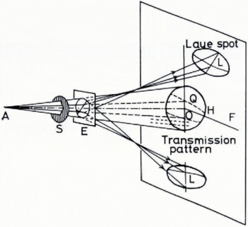
Fig. 8. Schematic diagram for divergent Laue method. A, microfocus X-ray tube; S, circular slit; E, ice crystal; F, film; H, transmission pattern; L, spectral lines; Q, dark shadow lines.
Dislocation density in an ice crystal has generally been found to increase when it is deformed (Webb and Hayes, 1967; Fukuda and Higashi, 1969). In our experiment, however, dislocations in an ice crystal disappeared when it was subjected to a very small deformation. An ice plate, fixed to the goniometer head, was stressed by a weight attached to one end of a string. The other end was attached to the ice which was deformed during the exposure, the extension was measured by a displacement meter. Changes in the positions of Laue spots caused by plastic deformation could be seen when the deformation exceeded one per cent. In our experiment, however, such movements or changes in the position of Laue spots could not be observed as the extension was smaller than this. Figure 9A shows the radiograph of ice immediately before the extension, in which dislocation networks are observed in the three broad Laue spots labelled 2, 7, and 10. These dislocations had completely disappeared after an extension of 0.1 % had been produced by a resolved shear stress of 0.08 bar (8 kN m-2).
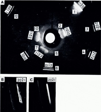
Fig. 9. A, divergent Laue photograph obtained before extension. Dislocation networks are observed in three broad Laue spots labelled 2, 7, and 10. B and C are enlarged diffraction patterns of the (2021) plane before and after extension.
Another remarkable change was found in the diffraction pattern after the small extension. Slightly disturbed fine structures observed in the spectral lines before the extension, which are seen in the spots labelled with 1, 3, 4, 6, and 12, had completely disappeared after an extension of 0.1%.
The enlarged spectral lines shown in Figures 9B and C are the diffraction patterns of the (2020) plane before and after the extension respectively. After the extension, the brightness of the spectral lines became uniform, and black and white lines appeared to cross the spectral line. These black and white lines in the spectral lines must be caused by simultaneous reflection in a perfect crystal (Fujiwara, 1968). The dislocation networks disappeared from some Laue spots and black and white lines (which are evidence of simultaneous reflection in a perfect crystal) were found after a small extension. This strongly suggests that ice crystals attain a greater degree of perfection after a small deformation under a low stress much smaller than the yield stress.
Conclusions
Several hoar crystals having the shape of hexagonal plates were found to be dislocation-free, perfect crystals, due to very slow growth rates. Dislocations and Shockley-type stacking faults were observed in some hoar crystals. The Burgers vector of the majority of basal dislocations was found to be a/3 <1120>. The dislocation density and configuration changed markedly from place to place with the growth rate in one hoar crystal. It was found that the dislocation density along and within a vapour figure is large. Long screw dislocations with the Burgers vector of c <0001> were observed in tabular ice grown on a free surface of supercooled water. Use of the divergent Laue method indicated that an ice crystal could attain a greater degree of perfection as a result of the movement of pre-existing dislocations caused by a small deformation at low stress.
Acknowledgement
The author wishes to express sincere thanks to Professor G. Wakahama for his useful discussion during the preparation of this paper.
Discussion
K. ITAGAKI: I wonder if the Laue figure covers the entire crystal. If not, is it possible that the dislocations might have moved out of the field of observation ?
Y. MIZUNO: The Laue photograph was obtained over an area of 1 cm2. I think it is possible that the dislocations could move out of the field during the observation period.


