1. INTRODUCTION
In recent years, the use of Autonomous Underwater Vehicles (AUV) has rapidly increased since such a vehicle can be operated in the deeper and riskier areas divers cannot reach. In order to complete their mission in the complex underwater environment, AUVs have to face a lot of challenges where two things are extremely important: the robust character of the controller itself and safety consideration under thruster fault conditions.
To deal with the robust control problem, several different approaches have been applied such as adaptive control techniques (Ge and Li, Reference Ge and Li2014; Woods et al., Reference Woods, Bauer and Seto2012; Isermann, Reference Isermann2011), sliding-mode control (Sankaranarayanan and Mahindrakar, Reference Sankaranarayanan and Mahindrakar2009; Soylu et al., Reference Soylu, Buckham and Podhorodeski2008), backstepping control algorithms (Lapierre and Jouvencel, Reference Lapierre and Jouvencel2008; Sui et al, Reference Sui, Tong and Li2014), fuzzy-logic control (Das Sharma et al., Reference Das Sharma, Chatterjee and Rakshit2012; Chen et al., Reference Chen and Tan2013; Liu et al., Reference Liu, Fang, Bian, Zhang and Wang2014) and neural network methods (Zheng and Jun, Reference Zheng and Jun2012; Pan et al., Reference Pan, Lai, Yang and Wu2013).
The sliding-mode method has the outstanding characteristic of including insensitivity to parameter variations, and good rejection of disturbances. These robust characteristics make it quite suitable for robust AUV tracking control. However, one major drawback of the sliding-mode approach is the high frequency of control action (chattering). The backstepping control algorithm is the most commonly used approach for mobile robot tracking control and has been adopted in AUV control systems. The design idea is quite simple and well understood. However, the velocity control law is directly related to the state errors, so large velocities will be generated in a big initial error condition and sharp speed jumps occur during sudden tracking errors.
To resolve the impractical speed jump problem resulting from the backstepping technique, fuzzy control methods and neural network control algorithms are proposed. Fuzzy rule-based tracking control approaches can solve the problem of large initial vehicle velocities. However, the difficult point is the fuzzy rule formulation, which is usually obtained by trial and error-based human knowledge. Neural networks have aptitude for dealing with non-linear problems, and they are envisaged to be beneficial when used on AUVs. Anyhow, the existing neural network-based AUV tracking control algorithms require either online learning or offline training procedures that could be computationally complicated.
The bio-inspired model has been proposed for path planning and tracking control of mobile robots (Luo and Yang, Reference Luo and Yang2008; Yang et al., Reference Yang, Zhu, Yuan and Meng2012). In the work of Zhu et al. (Reference Zhu, Yue and Yan2012), a control method with a bio-inspired model has been applied to the AUV path-following problem. Inspired by the smooth and bounded character of the bio-inspired model, a cascaded control system based on a virtual velocity controller and sliding-mode dynamic controller with bio-inspired model is presented for AUV trajectory tracking control.
Based on the above design, the controller can deal with the tracking control problem well, but there is little discussion about the AUV tracking control with thruster faults. In fact, as an AUV is expected to work in unstructured and complicated environments, it must be liable to faults or failures during underwater missions. Since a thruster is one of the most common and important fault sources (Zhu et al., Reference Zhu, Liu and Yang2008; Zhang and Jiang, Reference Zhang and Jiang2008), once a fault occurs, the AUV cannot accomplish its mission and may even be lost. Due to safety considerations, AUVs are usually designed as an over-actuated system with more thrusters than the desired degree of freedom. If the fault condition is not serious enough, the objective of thruster fault-tolerant control is to perform an appropriate reconfiguration among the functioning thrusters. In such a way, an AUV can still follow the desired task-space trajectories. It is important to mention that in this work we are only concerned about the fault-accommodating allocation and assume that fault information is already known by some fault diagnosis method.
The algorithm of General Inverse (GI) is a common method for the solution of the control reallocation problem (Omerdic and Roberts, Reference Omerdic and Roberts2004; Benosman and Kai-Yew, Reference Benosman and Kai-Yew2009). However, in real-life implementations, the thruster control constraints must be taken into account. The GI approach cannot handle the constrained control problem since the solution of this approach is only based on the attainable command set. To handle such cases where attainable control inputs cannot be allocated, T-approximation (Truncation) and S-approximation (Scaling) methods were proposed (Zhu et al., Reference Zhu, Liu and Hu2011). The solution obtained by the above approximation methods can be contained inside the entire attainable command set, but the magnitude and direction errors caused by approximation still exist and the AUV cannot follow the desired trajectory completely.
For the over-actuated control system, the essence of the system is a constrained optimisation problem and a survey on this problem has been done by Fossen and Jojansen (Reference Fossen and Jojansen2006). Zhu et al. (Reference Zhu, Liu and Hu2011) and Liu et al. (Reference Liu, Wu and Zhu2009) use the Quantum-behaved Particle Swarm Optimisation (QPSO) method to deal with the fault tolerant control of the 7000m manned submarine and URIS AUV model respectively while the fitness value is based on direction error and magnitude error. Inspired by the above design and in order to do a precise reallocation of the fault thrusters, the QPSO method is applied to the control reallocation problem and a thruster Fault Accommodation (FA) method is proposed for the Odin AUV. The maximum norm is selected as the optimisation criterion. Then the thruster fault accommodation method is incorporated with the tracking control problem under thruster fault conditions. The reason for choosing the QPSO approach is the flexibility for online reconfiguration, as for example a change in weight matrix may require the explicit solutions to be recalculated. By this method, the control forces/moments can be reconstructed precisely.
In this paper, a novel control method with thruster FA is proposed for the robust tracking control problem. Different control strategies are used to reallocate the thruster forces when one or more thrusters are completely or partially malfunctioning. For the cases where thrusters are partially malfunctioning, a weighted pseudo-inverse is firstly used to generate the normalised thruster forces. When the normalised thruster forces are out of maximum limit, QPSO is used for the restricted usage of the faulty thruster and to find the solution of the control reallocation problem within the available limits.
This paper is organised as follows. The modelling of the AUV and the controller design is briefly introduced in Section 2. Section 3 describes the Odin control allocation system. Section 4 describes the thruster fault tolerant control and experimental simulations and results are discussed in Sections 4 and 5. Finally, concluding remarks are given in Section 6.
2. MODELLING AND CONTROL
2.1. Modelling in the horizontal plane
In the following, the general control allocation problem will be related with the motion in the horizontal plane. The coordinate systems considered in the horizontal plane are illustrated in Figure 1. The dynamic equation of AUV motion in the horizontal plane can be presented as (Fossen, Reference Fossen2011):
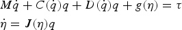 $$\eqalign{& M\dot q + C(\dot q)q + D(\dot q)q + g(\eta ) = \tau \cr & \dot \eta = J(\eta )q} $$
where  $\eta = [\matrix{ x & y & \psi \cr} ]^T $ is the position and orientation state vector with respect to the inertial frame;
  $q = [\matrix{ u & v & r \cr} ]^T $ is the AUV surge, sway and yaw velocity with respect to its body-fixed frame (see Figure 1) (Do et al., Reference Do, Jiang, Pan and Nijmeijer2004);
  $\tau = [\matrix{ {\tau _X} & {\tau _Y} & {\tau _N} \cr} ]^T $ is the control forces and moments of surge, sway and yaw motion. M = diag(m xy, m xy, m ψ) is the inertia matrix including the added mass effects, D = diag(d u, d v, d r) is the hydrodynamic damping including added mass,
  $C = m_{xy} \left[ {\matrix{ 0 & 0 & { - v} \cr 0 & 0 & u \cr v & { - u} & 0 \cr}} \right]$ is the matrix of centrifugal and Coriolis terms,
 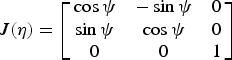 $J(\eta ) = \left[ {\matrix{ {\cos \psi} & { - \sin \psi} & 0 \cr {\sin \psi} & {\cos \psi} & 0 \cr 0 & 0 & 1 \cr}} \right]$ is the spatial transformation matrix between the inertial frame and the AUV's body-fixed frame.

Figure 1. Mathematical model of AUV in the horizontal plane.
2.2. Filter-designed cascaded controller
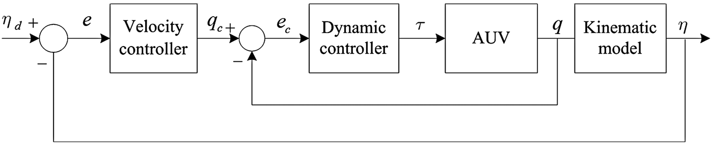
The basic control architecture of the system is illustrated in Figure 2. The design of the hybrid control strategy consists of two parts: (1) an outer loop virtual velocity controller using position and orientation state errors; (2) an inner loop sliding-mode controller using velocity state vector.
Figure 2. The scheme of the proposed AUV tracking control system (without thruster fault).
2.2.1. Filter-designed velocity controller
For AUV motion control in the horizontal plane, the desired state of a reference vehicle is described as 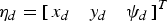 ${\bi \eta} _d = [\matrix{ {x_d} & {y_d} & {\psi _d} \cr} ]^T $ and
  ${\bi q}_d = [\matrix{ {u_d} & {v_d} & {r_d} \cr} ]^T $. The actual state of the AUV is represented by
 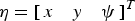 ${\bi \eta} = [\matrix{ x & y & \psi \cr} ]^T $,
 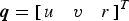 ${\bi q} = [\matrix{ u & v & r \cr} ]^T $. The objective of the tracking controller is to make the AUV follow the known trajectory by controlling the forward and angular velocities. Thus the error
  ${\bi e} = \matrix{ {[e_x} & {e_y} & {e_\psi } \cr} ]^T $ between desired state and actual state converges to zero.
  ${\bi e} = {\bi \eta} _d - {\bi \eta} = \matrix{ {[e_x} & {e_y} & {e_\psi } \cr} ]^T $ is the tracking error in the inertial frame. The detailed description can be seen in Figure 3.
Figure 3. Tracking control formulation.
The auxiliary velocity controller based on the backstepping approach can be defined as
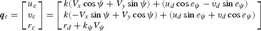
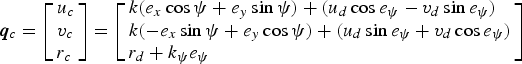 $${\bi q}_c = \left[ \matrix{u_c \hfill \cr v_c \hfill \cr r_c \hfill} \right] = \left[ \matrix{k(e_x \cos \psi + e_y \sin \psi ) + (u_d \cos e_\psi - v_d \sin e_\psi ) \hfill \cr k( - e_x \sin \psi + e_y \cos \psi ) + (u_d \sin e_\psi + v_d \cos e_\psi ) \hfill \cr r_d + k_\psi e_\psi \hfill} \right]$$
where k, k ψ are constant coefficients.
Through deep analysis of Equation (2), the auxiliary speed is directly related to the tracking errors. As mentioned in Section 1, this typical backstepping method will undoubtedly produce sharp speed jumps. In order to resolve the speed jump and control constraint problem, a bio-inspired model is added in the controller to design the auxiliary velocity. To simplify the equation, the bio-inspired model can infer the following form (Yang et al., Reference Yang, Zhu, Yuan and Meng2012)
 $${\dot V_i} = - A{V_i} + (B - {V_i})f({e_i}) - (D + {V_i})g({e_i})$$
where f(e i) = max (e i, 0), g(e i) = max (−e i, 0), A, B, D are positive constants. The bio-inspired model is a continuous differential equation and can also be regarded as a low pass filter. The system's output V is guaranteed to stay in a region [−D, B] for any excitatory and inhibitory inputs. In this paper, the tracking errors e are chosen as the inputs of the bio-inspired model, while the outputs V i (i = x, y, ψ) will replace the tracking errors e.
The proposed filter designed velocity controller is given by:
 $${\bi q}_c = \left[ \matrix{u_c \hfill \cr v_c \hfill \cr r_c \hfill} \right] = \left[ \matrix{k(V_x \cos \psi + V_y \sin \psi ) + (u_d \cos e_\psi - v_d \sin e_\psi ) \hfill \cr k( - V_x \sin \psi + V_y \cos \psi ) + (u_d \sin e_\psi + v_d \cos e_\psi ) \hfill \cr r_d + k_\psi V_\psi \hfill} \right]$$
where k, k ψ are the same parameters as in Equation (2). Due to the shunting characteristics of the bio-inspired model, the output of the bio-inspired model is bounded in a finite interval and smooth without any sharp jumps when inputs have sudden changes.
2.2.2. Dynamic controller
Sliding-mode control is applied to extend kinematic control to the dynamic control. It is a former work by the authors (Sun et al., Reference Sun, Zhu and Yang2014) and a brief description is given as follows.
As a rule, sliding-mode control can be divided into two parts. First, define a sliding manifold s. Second, find a control law to move toward the sliding manifold. The sliding manifold (or filter velocity error) can be chosen as (Slotine and Li, Reference Slotine and Li1991):
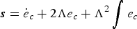 $${\bi s} = \dot e_c + 2\Lambda e_c + \Lambda ^2 \int {e_c} $$
where ec = qc − q is the velocity error between the auxiliary velocity and the actual AUV velocity. As a derivation of Equation (5) the equivalent control law can be written as
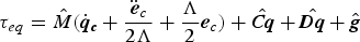 $${\bi \tau} _{eq} = \hat M(\dot{\bi q}_{\bi c} + \displaystyle{{{\ddot{\bi e}_c}} \over {2\Lambda}} + \displaystyle{\Lambda \over 2}{\bi e}_c ) + \hat{\bi Cq} + \hat{\bi Dq} + \hat{\bi g}$$
where  $\hat M{\rm,} \,\hat{\bi C}{\rm,} \,\hat{\bi D}{\rm,} \,\hat{\bi g}$ are estimated terms. To eliminate the chattering problem caused by the conventional discontinuous term, an adaptive term is added in the control law to replace the switching term
 $${\bi \tau} _{ad} = {\tilde {\bi \tau}} _{est} + (K + \displaystyle{{\hat{\bi C}} \over {2\Lambda}} ){\bi s}$$
 $\tilde \tau _{est} $ is an adaptive term that estimates the lumped uncertainty vector
  $\tilde \tau $. The estimation of the lumped uncertainty vector is proposed to follow:
 $${\dot {\tilde{\bi \tau}}} _{est} = \Gamma {\bi s}$$
The total control law can be defined as
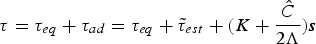 $${\bi \tau} = {\bi \tau} _{eq} + {\bi \tau} _{ad} = {\bi \tau} _{eq} + {\tilde{\bi \tau}} _{est} + (K + \displaystyle{{\hat C} \over {2\Lambda}} ){\bi s}$$
3. CONTROL ALLOCATION OF ODIN
In this paper, our work mainly focuses on the filter-designed cascaded tracking control with fault thruster reallocation in the horizontal plane. In order to demonstrate the cascaded tracking control effectiveness, an example of Odin AUV (Do et al., Reference Do, Jiang, Pan and Nijmeijer2004) tracking control is discussed. A brief sketch of the Odin vehicle's horizontal thruster distribution is shown in Figure 4. ODIN has four horizontal thrusters fixed in symmetrical layout, denoted as iHT, i ∈ [1, 4], and four vertical thrusters. The thruster configuration of Odin enables direct control of surge, sway and yaw control in the horizontal plane. This construction puts redundancy into the system in case of thruster failure. Thruster fault tolerant control in the horizontal plane will be discussed in this paper.
Figure 4. Thruster Distribution.
The total vector of propulsion forces and moments in the horizontal plane can be written as:
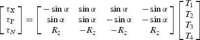 $$\left[ \matrix{\tau _X \hfill \cr \tau _Y \hfill \cr \tau _N \hfill} \right] = \left[ {\matrix{ { - \sin \alpha} & {\sin \alpha} & {\sin \alpha} & { - \sin \alpha} \cr {\sin \alpha} & {\sin \alpha} & { - \sin \alpha} & { - \sin \alpha} \cr {R_z} & { - R_z} & { - R_z} & {R_z} \cr}} \right]\left[ \matrix{T_1 \hfill \cr T_2 \hfill \cr T_3 \hfill \cr T_4 \hfill} \right]$$
where  $[\matrix{ {\tau _X} & {\tau _Y} & {\tau _N} \cr} ]^T $ is the total forces/moments acting on the AUV centre of mass,
  $[\matrix{ {T_1} & {T_2} & {T_3} & {T_4} \cr} ]^T $ is the forces of the four thrusters individually, R z = 0·4816, α = 45°. By simplification, Equation (10) can be written as:
 $$\left[ \matrix{\displaystyle{{\tau _X} \over {\tau _{Xm}}} \hfill \cr \displaystyle{{\tau _Y} \over {\tau _{Ym}}} \hfill \cr \displaystyle{{\tau _N} \over {\tau _{Nm}}} \hfill} \right] = \left[ {\matrix{ { - \displaystyle{1 \over 4}} & {\displaystyle{1 \over 4}} & {\displaystyle{1 \over 4}} & { - \displaystyle{1 \over 4}} \cr {\displaystyle{1 \over 4}} & {\displaystyle{1 \over 4}} & { - \displaystyle{1 \over 4}} & { - \displaystyle{1 \over 4}} \cr {\displaystyle{1 \over 4}} & { - \displaystyle{1 \over 4}} & {\displaystyle{1 \over 4}} & { - \displaystyle{1 \over 4}} \cr}} \right]\left[ \matrix{T_1 {\rm /}T_m \hfill \cr T_2 {\rm /}T_m \hfill \cr T_3 {\rm /}T_m \hfill \cr T_4 {\rm /}T_m \hfill} \right]$$
where τ Xm, τ Ym, τ Nm represents the maximum values of force and moment vectors for Odin AUV respectively, T m represents the max force of an individual thruster.
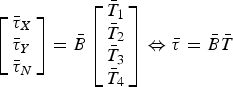 $$\left[ \matrix{\bar \tau _X \hfill \cr \bar \tau _Y \hfill \cr \bar \tau _N \hfill} \right] = \bar B\left[ \matrix{\bar T_1 \hfill \cr \bar T_2 \hfill \cr \bar T_3 \hfill \cr \bar T_4 \hfill} \right] \Leftrightarrow \bar \tau = \bar B\bar T$$
where  $\bar B{\rm =} \left[ {\matrix{ { - \displaystyle{1 \over 4}} & {\displaystyle{1 \over 4}} & {\displaystyle{1 \over 4}} & { - \displaystyle{1 \over 4}} \cr {\displaystyle{1 \over 4}} & {\displaystyle{1 \over 4}} & { - \displaystyle{1 \over 4}} & { - \displaystyle{1 \over 4}} \cr {\displaystyle{1 \over 4}} & { - \displaystyle{1 \over 4}} & {\displaystyle{1 \over 4}} & { - \displaystyle{1 \over 4}} \cr}} \right]$,
  $ - 1 \le \bar \tau _j \le 1,\,j = X,Y,N$,
  $ - 1 \le \bar T_i \le 1,$
 $i = 1,2,3,4$.
4. THRUSTER FAULT TOLERANT CONTROL
In this section, the tracking control problem is extended to the thruster fault condition. When a thruster fault happens, thruster accommodation among the functioning thrusters is adopted in the system. A general sketch of tracking control with thruster fault is given in Figure 5. Thruster fault accommodation of an AUV such as Odin has been discussed in Sarkar et al. (Reference Sarkar, Podder and Antonelli2002) and Andonian et al. (Reference Andonian, Cazzaro and Invernizzi2010). Unlike the former discussion only about a totally broken thruster, in this section, the thruster fault tolerant control strategy will be divided into two main categories: thruster completely malfunctioning and thruster partially malfunctioning. In this work, the fault condition is assumed to be known by some fault diagnosis method. The main work is to propose a fault accommodation strategy to generate the demanded control signal among the functioning thrusters. The block diagram of thruster fault accommodation control for the specific Odin AUV can be found in Figure 6 and it should be noted that this control strategy can be applied to different kind of AUVs in a similar way.
Figure 5. A general tracking control system with thruster fault.
Figure 6. The block diagram of thruster fault accommodation control.
4.1. Thrusters completely malfunctioning
The thruster configuration matrix  $\bar B$ with no fault is given in Equation (12). When only one thruster (the ith thruster) is faulty, delete the corresponding column of thruster configuration matrix
  $\bar B$, and then
  $\bar B$ turns into a 3 × 3 matrix
  $\bar B_i $. This leads to a unique 3 × 1 solution vector
  $\bar T$ (the ith broken thruster output
  $\bar T_i $ is deleted from the vector). The thruster solution can be given by simple inverse
 $$\bar T = \bar B_i ^{ - 1} \bar \tau $$
If the solution of Equation (13) is out of the limitation boundary  $ - 1 \le \bar T \le 1$, the T-approximation or S-approximation method is used to ensure the limitation and optimisation algorithms cannot be applied in this case.
4.2. Thruster partly malfunctioning
4.2.1. Hybrid thruster reconfiguration strategy
As can be seen from the block diagram of thruster fault tolerant control in Figure 6, a hybrid thruster reconfiguration strategy is proposed by using the weighted pseudo-inverse and QPSO. The hybrid thruster control reconfiguration approach can be described as follows:
First, the desired control signal  $\bar \tau _d $ is calculated by the weighted pseudo-inverse to generate the thruster force
  $\bar T$. If all of the normalised thruster output is in the range of saturation point
  $ - 1 \lt \bar T_i \lt 1$, the QPSO method is not needed in this case. If any of the normalised thruster input is out of the saturation range
  $ - 1 \lt \bar T_i \lt 1$, then QPSO method is applied so that the demanded controller output can be reallocated among the functioning thrusters.
4.2.2. Weighted pseudo-inverse method
In the former section, the case of one thruster totally broken is considered. But a large proportion of the cases will involve a thruster in a partially malfunctioning condition. Here we assume that the fault diagnosis processes have already been completed (Zhu and Sun, Reference Zhu and Sun2013). Accordingly, this paper focuses on the thruster fault accommodation and discusses the tracking control for continuing the mission.
In order to account for the faulty thrusters, a diagonal weighting matrix can be used for the later thruster accommodation. The diagonal weighting matrix can be defined as
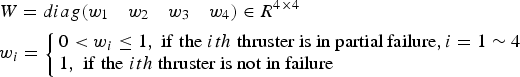 $$\eqalign{& W = diag({{{w_1}} \quad {{w_2}} \quad {{w_3}} \quad {{w_4}}} ) \in {R^{4 \times 4}} \cr & {w_i} = \left\{ \matrix{0 \lt {w_i} \le 1,\;{\rm if \;the}\;ith\;{\hbox{thruster is in partial failure}},i = {\rm 1}\sim{\rm 4} \hfill \cr 1,\;{\rm if \; the}\;ith\;{\hbox{thruster is not in failure}} \hfill} \right.}$$
where the weighting coefficient w i represents the fault degree of the thruster. The bigger the w i, the smaller the fault and vice versa.“1” and “0” in the weighting matrix represent the upper and lower saturation limits of faulty thrusters to meet the available thrust capacity. Generally speaking, propeller thrust and rotational speed is a complex nonlinear relationship. Here, for simple consideration, it can be regarded as a linear relation, so the weight coefficient can be simply described as
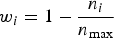 $$w_i = 1 - \displaystyle{{n_i} \over {n_{\max}}} $$
where n i is the actual rotational speed and n max is the ideal rotational speed.
The block diagram of the control reconfiguration is shown in Figure 5. It is clear that the control allocation matrix can be rewritten as:
 $$\bar \tau = \bar BW\bar T$$
If the thruster is partly malfunctioning with the given weighting matrix in Equation (14), the horizontal thruster forces for the desired horizontal motions can be obtained by weighted pseudo-inverse:
 $$\bar T = W^{ - 1} \bar B^T (\bar BW^{ - 1} \bar B^T )^{ - 1} \bar \tau $$
The weighted pseudo-inverse method is a commonly used control allocation method to deal with the thruster fault accommodation problem of AUV systems. Two approximation methods (truncation or scaling) are used to ensure that the normalised thruster forces are able to satisfy the constraints ( $ - 1 \le \bar T \le 1$). However, by truncation or scaling, the reconstruction control forces may not equal the desired forces τ R ≠ τ. Generally, the number of thrusters in the Odin AUV is more than the minimum required to produce the desired motion, so the thruster solution is not unique. In order to extract a most appropriate solution, QPSO with constraints is used to find the optimum control vector in this paper.
4.2.3. Quantum-behaved Particle Swarm Optimisation (QPSO)
In the QPSO model, the state of a particle is depicted by wave function ψ (x,t) instead of position and velocity. The dynamic behaviour of the particle is widely divergent from the particle in traditional PSO systems since the exact values of x and V cannot be determined simultaneously. It can only learn the probability of the particle's appearance in position x from the probability density function |ψ (x,t)|2. By using this function, the potential field where the particle lies can be determined. The particles move according to the following iterative equation:
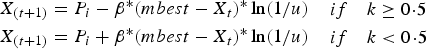 $$\eqalign{& X_{(t + 1)} = P_i - \beta {^\ast}(mbest - X_t ){^\ast}\ln (1/u)\matrix{ {} & {if} & {k \ge 0\!\cdot\!5} \cr} \cr & X_{(t + 1)} = P_i + \beta {^\ast}(mbest - X_t ){^\ast}\ln (1/u)\matrix{ {} & {if} & {k \lt 0\!\cdot\!5} \cr}} $$
where
 $$P_i = \varphi {^\ast}pbest_i + (1 - \varphi ){^\ast}gbest_i $$
 $$mbest = \displaystyle{1 \over N}\sum\limits_{i = 1}^N {\,pbest_i} $$
mbest is the mean best position defined as the mean of all the best positions of the population, k, u and ϕ are random numbers distributed uniformly on [0, 1] respectively. Considering that the iteration number and population size are common parameters in every evolutionary algorithm, the contraction-expansion coefficient β is the only parameter in the QPSO algorithm. It can be tuned to control the convergence speed of QPSO method.
The objective function is defined by the l ∞ norm of the thruster force. The l ∞ norm of the thruster force manifold  $\bar T = \left[ {\matrix{ {\bar T_1} & {\bar T_2} & {\bar T_3} & {\bar T_4} \cr}} \right]^T $ is defined as
 $$\Vert {\bar T} \Vert _\infty = \max \{\vert{\bar T_1}\vert \quad \vert{\bar T_2}\vert \quad \vert{\bar T_3}\vert \quad \vert {\bar T_4}\vert \} $$
 For equation  $\bar \tau = \bar BW\bar T$, it can be written as
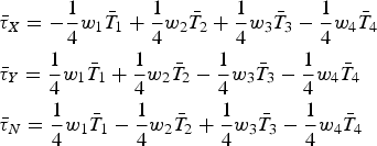 $$\eqalign{& \bar \tau _X = - \displaystyle{1 \over 4}w_1 \bar T_1 + \displaystyle{1 \over 4}w_2 \bar T_2 + \displaystyle{1 \over 4}w_3 \bar T_3 - \displaystyle{1 \over 4}w_4 \bar T_4 \cr & \bar \tau _Y = \displaystyle{1 \over 4}w_1 \bar T_1 + \displaystyle{1 \over 4}w_2 \bar T_2 - \displaystyle{1 \over 4}w_3 \bar T_3 - \displaystyle{1 \over 4}w_4 \bar T_4 \cr & \bar \tau _N = \displaystyle{1 \over 4}w_1 \bar T_1 - \displaystyle{1 \over 4}w_2 \bar T_2 + \displaystyle{1 \over 4}w_3 \bar T_3 - \displaystyle{1 \over 4}w_4 \bar T_4} $$
One inverse function can be given as
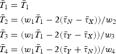 $$\eqalign{& \bar T_1 = \bar T_1 \cr & \bar T_2 = (w_1 \bar T_1 - 2(\bar \tau _N - \bar \tau _X ))/w_2 \cr & \bar T_3 = (w_1 \bar T_1 - 2(\bar \tau _Y - \bar \tau _X ))/w_3 \cr & \bar T_4 = (w_1 \bar T_1 - 2(\bar \tau _Y + \bar \tau _N ))/w_4} $$
where w 1, w 3, w 4 ≠ 0. Then based on the new Equation (23), the optimisation problem can be simplified into one single parameter tuning under the objective criterion Equation (21). This solution can reduce the computation cost and select the most suitable control force in the solution space. While in the case of more thrusters, multi parameter tuning is favourable, this is out of the scope of this paper.
After thruster normalisation, [−1,1] are the thruster saturation limits, so the constrained optimisation problem becomes to acquire the smallest l ∞ norm thrust value as the feasible solution. The formula's expression can be given as follows:
 $${\rm minimise}\, {\Vert{\bar T} \Vert_\infty },\; {\rm subject \; to} \; \bar \tau = \bar BW\bar T, - 1 \le {\bar T_i} \le 1,i = 1 \sim 4.$$
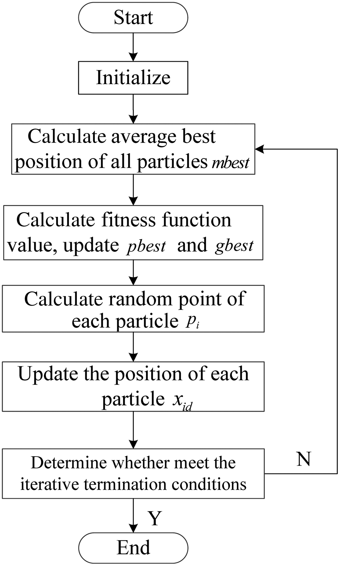
The flow chart of QPSO is shown in Figure 7.
Figure 7. The flow chart of QPSO.
4.3. Simulation study
In order to show the superior performance when QPSO is applied to the hybrid thruster reconfiguration strategy, two simple comparison studies are conducted in this section. This will show the efficiency of this control allocation strategy.
4.3.1. The One Thruster Fault Case
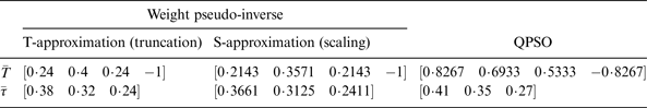
Assume that the first thruster (1HT thruster) is detected as faulty and its corresponding weight value of fault state w 1 is 1/2, so  $W = {\rm diag}(\matrix{ {{\rm 1/2}} & {\rm 1} & {\rm 1} & {\rm 1} \cr } {\rm )}$.
Let the given motion control forces/moments  $\bar \tau = [{0\!\cdot\!41} \quad {0\!\cdot\!35} \quad {0\!\cdot\!27} ]$ for thruster configuration of Odin AUV. The weighted pseudo-inverse solution
  $\bar T = [{0\!\cdot\!24} \quad {0\!\cdot\!4} \quad {0\!\cdot\!24} \quad {- 1\!\cdot\!12} ]$ is unfeasible because
  $\bar T_4 \gt 1$. Then T-approximation is given by
  $\bar T = [{0\!\cdot\!24} \quad {0\!\cdot\!4} \quad {0\!\cdot\!24} \quad {- 1}]$, according to Equation (16), the reconfiguration forces are
  $\bar \tau _R = [\matrix{ {0\!\cdot\!38} \quad {0\!\cdot\!32} \quad {0\!\cdot\!24}} ]$. The S-approximation is given by
  $\bar T = [{0\!\cdot\!2143} \quad {0\!\cdot\!3571} \quad {0\!\cdot\!2143} \quad {\rm - 1} ]$, then
  $\bar \tau _R = [{0\!\cdot\!3661} \quad {0\!\cdot\!3125} \quad {0\!\cdot\!2411}]$. In contrast, the solution obtained by the QPSO algorithm T̅ = 0·8627 0·6933 0·5333 −0·8267 is feasible without any approximation because
  $\bar T$ is limited in [−1, 1] during the process of searching for a solution in the QPSO algorithm and the corresponding
  $\bar \tau _R = \bar BW\bar T = [{0\!\cdot\!41} \quad {0\!\cdot\!35} \quad {0\!\cdot\!27}] = \bar \tau $.
From Table 1, it can be seen that the control vector obtained by the QPSO algorithm can reallocate the thruster forces reasonably compared with the method of weighted pseudo-inverse and can precisely meet the desired control forces/moments  $\bar \tau = [{0\!\cdot\!41} \quad {0\!\cdot\!35} \quad {0\!\cdot\!27}]$ as the original state. By normalisation of the reconfiguration forces and moments in Table 1, the comparison result is illustrated in Figure 8(a) which clearly shows the reconfiguration effect.
Figure 8. Comparison of different types of fault case.
Table 1. The results of first thruster fault case.
4.3.2. The Two Thruster Fault Case
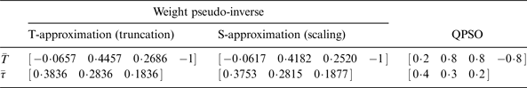
Assume that the second and third thrusters (2HT and 3HT thruster) are detected as faulty, and the corresponding weight value of fault state w 2 = 3/4, w 3 = 1/2 and weight matrix  $W = diag(\matrix{ 1 & {3/4} & {1/2} & 1 \cr} )$. Let the original state
  $\bar \tau = [\matrix{ {0\cdot4} & {0\cdot3} & {0\cdot2} \cr} ]$. The experimental results are shown in Table 2 and are mostly the same result as the one fault case. By normalisation of the reconfiguration forces and moments in Table 2, the comparison result is illustrated in Figure 8(b) which clearly shows the reconfiguration effect.
Table 2. The results of second and third thruster fault case.
The solutions obtained by different methods could perform the appropriate configuration, but the solutions obtained by weighted pseudo-inverse still have some error in magnitude, while the QPSO algorithm can preserve the original magnitude within thruster limitations. It should be noted that l ∞ norm thrust allocation is not energy minimisation but a solution to minimise all the thruster forces in the solution space so that the AUV can have more manoeuvring ability.
5. SIMULATION AND DISCUSSION
In this section, simulation studies are performed to demonstrate the effectiveness of the proposed tracking control method with thruster allocation approaches. The AUV system considered in the simulations is the Odin model discussed in Section 3.
5.1. Circular tracking
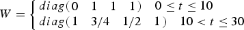
In this study, the filter-designed method with thruster faults is applied to the trajectory tracking. Assume that the first thruster is totally broken in the first 10 s, then in the 10 s–30 s assume that second and third thrusters (2HT and 3HT thruster) are detected as partially faulty, and the corresponding weight value of fault state w 2 = 3/4, w 3 = 1/2. The weight matrix can be written as:
 $$W = \left\{ \matrix{diag(\matrix{ 0 & 1 & 1 & 1 \cr } )\quad 0 \le t \le 10 \hfill \cr diag(\matrix{ 1 & {3/4} & {1/2} & 1 \cr } )\quad 10 \lt t \le 30 \hfill} \right.$$
The AUV starts at posture (−0·5, −2, 0), while the desired initial AUV posture is (0, −1, 0). Thus the initial posture error is (−0·5, −1, 0). Time varies from 0 to 30 s. The desired state of AUV is x d (t) = sin (0·5t), y d (t) = −cos (0·5t), ψ d (t) = 0·5t.
In order to show the efficiency of the fault accommodation method, the filter-designed tracking method without fault accommodation is conducted as a comparison study. Figures 9–11 show the simulation results of the circle tracking. The red solid lines indicate the filter-designed tracking method with fault accommodation results, and the blue solid lines are the filter-designed method without fault accommodation. Figure 9 gives the tracking control results of the filter-designed method with and without fault accommodation on the same condition. Figure 10 gives the tracking errors and the normalised thruster control force  ${\bar {\bi T}}$ of trajectory tracking is shown in Figure 11.
Figure 9. The tracking result using filter-designed method with and without fault accommodation.
Figure 10. The tracking errors using filter-designed method with and without fault accommodation.
Figure 11. The normalised thruster forces using filter designed method with and without fault accommodation.
In the first 10 s, the first thruster is assumed to be totally broken, and then the thruster reallocation method is given in Equation (13). The T-approximation method is used to ensure the limitation if the solution of Equation (13) is out of the limitation boundary  $ - 1 \le {\bar{\bi T}} \le 1$. In 10 s–30 s, the second and third thrusters (2HT and 3HT thruster) are detected as partially faulty. Then the weighted pseudo-inverse method given in Equation (17) is used to generate the thruster control signal. If any of the thruster control signal
  $\bar T_i $ is out of the limitation range [−1, 1], the QPSO method is used to reconfigure the thruster control forces.
From Figures 9 and 10, it can be clearly seen that the filter-designed tracking method with fault accommodation can quickly achieve the desired trajectory while the tracking method without fault accommodation cannot accomplish the tracking mission since the reconfigured control forces/moments cannot meet the desired control forces/moments  $\bar \tau \ne \bar \tau _d $. The fault accommodation method can achieve perfect tracking after the first 5 s. After 10 s, the fault thruster situation changes, therefore it needs an adjustment process while the filter-designed tracking method with fault accommodation can still achieve smooth tracking control. Where there is no fault accommodation method, since no fault tolerant control strategy is added, the tracking performance is quite poor so that it cannot achieve the assigned tracking tasks. The change of thruster fault case can also be reflected in the normalised thruster control forces in Figure 11. At time 10 s, the fault accommodation method can reallocate the control forces rapidly and achieve precise tracking while not having a fault accommodation method does not achieve the desired control forces.
5.2. Sinusoid tracking
Circular tracking is a traditional research scenario where the desired trajectory is generated with constant velocity, but sometimes the desired trajectory is generated with variable velocities and it will be more difficult to solve the tracking control problem. In order to show the superiority of the fault accommodation method, in this section, the sinusoid tracking will be studied and the parameter setting is the same as the former section. The AUV starts at posture (−0·5, −2, 0), while the desired initial robot posture is (0, 0, 1·3734). Thus the initial posture error is (0·5, 2, 1·3734). Time varies from 0 to 60 s. The desired state of the AUV is x d (t) = 0·2t, y d (t) = 2sin(0·5t),  $\psi _d (t) = a\tan 2(\displaystyle{{\dot y_d} \over {\dot x_d}} ).$ The fault tolerant control strategy is the same as Section 4. The weight matrix can be written as:
 $$W = \left\{ \matrix{diag(\matrix{ 0 & 1 & 1 & 1 \cr } )\quad 0 \le t \le 10 \hfill \cr diag(\matrix{ 1 & {3/4} & {1/2} & 1 \cr } )\quad 10 \lt t \le 30 \hfill} \right.$$
Figures 12–14 show the simulation results of the sinusoid tracking. The red solid lines indicate the filter designed tracking method with fault accommodation results, and the blue solid lines are the filter-designed method without fault accommodation. Figure 12 gives the tracking control results of filter-designed method with and without fault accommodation on the same condition. Figure 13 shows the tracking errors of the filter-designed method with and without fault accommodation. The normalised thruster control force of trajectory tracking is shown in Figure 14.
Figure 12. The tracking result using filter-designed method with and without fault accommodation.
Figure 13. The tracking errors using filter-designed method with and without fault accommodation.
Figure 14. Normalised thruster control force using filter-designed method with and without fault accommodation.
From Figures 13 and 14 it can be clearly seen that the proposed method with fault accommodation can quickly achieve the desired trajectory while the tracking method without fault accommodation cannot reach the trajectory and move along it in a limited time. For the fault accommodation method, it can achieve quite good tracking results after the first 10 s. Due to the varying velocities, there still exist small tracking errors, but they remain within an acceptable range. When the fault thruster situation changes after 10 s, the filter-designed tracking method with fault accommodation can still have a smooth and continuous control without performance loss. The change of thruster fault case can also be reflected in the normalised thruster forces. After 10 s, fault accommodation method can reallocate the control forces rapidly and achieve precise tracking while the method with no fault accommodation has to catch the desired control forces smoothly.
5.3. Comparison with other methods
From the former simulation results, it can be concluded that the proposed method is an efficient tool for fault tolerant tracking control. In this part, in order to show the reason to choose the cascaded control method for tracking control, a comparison study between the proposed method and some benchmark methods are given. Here, an adaptive method and a neural network method are selected since they are commonly used in robotic control and a simple introduction is given as follows:
5.3.1. Adaptive method
A classical adaptive algorithm (hereinafter referred to as adaptive method) first proposed by Slotine and Li (Reference Slotine and Li1991) was used as a comparison study. The control law is given as:
 $${\bi \tau} = \Phi (\dot v_r, v_r, v,\eta ){\hat {\bf \theta}} - {\bf J}^T ({\bf \eta} )K_d {\bf s}$$
The adaptive law of  ${\hat {\bf \theta}} $ can be chosen as:
 $${\dot {\hat {\bf \theta}}} = - \Gamma \Phi ^T (\dot v_r, v_r, v,\eta ){\bf J}^{ - 1} ({\bf \eta} ){\bf s}$$
where  ${\hat {\bf \theta}} $ is the estimated parameter vector and K d, Γ are positive constants. Detailed description of this method can be found in Slotine and Li (Reference Slotine and Li1991).
5.3.2. Neural network (NN) method
Neural network control for robotic system is a popular design and here a typical neural network design (Radial Basis Function) was used as a comparison study. The control law is given as:
 $$\tau _\eta = \hat f\,(h) + K_v s - \alpha $$
where the neural network function estimate in the controller as 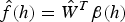 $\hat f(h) = \hat W^T \beta (h)$ and a detailed description of this method be found in Jagannathan and Galan (Reference Jagannathan and Galan2003).
The AUV starts at posture (0, −1·5, 0), while the desired initial robot posture is (0, −1, 0). Thus the initial posture error is (0, 0·5, 0). Time varies from 0 to 30 s. The desired state of AUV is x d (t) = sin(0·5t), y d (t) = −cos(0·5t), ψ d (t) = 0·5t. The controller parameter setting for the three methods are given as follows:
1. The proposed method: K = 20, k = 2, k ψ = 2, A = 2, B = 1, D = 1
2. The adaptive method: K d = 20, Γ = 1
3. The neural network method: K p = 9, K v = 6, the NN was not trained offline and the weights were initialised at zero.
It can be concluded that in order to give a satisfactory tracking result, the parameters cannot be too small, or the convergence rate will be too slow. The parameters cannot be too large, or control inputs will be big enough to exceed the thruster limits. The parameter values are selected experimentally and have the same order of magnitude in a general way.
Figure 15 shows the final tracking control results under the different methods: the proposed method, adaptive method and NN method. From the simulation results, it is clear to see that the proposed method has superior performance over the other two methods. Since the adaptive method and NN design have both updated a process, it will cause a computation burden and the weight tuning in the very beginning is a major problem in causing slow convergence.
Figure 15. Comparison study with other control methods.
6. CONCLUSION
In this paper, a filter-designed cascaded controller for the Odin Autonomous Underwater Vehicle (AUV) with thruster fault tolerant control is proposed. Firstly, a filter-designed cascaded tracking control is proposed to deal with robust tracking control. Secondly, a different control strategy for various thruster fault cases is presented while the major contribution is a mixed control method of weighted pseudo-inverse and quantum-behaved particle swarm optimisation for fault thruster reallocation. Simulation experiments were implemented to show the efficiency of the filter-designed cascaded tracking control with thruster fault accommodation. Future work will involve experimentally validating the proposed controller-thrust allocation scheme on the existing Odin AUV system including computer programming.
ACKNOWLEDGEMENT
This project is supported by the National Natural Science Foundation of China (51279098, 51575336, 61503239) and the Creative Activity Plan for Science and Technology Commission of Shanghai (14JC1402800).