

1. INTRODUCTION
There is beginning to be more interest in the prospect of remotely controlling canines (‘Grand Challenge: Smart Vest for Detector Dogs’, 2010). Canines can traverse a variety of terrain more efficiently than humans or robots and are effective at guarding territories, carrying out search and rescue missions, as well as providing guidance for the visually impaired. They also have an amazing sense of smell that makes them capable of detecting explosives, narcotics, tobacco, pipeline leaks, retail contraband, and even cell phones and bed bugs (Detection Services, 2010). Since engineers have not developed a device that can compare with a canine's ability to detect odours, the use of canines for these applications is appealing. Although other creatures, such as rats (Marshall, Reference Marshall2008), have a keen sense of smell, canines are more appealing, especially due to their innate ability to interact with humans. Thus, using canines for these purposes is attractive to engineers, and the ability to remotely control a canine for many of these purposes is an even more attractive goal for engineers. Many scenarios could be envisioned to illustrate cases where the presence of a handler alongside a canine would be an impossibility or undesirable (e.g., situations where the handler should not be visible or in harm's way). In a recent event in Afghanistan, a bomb detection canine detected the presence of an explosive a moment too late. The canine handler lost his left leg and received other serious injuries. The canine had to be euthanized due to severe injuries (‘Grand Challenge: Smart Vest for Detector Dogs’, 2010). Remote control capability likely would have significantly altered the outcome of this unfortunate event.
The Canine Detection and Research Institute (CDRI) at Auburn University has demonstrated that canines can be remotely controlled using a canine vest equipped with a tone and vibration generator (Britt et al., Reference Britt, Miller, Waggoner, Bevly and Hamilton2010). However, many cases can easily be envisioned where the canine would be out of sight from the handler, at which time remote control capability becomes useless. Therefore, the next natural step in this research is to automate this remote control capacity (i.e., autonomous control of the canine). Since canines can traverse a variety of terrains more efficiently than humans, and possess a natural array of ‘sensors’ used to detect and locate items of interest that robots are not readily equipped with, many aspects that pose problems to unmanned ground vehicles are inherently removed with the canine. Canines can execute the low-level decision making necessary for rerouting its local path to avoid obstacles or unfavourable terrain. Auburn University recently proved that autonomous control of canines can be done as well (Britt, Reference Britt2009; Miller, Reference Miller2010). In order to effectively track the autonomous canine and guide it to desired waypoints, a robust outdoor navigation system was developed that would allow tracking even during brief Global Positioning System (GPS) outages. The following sections describe a navigation system that is currently being used for the tracking of the autonomously guided canine.
2. SYSTEM ARCHITECTURE
2.1. Operational Overview
Figure 1 illustrates a high level view of the overall operational objective for the autonomously guided canine study. The command station determines the end waypoint and develops a path to that waypoint by setting intermediary waypoints for the canine to follow. These waypoints are transmitted wirelessly to an embedded microprocessor onboard the canine. The control system then guides the canine to each successive waypoint.

Figure 1. High-level operational overview of the project objective.
Figure 2 illustrates a mid-level overview of the control system, exhibiting the hardware components and information flow for this guidance system. Before the trial begins, the operator marks the waypoints for the controller (located onboard the microprocessor) through the wireless radios using the laptop. The controller can then be initiated through the laptop as well. After the trial has begun, the laptop continues to be used as a data sink for saving trial data and allows manual override of the control algorithms. The microprocessor onboard the canine receives data from the sensor suite (i.e., GPS, the Inertial Measurement Unit [IMU] and magnetometers) and processes it, communicates with the laptop via the wireless radios, and issues commands to the command module. The command module then issues tones and vibrations to guide the canine, which in turn changes the output of the sensors, which is fed back into the microprocessor.

Figure 2. Mid-level overview of the hardware and information operational flow during an autonomous canine control trial.
2.2. Hardware and Packaging
The goal of the hardware and packaging development phase of the project was to develop a guidance harness that is durable, lightweight and not bulky. It must be: durable to be able to withstand outdoor testing and the harsh, jarring motion characteristics of the canine; lightweight to not overload the canine and decrease its stamina; and not bulky to allow the canine to move into tight spaces with relative ease. The harness also needed to contain the necessary components to allow for tracking the canine, issuing commands to guide the canine to the selected waypoints and communicating wirelessly via a remote computational device. The hardware for the final guidance system is comprised of three main components: the command unit, the sensor suite, and a remote data sink. These components are described in depth in (Miller, Reference Miller2010).
2.3. Software
There are two programs running simultaneously during any trial. One program runs on the microprocessor onboard the canine. This program utilizes a specialized C-based language known as Dynamic C and is responsible for interfacing all of the components onboard the canine (i.e., the wireless radio module, the GPS receiver, the IMU, magnetometers and the command module). It also runs the navigation filtering algorithms and the control algorithms (i.e., the Canine Maximum Effort Controller, whose description is outside the scope of this paper; see Miller, Reference Miller2010). A C++ program runs on the laptop and serves as a data sink to store trial data. It is also used to mark waypoints before trials, initiate trials, and override the controller to allow for manual control of the canine by the handler when such is desirable. Figure 3 illustrates a high-level overview of the system architecture; namely, how the software and hardware interface with each other (Figure 4).

Figure 3. High-level overview of the hardware to software interfacing architecture.

Figure 4. Canine Major wearing guidance harness.
The dog that participated in these experiments was a male Labrador Retriever named ‘Major’ that was approximately 4-years old and weighed 32 kg. Major had undergone the initial stages of traditional field/hunt trial training, as well as explosive search and detection training. Major was further trained to respond to tonal and vibrational commands for guidance which are summarized in Table 1. The explosives training took precedence over the directional training. Training protocols are discussed in depth in (Miller, Reference Miller2010).
Table 1. Possible commands that can be issued to the canine.

3. THE NAVIGATION SYSTEM
3.1. Introduction
Figure 5 is a block diagram that illustrates the components of the developed control system. The symbol ψ represents canine heading. N represents the canine's northern position, and E represents the canine's eastern position. V represents forward velocity, and A represents forward acceleration. The symbol θ represents canine pitch. Starting in the ‘Plant’, the measurement devices acquire estimates of the true position, velocity, and orientation. However, due to measurement error, filtering must be done to get an optimal estimate of the canine's true motion status. These estimates are then compared to the desired position, velocity, and orientation of the canine, and the error is fed into the controller. The error is then processed, and a command is issued to the canine to guide it towards the desired waypoint. This process is operated in a closed loop process until the canine's location status is sufficiently close to the desired state.

Figure 5. Block diagram of the autonomous canine control system.
The use of GPS and Inertial Navigation System (INS) integration to accurately localize vehicles and robots for remote or autonomous control purposes is very prevalent today (Passino and Yurkvovich, Reference Passino and Yurkvovich1998). However, application of this technology to living systems is much less prevalent. GPS/INS integration has been effectively utilized in tracking the motion of pedestrians and horses (Gabaglio, Reference Gabaglio2003; Ladetto et al., Reference Ladetto, Gabaglio and Merminod2001a; Hill et al., Reference Hill, Slamka, Morton, Miller and Campbell2007; Ladetto et al., Reference Ladetto, Gabaglio and Merminod2001b). GPS/INS/barometer/magnetometer/human pedometer integration has also been used for step frequency, length, and direction for pedestrian navigation (Moafipoor et al., Reference Moafipoor, Grejner-Brzezinska and Toth2008). INS pedestrian tracking results in GPS-denied areas have been further improved using Zero Velocity Updating and Pedestrian Dead-Reckoning (PDR) approaches (Godha et al., Reference Godha, Lachapelle and Cannon2006). A hybrid system containing both GPS/INS and GPS/PDR integrations for pedestrian navigation was used by (Lachapelle et al., Reference Lachapelle, Godha and Cannon2006). Accelerometers have also been successfully used to analyse the motion behaviours of cats (Watanabe et al., Reference Watanabe, Izawa, Kato, Ropert-Coudert and Naito2005), as well as sow motion (Cornou and Lundbye-Christensen, Reference Cornou and Lundbye-Christensen2008) and goat motion behaviours during grazing (Moreau et al., Reference Moreau, Siebert, Buerkert and Schlecht2009); however, very little work has been done in using this technology to track the position, velocity, and orientation of canines.
Accelerometers have been used with wireless radios to detect canine pose for search and rescue applications (Ferworn et al., Reference Ferworn, Sadeghian, Barnum, Ostrom, Rahanama and Woungang2007; Ribeiro et al., Reference Ribeiro, Ferworn, Denko, Tran and Mawson2008). However, although inertial sensors (i.e., accelerometers and gyroscopes) do not require GPS satellite visibility and have high frequency sampling rates (i.e., 25 Hertz for the canine system), small, low cost accelerometers are notorious for significant long-term error due to their inherent biases, scale factors, and sensitivity to noise. Also, since these canines are trained to scour an entire area for odours of interest when they reach the general destination that a handler guides them to, a certain amount of error in estimating the dog's position, velocity, and orientation may be acceptable; however, the tracking estimate errors for canine motion using low cost inertial sensors without any correction from GPS are not insignificant, as will be discussed later.
The use of GPS to track canines is becoming more common (‘TrackTag: Ultra Low-Power GPS Data Recorder’, 2008; ‘Astro 220: Dog Tracking System’, 2008). Although GPS measurements do not contain biases, GPS has its own issues as well (e.g., the sampling rate is relatively slow: 4 Hertz for the canine system). The tracking solution is not smooth and is sensitive to surrounding environmental factors (e.g., the number of visible satellites, satellite geometry and multi-pathing). Also, course measurements are unavailable (with single antenna GPS configurations) when the antenna is not moving. Besides these factors, many of the scenarios in which the use of canines would be of interest would likely require tracking during brief GPS outages or loss of visibility of several satellites. Since GPS outages are likely in many canine tracking scenarios, it is of interest to improve the dead reckoning solution of the canine's position, velocity, and orientation estimates for such cases. Thus, as with typical Unmanned Ground Vehicle (UGV) applications, GPS and INS can be coupled to ‘take the best of both worlds’ and improve the tracking solution.
3.2. The Extended Kalman Filter
The Kalman filter is an effective tool that can be used to integrate acquired measurements from a GPS sensor with acquired measurements from an IMU and magnetometers. The previously mentioned issues with GPS and inertial sensors when they stand alone can be eliminated or reduced by using a Kalman filter, which helps to estimate errors that are inherent in inertial sensor measurements using the unbiased, trustworthy GPS measurements. So, integrating the measurements from the different sensors with a Kalman filter can help to achieve more accurate tracking results during GPS outages (Bevly, Reference Bevly2004). The Extended Kalman Filter (EKF) allows filtering of non-linear systems, such as those found in typical navigation filtering scenarios, and is described in detail elsewhere (Stengel, Reference Stengel1994; Franklin et al., Reference Franklin, Powell and Workman1998).
3.3. Fuzzy Logic Control
For this navigation system configuration, it is important to capture an accurate estimate of the accelerometer bias and to do so quickly so that the canine tracking solution will be able to adequately hold during brief GPS outages. The accelerometer bias is used to correct accelerometer measurements, which are used in determining velocity and position solutions during GPS outages and in-between GPS measurement arrivals. It has been discussed in depth in (Miller, Reference Miller2010) that the canine motion characteristics are such that the typical motion models that are used for automotive EKF's simply are not adequate in approximating a canine's behaviour. It has been shown that using magnetometers and accounting for pitch in the motion model improves the canine tracking solution during brief GPS outages (Miller, Reference Miller2010). However, other un-modelled canine motion characteristics are still present which add noise to the tracking solution, cause error to be lumped into the accelerometer bias estimate, and ultimately slow down or completely hinder the ability to accurately capture an estimate. Thus, it is of interest to improve upon the previous navigation results presented in (Miller, Reference Miller2010) without adding a significant amount of computational burden to the small microprocessor onboard the canine, which would certainly be the case if, for instance, a higher-order state model was utilized for the EKF to process.
Observation of the actual canine and the EKF's tracking solutions of the canine for different trials highlights the fact that the motion characteristics of the canine change based upon its velocity. The approach presented in this section involves, in effect, adaptively adjusting the canine's motion model based on its velocity using a Fuzzy Logic controller.
Fuzzy Logic has been coupled with Kalman filtering in the past. Fuzzy Logic and the residuals in the Kalman filter were used in (Loebis et al., Reference Loebis, Sutton, Chudley and Naeem2004; Sasiadek, Reference Sasiadek2002; Subramanian et al., Reference Subramanian, Burks and Dixon2009; Passino and Yurkvovich, Reference Passino and Yurkvovich1998; Sasiadek et al., Reference Sasiadek, Wang and Zeremba2000; Sasiadek and Khe, Reference Sasiadek and Khe2001) to adjust the noise covariance matrix values; in effect, re-modelling the noise characteristics of their systems in real-time. In (Matia et al., Reference Matia, Jimenez, Rodriguez-Losada and Al-Hadithi2004), the authors include Fuzzy Logic in the uncertainty model of the state estimation, rather than using fuzzy rules for process and observation models. The approach presented in this section involves using Fuzzy Logic to adaptively re-model the canine's motion characteristics based on its velocity.
One of the primary benefits that Fuzzy Logic provides is the ability to implement a control system effectively without the need for a precise model of the system that is to be controlled. Fuzzy Logic proves to require less computational effort than other complicated non-linear control approaches and can be implemented with relative ease. Fuzzy Logic controllers bypass temporal issues (e.g., delay modelling and time-varying systems) and measurement uncertainty issues, and eliminate the issues inherent in multi-variable, multi-loop systems (e.g., “Complex constraints and dependencies” [Reznik, Reference Reznik1997]). They can be considered more robust than Proportional Integral Derivative (PID) controllers, since they can “Cover a much wider range of operating conditions and can operate with noise and disturbances of different natures” (Reznik, Reference Reznik1997). However, the fuzzy rule base must be comprehensive enough to consider such factors.
3.4. Canine Testing
In order to capture the effect of pitch in canine motion, data was captured while the canine was being walked by a handler. Walking motion closely approximates canine motion while it is in odour detection mode. It is this type of motion that is most likely to be occurring during GPS outages, since the surrounding environment which limits satellite visibility also limits canine velocity. This observation made canine walking motion of special interest during this project.
3.5. Navigation Algorithms
Accurate estimates of canine position, velocity, and orientation are needed for the canine control problem. Additionally, the tracking solution needs to be able to handle brief GPS outages, and it needs to be as computationally inexpensive as possible so that the algorithms will be able to run real-time on the small, low-cost microprocessor located onboard the canine alongside the control algorithms. Using an EKF in this project has proved to be effective in meeting the first goal (i.e., yielding a navigation solution that will hold during brief outages [Miller, Reference Miller2010]). In order to meet the second goal, a loosely-coupled, four state EKF is used for the navigation algorithm, and the Attitude Heading Reference System on the Xsens MEMS-based unit is used to provide a drift-free measurement of the Euler angles. This allows for an accurate estimate of heading and pitch, regardless of the presence of GPS satellite visibility and without adding several extra estimated states to the EKF, thus significantly lowering the computational expense of the algorithms (a necessary feature due to the microprocessor constraints). These choices proved to meet the desired goals.
The four state estimate vector, initialized with zeros, is:
where:
 =Estimated velocity
 - =Estimated accelerometer bias
- =Estimated northern position (m)
Ê=Estimated eastern position (m)
The state equation for acceleration is illustrated in Equation (2) and is discussed in detail in (Miller, Reference Miller2010).
where:
- =Acceleration estimate
A xm=Measured longitudinal acceleration from the accelerometer
- =Accelerometer bias estimate
θ m=Pitch measurement (degrees)
g=Acceleration due to gravity
Figure 6 visually illustrates the notations used in determining northern and eastern velocities. For the canine, the side slip β is assumed to be zero such that the canine heading and course are the same.
Figure 6. Visual illustration of northern and eastern velocity determination.
The estimated changes in northern and eastern directions are calculated with the following equations, according to Figure 6.
The bias for this system is modelled as a random walk. The process noise is assumed to be zero mean, white noise (i.e., ω∼N(0, σ ω2)). Therefore, the following equation represents the change in bias for the accelerometer:
where: ω a=the process noise of the accelerometer.
Note that the northern and eastern velocities are non-linear. Therefore, the Jacobian (Φ), which linearizes the system about the operating point, is used for the covariance prediction in the EKF.
![$\Phi = \left[ {\matrix{ 0 & 0 & 0 & { - 1} \cr {\cos \hat \psi} & 0 & 0 & 0 \cr {\sin \hat \psi} & 0 & 0 & 0 \cr 0 & 0 & 0 & 0 \cr}} \right]$$](https://static.cambridge.org/binary/version/id/urn:cambridge.org:id:binary:20151022025822722-0228:S0373463312000070_eqn5.gif?pub-status=live)
The longitudinal acceleration is measured by a longitudinal accelerometer, and pitch and heading estimates are provided by the Xsens unit. Thus, the input vector is as follows:
![$u = \left[ {\matrix{ {A_x^m} \cr {\theta _m} \cr {\psi _m} \cr}} \right]$$](https://static.cambridge.org/binary/version/id/urn:cambridge.org:id:binary:20151022025822722-0228:S0373463312000070_eqn6.gif?pub-status=live)
where: ψ m=Heading measurement (degrees).
Velocity (i.e., ground speed), northern position, and eastern position measurements are provided by the GPS receiver. Thus, the output vector, according to the measurement equation, is as follows:
![$y = \left[ {\matrix{ {V_{GPSM}} \cr {N_{GPSM}} \cr {E_{GPSM}} \cr}} \right]$$](https://static.cambridge.org/binary/version/id/urn:cambridge.org:id:binary:20151022025822722-0228:S0373463312000070_eqn7.gif?pub-status=live)
The GPS Sensor Noise Covariance Matrix (R) and the Process Noise Covariance Matrix (Q) constitute the primary EKF tuning parameters. The R matrix values are relatively standard and can be acquired from sensor information.
![$R = \left[ {\matrix{ {\sigma _{GPSvel}^2} & 0 & 0 \cr 0 & {\sigma _{GPSnorth}^2} & 0 \cr 0 & 0 & {\sigma _{GPSeast}^2} \cr}} \right]$$](https://static.cambridge.org/binary/version/id/urn:cambridge.org:id:binary:20151022025822722-0228:S0373463312000070_eqn8.gif?pub-status=live)
where:
σ GPSnorth=σGPSeast=0·0005*H acc(m)
S acc and H acc are speed and position accuracy measurements, respectively, provided by the GPS receiver.
The Q matrix values are ‘tuned’, based on canine motion characteristics through experience and are discussed in (Miller, Reference Miller2010), with the exception of the accelerometer noise values (i.e., σAx), which are calculated adaptively and are the subject of the following section.
![$Q_k = \left[ {\matrix{ {\sigma _{Ax}^2 {{\vskip -3pt*\vskip3pt}T_s}} & 0 & 0 & 0 \cr 0 & {\sigma _{north}^2} & 0 & 0 \cr 0 & 0 & {\sigma _{east}^2} & 0 \cr 0 & 0 & 0 & {\sigma _{bA}^2} \cr}} \right]$$](https://static.cambridge.org/binary/version/id/urn:cambridge.org:id:binary:20151022025822722-0228:S0373463312000070_eqn9.gif?pub-status=live)
where:
σ north=σ east=1*e −6(m)
T s=Time step (0·04 for the 25 Hz sampling rate of the IMU).
The state estimation covariance matrix was initialized as follows:
![$P = \left[ {\matrix{ {0{\cdot}1} & 0 & 0 & 0 \cr 0 & {0{\cdot}01} & 0 & 0 \cr 0 & 0 & {0{\cdot}01} & 0 \cr 0 & 0 & 0 & 1 \cr}} \right]$$](https://static.cambridge.org/binary/version/id/urn:cambridge.org:id:binary:20151022025822722-0228:S0373463312000070_eqn10.gif?pub-status=live)
As has been discussed above, the higher the canine's velocity, the more un-modelled motion there is present in the navigation algorithms. This un-modelled motion is dumped into the accelerometer bias estimate. More specifically, it was observed that the canine's motion displayed three distinctive noise characteristics or states dependent upon its three primary dynamics: stopped, walking/detection mode, and running. A scheme was sought that would detect and choose which state the canine is in and make the subsequent choice for the accelerometer noise characteristics for use in the Q matrix; noise characteristics whose selections are critical for optimal navigation performance in canine varying scenarios. It is desirable that the chosen scheme would adjust the process noise on the accelerometer to adaptively change the canine motion model. Accordingly, a Mamdani Fuzzy Logic controller was used to adaptively determine the accelerometer noise characteristics which are used in the process noise covariance matrix (Q). This process allowed for better estimation of the accelerometer bias, leading to smaller position and velocity errors after GPS outages, especially immediately following a change in canine motion/velocity. The fuzzy controller rule base for this phase is comprised of three rules, which are as follows.
Figure 7 illustrates the membership functions that were chosen for the velocity input. μ s is the membership function that corresponds to when the canine is stopped. The μ w membership function corresponds to canine motion that would be considered walking or odour detection mode (i.e., motion characteristics present when the canine is searching for odours). μ R corresponds to canine motion that would be considered running or high velocity. The shape of and values corresponding to each of the membership functions were determined through extensive observation. One of the benefits of using a Fuzzy Logic controller is that “Designers have much freedom in selecting appropriate membership functions.… It is the task of the human expert of the domain to define the function that captures the characteristics of the fuzzy set” and to define relevant “numerical ranges” for the membership functions (Engelbrecht, Reference Engelbrecht2007).

Figure 7. Input (Velocity) membership functions for stopped, walking, and running motions.
The equations that describe the membership functions in Figure 7 are as follows:
The velocity estimate is inserted in the membership functions and degrees are determined for membership in each function (i.e., the crisp velocity input is fuzzified).
The walking/odour detection motion was of special interest and was studied more extensively than the other motion scenarios due to the assumption that GPS outages are more likely to occur when the canine is in this motion mode or in stopped mode. When the canine is sitting still, the position and velocity estimates are less likely to be corrupted as quickly since the canine motion in this mode contains fewer un-modelled characteristics. Thus, studying the stopped motion mode is of less interest. When the canine is running, he is likely to be in more open areas where satellite visibility is higher and GPS outages are less likely. Thus, the running mode is of less interest as well. However, odour detection is more likely to occur in areas where satellite visibility would be less. So, walking/odour detection motion was studied extensively.
Figure 8 illustrates the membership functions for the output, which is used in the process noise covariance matrix. The membership function that corresponds to low noise motion characteristics is μL. The μM membership function corresponds to motion characteristics that are considered medium noise, and μ H corresponds to canine motion that is considered high in noise. As with the input membership functions, the shape of and values corresponding to each of the membership functions was determined through extensive observation.
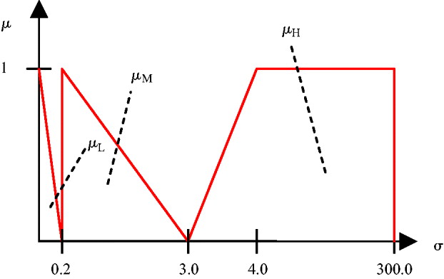
Figure 8. Output membership functions for low medium and high noise characteristics (not to scale).
The equations that describe the membership functions in Figure 8 are as follows:
The inference engine receives the input membership degrees (i.e., μ R(x i), μ w(x i), and μ s(x i)) and examines the fuzzy rules to determine which rules will fire. Membership degrees that are non-zero will fire their respective rules. After determining which rules will fire, it is determined which output membership functions will be applicable.
Defuzzification was carried out using the ‘clipped centre of gravity’ method. The applicable output membership functions, which were determined above, are clipped at their corresponding firing strengths and the centroid of the composite area is calculated. The horizontal coordinate of the centroid is the output of the controller. In discrete form, the horizontal coordinate is determined using Equation (14), below.
The output in this case is σ Ax, the noise on the longitudinal accelerometer, where σ Ax2*T s is used in the process noise covariance matrix. The greatest computational burden in the Fuzzy Logic controller occurs in determining the composite, clipped membership function at each time step which is used in Equation (14).
3.6. Experimental Results
Figures 9–11 illustrate the canine navigation results from an example trial using the Fuzzy Logic with/without an adaptively tuned EKF. Figure 9 is a plot of the canine's position. A simulated GPS outage, where GPS measurements were denied, was used to evaluate the navigation performance during a short GPS outage. The trial length is about 43 seconds, and the simulated GPS outage is initiated 10 seconds before the end of the trial. The GPS position results are considered to be the ‘true’ solution and are plotted with blue dots for the sake of comparison. The position estimate using the adaptive scheme without a GPS outage is shown with a cyan line. The position estimates from standard and adaptive EKF schemes with the GPS outage are plotted in green and red lines, respectively. By the end of the ten second outage, the adaptive position results are within two metres of the GPS solution, while the standard position results yield an error of approximately six and a half metres by the end of the GPS outage. Note that on the eastern and western legs of the trial, the GPS solution is slightly ‘crunched’ together, rather than being spread out similarly to the northern and southern legs. This was primarily due to unfavourable satellite geometry on the day of the trial and could have deleteriously affected the accelerometer bias estimate. However, the adaptive EKF solution was robust enough to maintain an accurate estimate of the position during the GPS outage.
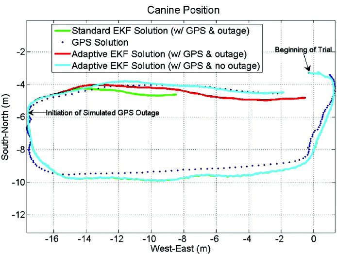
Figure 9. Fuzzy Logic adaptively tuned EKF versus standard EKF and GPS only position estimates. A simulated GPS outage occurs during the last 10 seconds of the trial and is illustrated by the red and green lines.

Figure 10. The differences between the Fuzzy Logic adaptively tuned EKF and GPS position measurements, as well as the difference between the standard EKF and GPS position estimates. A simulated GPS outage occurs during the last 10 seconds of the trial. Commencement of the simulated GPS outage is illustrated by the black line.

Figure 11. Fuzzy Logic adaptively tuned velocity, adaptive and standard EKF accelerometer bias estimates, and Fuzzy Logic adaptively tuned noise characteristics for use in the Q matrix. A simulated GPS outage occurs during the last 10 seconds of the trial, commencing at the blue line.
Figure 10 illustrates the difference between the position solutions using the standard/adaptive EKF schemes and GPS position solution throughout the trial. As discussed above, the approaches deviate more from the GPS position solution between approximately 5 through 26 seconds due to satellite geometry issues. After the GPS outage at approximately 33 seconds, the standard EKF scheme difference begins a steep climb through the rest of the trial, ending at about six and a half metres difference between the EKF solution and the GPS solution. However, the Fuzzy Logic adaptive approach yields position results that are less than two and a half metres in difference throughout the outage, ultimately ending with one and a half metres in difference between the EKF solution and the GPS measurements.
Figure 11 illustrates the canine navigation results for the trial using the adaptive scheme. Accelerometer bias estimate results using the adaptive and standard schemes are shown, as well as the adaptively tuned noise characteristics for use in the Q matrix. Note that at approximately 6.5 seconds, there is a momentary change in velocity which causes a notable divergence in the bias estimations using the two approaches. A study of the heading, accelerometer, and pitch measurements reveals that the canine likely jerked at that moment (which happens frequently), injecting motion behaviour that is not accounted for in the model of the canine that is used by the standard EKF. The Fuzzy Logic EKF adjusted the noise characteristics in the Q matrix accordingly to account for the momentary injection of excess ‘noise’ and continued to move towards the true bias, while the standard EKF bias estimate diverged and climbed for a couple seconds (between the times of 6 and 8 seconds, approximately) in response to the noise before re-commencing the necessary decline towards the desired bias estimate. The standard EKF approach does not recover quickly enough from this large disturbance in acceleration. This results in the standard EKF's estimate of the accelerometer bias (0·07 m/s2), while the adaptive scheme reaches −0·09 m/s2 at the time of the GPS outage, which ultimately results in a superior position solution over the standard approach during the outage, as illustrated in Figure 9.
Table 2 illustrates the average motion tracking results from several trials spread out over three days for the canine using the adaptive, Fuzzy Logic EKF. The trials were each between 40 and 45 seconds. A simulated GPS outage occurs for the last 10 seconds of each trial, thus allowing the EKF at least 30 seconds to estimate the accelerometer bias in each trial. The results from (Miller, Reference Miller2010), where the process noise covariance matrix remained constant throughout each trial, are illustrated as well, for the sake of comparison. The navigation system using the Fuzzy Logic-based adaptive EKF scheme results in a 35% improvement in position error (i.e., the difference between the filtered results and GPS results) after the simulated GPS outage. The adaptive scheme resulted in a 57% improvement in velocity error. These results were found to be statistically significant using the appropriate T-tests.
Table 2. Average canine motion tracking error comparisons using standard and adaptive EKF approaches after a 10 second GPS outage, as well as two-tailed, unpaired t-test results. The canine is in odor detection mode.
n=31 and 36 for constant and adaptive, respectively
Notable is the fact that the standard deviations on the position and velocity results decreased significantly as well, by 21% and 50%, respectively. This indicates that not only is the error smaller on average for the position and velocity results with the adaptive scheme, but that even when higher errors occur in trials, the results will still likely be closer to the average than they would have been using the previous approach. Also notable is the fact that the GPS solution is only known to be accurate to within a circle with a radius of approximately 3·5 metres (based on the horizontal accuracy measurement provided by the GPS receiver). If the GPS solution is off by 3·5 metres in the opposite direction of the EKF solution, it implies that the error in position illustrated in Table 2 (i.e., the difference between the EKF solution and the true solution, rather than the GPS solution) could actually be up to 3·5 meters less than what is exhibited in the chart.
4. CONCLUSIONS
Canines have been shown to be effective candidates for search and rescue, explosives and narcotics detection, and many other scenarios due to their keen sense of smell, size, temperament, and ability to traverse a wide range of terrains with ease. Auburn University has demonstrated that canines can be remotely controlled using tones and vibrations. In order to autonomously control such canines to various endpoints without the need of handlers, an efficient outdoor navigation system had to be developed which would allow for brief Global Positioning System (GPS) outages and be packaged in such a way as to be able to be comfortably carried by the canine while it works. The algorithms presented in this paper present a method to locate a canine's position, velocity, and orientation for use in an outdoor autonomous control system in a computationally inexpensive way; especially without having to investigate the existence of other un-modelled canine motion characteristics beyond those discussed in (Miller, Reference Miller2010) and used in the motion model discussed here. The navigation system discussed in this paper has been shown to be an improvement over the previous autonomously controlled canine navigation algorithms developed by the authors.
It is evident from the results that the use of Fuzzy Logic-based adaptive tuning of the process noise covariance matrix produces improved tracking results for the canine application. The results would likely be even better if the trials were longer. If each trial were longer, the Extended Kalman Filter (EKF) would have more time to hone in on an estimate of the accelerometer bias to a higher degree of accuracy. In a real-world application, a GPS outage would not likely occur during the first minute of the navigation system's initiation. Therefore, longer trials would be a reasonable adjustment. However, in order to be able to compare the current scheme with the schemes presented in (Miller, Reference Miller2010), as well as illustrate the fact that the Fuzzy Logic scheme allows for quicker honing of the accelerometer bias estimate, the trial lengths were kept approximately the same.
Suggested further work would include a more in-depth analysis of canine running motion and subsequent improved tuning of the running and high noise membership functions. It is expected that the adaptive scheme will provide a significant improvement over the standard EKF when analysing canine running motion.
ACKNOWLEDGEMENTS
This work was funded by the Office of Naval Research YIP grant N00014-06-1-0518.


